EP1219475A1 - Apparatus for controlling semi-active suspension system - Google Patents
Apparatus for controlling semi-active suspension system Download PDFInfo
- Publication number
- EP1219475A1 EP1219475A1 EP00128697A EP00128697A EP1219475A1 EP 1219475 A1 EP1219475 A1 EP 1219475A1 EP 00128697 A EP00128697 A EP 00128697A EP 00128697 A EP00128697 A EP 00128697A EP 1219475 A1 EP1219475 A1 EP 1219475A1
- Authority
- EP
- European Patent Office
- Prior art keywords
- roll
- value
- ride
- vehicular
- velocity
- Prior art date
- Legal status (The legal status is an assumption and is not a legal conclusion. Google has not performed a legal analysis and makes no representation as to the accuracy of the status listed.)
- Withdrawn
Links
- 239000000725 suspension Substances 0.000 title claims abstract description 17
- 239000006096 absorbing agent Substances 0.000 claims abstract description 27
- 230000035939 shock Effects 0.000 claims abstract description 27
- 238000013016 damping Methods 0.000 claims abstract description 26
- 230000001133 acceleration Effects 0.000 claims abstract description 24
- 230000006835 compression Effects 0.000 claims abstract description 22
- 238000007906 compression Methods 0.000 claims abstract description 22
- 239000012530 fluid Substances 0.000 claims abstract description 6
- 238000001914 filtration Methods 0.000 claims description 4
- 230000010354 integration Effects 0.000 claims description 3
- 238000000034 method Methods 0.000 description 8
- 238000010586 diagram Methods 0.000 description 4
- 230000004044 response Effects 0.000 description 3
- 238000005096 rolling process Methods 0.000 description 3
- 230000008859 change Effects 0.000 description 1
- 238000006073 displacement reaction Methods 0.000 description 1
- 230000007246 mechanism Effects 0.000 description 1
- 230000004048 modification Effects 0.000 description 1
- 238000012986 modification Methods 0.000 description 1
- 230000008569 process Effects 0.000 description 1
Images


Classifications
-
- B—PERFORMING OPERATIONS; TRANSPORTING
- B60—VEHICLES IN GENERAL
- B60G—VEHICLE SUSPENSION ARRANGEMENTS
- B60G17/00—Resilient suspensions having means for adjusting the spring or vibration-damper characteristics, for regulating the distance between a supporting surface and a sprung part of vehicle or for locking suspension during use to meet varying vehicular or surface conditions, e.g. due to speed or load
- B60G17/015—Resilient suspensions having means for adjusting the spring or vibration-damper characteristics, for regulating the distance between a supporting surface and a sprung part of vehicle or for locking suspension during use to meet varying vehicular or surface conditions, e.g. due to speed or load the regulating means comprising electric or electronic elements
- B60G17/016—Resilient suspensions having means for adjusting the spring or vibration-damper characteristics, for regulating the distance between a supporting surface and a sprung part of vehicle or for locking suspension during use to meet varying vehicular or surface conditions, e.g. due to speed or load the regulating means comprising electric or electronic elements characterised by their responsiveness, when the vehicle is travelling, to specific motion, a specific condition, or driver input
-
- B—PERFORMING OPERATIONS; TRANSPORTING
- B60—VEHICLES IN GENERAL
- B60G—VEHICLE SUSPENSION ARRANGEMENTS
- B60G2400/00—Indexing codes relating to detected, measured or calculated conditions or factors
- B60G2400/10—Acceleration; Deceleration
- B60G2400/102—Acceleration; Deceleration vertical
-
- B—PERFORMING OPERATIONS; TRANSPORTING
- B60—VEHICLES IN GENERAL
- B60G—VEHICLE SUSPENSION ARRANGEMENTS
- B60G2400/00—Indexing codes relating to detected, measured or calculated conditions or factors
- B60G2400/10—Acceleration; Deceleration
- B60G2400/104—Acceleration; Deceleration lateral or transversal with regard to vehicle
-
- B—PERFORMING OPERATIONS; TRANSPORTING
- B60—VEHICLES IN GENERAL
- B60G—VEHICLE SUSPENSION ARRANGEMENTS
- B60G2400/00—Indexing codes relating to detected, measured or calculated conditions or factors
- B60G2400/20—Speed
- B60G2400/204—Vehicle speed
-
- B—PERFORMING OPERATIONS; TRANSPORTING
- B60—VEHICLES IN GENERAL
- B60G—VEHICLE SUSPENSION ARRANGEMENTS
- B60G2400/00—Indexing codes relating to detected, measured or calculated conditions or factors
- B60G2400/20—Speed
- B60G2400/206—Body oscillation speed; Body vibration frequency
-
- B—PERFORMING OPERATIONS; TRANSPORTING
- B60—VEHICLES IN GENERAL
- B60G—VEHICLE SUSPENSION ARRANGEMENTS
- B60G2400/00—Indexing codes relating to detected, measured or calculated conditions or factors
- B60G2400/40—Steering conditions
- B60G2400/41—Steering angle
-
- B—PERFORMING OPERATIONS; TRANSPORTING
- B60—VEHICLES IN GENERAL
- B60G—VEHICLE SUSPENSION ARRANGEMENTS
- B60G2500/00—Indexing codes relating to the regulated action or device
- B60G2500/10—Damping action or damper
-
- B—PERFORMING OPERATIONS; TRANSPORTING
- B60—VEHICLES IN GENERAL
- B60G—VEHICLE SUSPENSION ARRANGEMENTS
- B60G2600/00—Indexing codes relating to particular elements, systems or processes used on suspension systems or suspension control systems
- B60G2600/16—Integrating means, i.e. integral control
-
- B—PERFORMING OPERATIONS; TRANSPORTING
- B60—VEHICLES IN GENERAL
- B60G—VEHICLE SUSPENSION ARRANGEMENTS
- B60G2600/00—Indexing codes relating to particular elements, systems or processes used on suspension systems or suspension control systems
- B60G2600/18—Automatic control means
- B60G2600/184—Semi-Active control means
-
- B—PERFORMING OPERATIONS; TRANSPORTING
- B60—VEHICLES IN GENERAL
- B60G—VEHICLE SUSPENSION ARRANGEMENTS
- B60G2600/00—Indexing codes relating to particular elements, systems or processes used on suspension systems or suspension control systems
- B60G2600/60—Signal noise suppression; Electronic filtering means
- B60G2600/602—Signal noise suppression; Electronic filtering means high pass
-
- B—PERFORMING OPERATIONS; TRANSPORTING
- B60—VEHICLES IN GENERAL
- B60G—VEHICLE SUSPENSION ARRANGEMENTS
- B60G2600/00—Indexing codes relating to particular elements, systems or processes used on suspension systems or suspension control systems
- B60G2600/60—Signal noise suppression; Electronic filtering means
- B60G2600/604—Signal noise suppression; Electronic filtering means low pass
-
- B—PERFORMING OPERATIONS; TRANSPORTING
- B60—VEHICLES IN GENERAL
- B60G—VEHICLE SUSPENSION ARRANGEMENTS
- B60G2800/00—Indexing codes relating to the type of movement or to the condition of the vehicle and to the end result to be achieved by the control action
- B60G2800/01—Attitude or posture control
- B60G2800/012—Rolling condition
-
- B—PERFORMING OPERATIONS; TRANSPORTING
- B60—VEHICLES IN GENERAL
- B60G—VEHICLE SUSPENSION ARRANGEMENTS
- B60G2800/00—Indexing codes relating to the type of movement or to the condition of the vehicle and to the end result to be achieved by the control action
- B60G2800/16—Running
- B60G2800/162—Reducing road induced vibrations
-
- B—PERFORMING OPERATIONS; TRANSPORTING
- B60—VEHICLES IN GENERAL
- B60G—VEHICLE SUSPENSION ARRANGEMENTS
- B60G2800/00—Indexing codes relating to the type of movement or to the condition of the vehicle and to the end result to be achieved by the control action
- B60G2800/24—Steering, cornering
-
- B—PERFORMING OPERATIONS; TRANSPORTING
- B60—VEHICLES IN GENERAL
- B60G—VEHICLE SUSPENSION ARRANGEMENTS
- B60G2800/00—Indexing codes relating to the type of movement or to the condition of the vehicle and to the end result to be achieved by the control action
- B60G2800/90—System Controller type
- B60G2800/91—Suspension Control
- B60G2800/912—Attitude Control; levelling control
-
- B—PERFORMING OPERATIONS; TRANSPORTING
- B60—VEHICLES IN GENERAL
- B60G—VEHICLE SUSPENSION ARRANGEMENTS
- B60G2800/00—Indexing codes relating to the type of movement or to the condition of the vehicle and to the end result to be achieved by the control action
- B60G2800/90—System Controller type
- B60G2800/91—Suspension Control
- B60G2800/916—Body Vibration Control
Definitions
- the present invention relates to an apparatus for controlling a semi-active suspension system; and, more particularly, to an apparatus for controlling a semi-active suspension system using a variable damping force type shock absorber, wherein the damping force characteristics in rebound strokes and in compression strokes are controlled independently by means of separate control valves and utilizing a magnetorheological fluid.
- damping forces of respective shock absorbers are controlled independently by measuring the behavior of respective wheels by using, for example, vertical acceleration sensors installed at respective portions of the vehicle body adjacent to the shock absorbers.
- the so-called "sky-hook” method is usually employed.
- This control method works as follows: when the direction of a vehicular vertical velocity is upward with respect to a road surface, the damping force characteristic in rebound strokes becomes hard, i.e., the damping force becomes relatively large, whereas the damping force characteristic in compression strokes becomes soft, i.e., the damping force becomes relatively small; and when a direction of a vehicular vertical velocity is downward with respect to a road surface, the damping force characteristic in rebound strokes becomes soft or relatively small, while the damping force characteristic in compression strokes becomes hard or relatively large.
- shock absorbers are employed for the semi-active suspension system.
- One is a reverse type semi-active damper and the other a normal type semi-active damper.
- the "sky-hook" control method can be applied by measuring vehicular vertical velocities only.
- the suspension system using reverse type semi-active dampers cannot offer an anti-roll control for preventing rolling behavior which occurs when a vehicle is steering.
- a suspension system using the normal type semi-active dampers can adopt the "sky-hook" control method as well as prevent the rolling behavior.
- vertical velocities of axles as well as vehicular vertical velocities should be measured, requiring more sensors than the suspension system using the reverse type semi-active dampers.
- an object of the present invention to provide an apparatus for controlling a semi-active suspension system using a variable damping force type shock absorber, wherein damping force characteristics in rebound strokes and in compression strokes are controlled independently and MR fluids are utilized.
- an apparatus for controlling a semi-active suspension system of a vehicle including at least one shock absorber using a magnetorheological fluid.
- the shock absorber has a rebound valve and a compression valve which are configured such that damping forces of the shock absorber generated in rebound strokes and compression strokes are controlled independently of each other.
- the apparatus comprises a normal driving control unit for determining a ride value ( S ride ) as well as a filtered vehicular vertical velocity ( ⁇ i ) based on a vehicular vertical acceleration; an anti-roll control unit for determining a roll value ( S roll ) based on a velocity and a steering angle of the vehicle; and a damping force adjusting unit for controlling the rebound valve and the compression valve of the shock absorber based on the roll value ( S roll ), the ride value ( S ride ) and the filtered vehicular vertical velocity ( ⁇ i ) under a predetermined condition.
- Fig. 1 shows a schematic block diagram of an apparatus for controlling a semi-active suspension system in accordance with a preferred embodiment of the present invention.
- the apparatus for controlling a semi-active suspension system comprises a normal driving control unit 10, an anti-roll control unit 20, a damping force adjusting unit 30 and sensors S1-S6.
- the normal driving control unit 10 includes an integrator 11, a ride value calculating part 12 and a filtering part 13, as shown in Fig. 2.
- the integrator 11 is electrically connected to the vertical acceleration sensors S1, S2, S3 and S4 and receives vehicular vertical acceleration signals detected thereby.
- powers of the respective vehicular vertical velocities are determined by calculating absolute values thereof and then filtering the absolute values through a low pass filter which has a cut-off frequency of 0.5 Hz as follows:
- ride value S ride is determined by the ride value calculating part 12 as follows: where K ride_reb , K ride_comp are gains having predetermined values, respectively.
- the anti-roll control part 20 includes a steering rate detecting part 21 and a roll value calculating part 22 and is electrically connected to a steering angle sensor S5 and a vehicle speed sensor S6.
- signals detected by the sensors S5 and S6 are delivered into the steering rate detecting part 21.
- a rolling velocity of a vehicle is proportional to a lateral acceleration of the vehicle and the lateral acceleration can be determined by using a steering angle displacement and a vehicular velocity of the vehicle.
- This operation value S i will be larger than zero when the vertical velocity is upward and smaller than zero when the vertical velocity is downward.
- damping force characteristics are varied continuously and can be controlled independently in rebound strokes and compression strokes, respectively. Further, response times are fast enough to realize the required ride comfort and anti-roll control. Furthermore, an optimal contacting state of a vehicle can be established when the inventive apparatus is used with an anti-lock brake system (ABS) and the like.
- ABS anti-lock brake system
Landscapes
- Engineering & Computer Science (AREA)
- Mechanical Engineering (AREA)
- Vehicle Body Suspensions (AREA)
Abstract
An apparatus for controlling a semi-active suspension
system of a vehicle including at least one shock absorber
using magnetorheological fluids. The shock absorber
has a rebound valve and a compression valve
which are configured such that damping forces of the
shock absorber generated in rebound strokes and compression
strokes being controlled independently. The
apparatus comprises a normal driving control unit for
determining a ride value (Sride ) and a filtered vehicular
vertical velocity (vi ) based on a vertical vehicular
acceleration, an anti-roll control unit for determining
a roll value (Sroll ) based on a velocity and a
steering angle of the vehicle, and a damping force adjusting
unit for controlling the rebound valve and the
compression valve of the shock absorber based on the
roll value (Sroll ), the ride value (Sride ) and the filtered
vehicular vertical velocity (vi ) under a predetermined
condition.
Description
- The present invention relates to an apparatus for controlling a semi-active suspension system; and, more particularly, to an apparatus for controlling a semi-active suspension system using a variable damping force type shock absorber, wherein the damping force characteristics in rebound strokes and in compression strokes are controlled independently by means of separate control valves and utilizing a magnetorheological fluid.
- In a semi-active suspension system for a vehicle, damping forces of respective shock absorbers are controlled independently by measuring the behavior of respective wheels by using, for example, vertical acceleration sensors installed at respective portions of the vehicle body adjacent to the shock absorbers.
- As a control method for such a semi-active suspension system, the so-called "sky-hook" method is usually employed. This control method works as follows: when the direction of a vehicular vertical velocity is upward with respect to a road surface, the damping force characteristic in rebound strokes becomes hard, i.e., the damping force becomes relatively large, whereas the damping force characteristic in compression strokes becomes soft, i.e., the damping force becomes relatively small; and when a direction of a vehicular vertical velocity is downward with respect to a road surface, the damping force characteristic in rebound strokes becomes soft or relatively small, while the damping force characteristic in compression strokes becomes hard or relatively large.
- Conventionally, two types of shock absorbers are employed for the semi-active suspension system. One is a reverse type semi-active damper and the other a normal type semi-active damper. In a suspension system using the reverse type semi-active dampers, the "sky-hook" control method can be applied by measuring vehicular vertical velocities only. However, the suspension system using reverse type semi-active dampers cannot offer an anti-roll control for preventing rolling behavior which occurs when a vehicle is steering. On the other hand, a suspension system using the normal type semi-active dampers can adopt the "sky-hook" control method as well as prevent the rolling behavior. However, in this system, vertical velocities of axles as well as vehicular vertical velocities should be measured, requiring more sensors than the suspension system using the reverse type semi-active dampers.
- In order to solve these problems, an apparatus and a method for controlling damping force characteristic of a vehicular shock absorber and two types of shock absorbers therefor have been disclosed in U.S. Pat. No. 6,092,011. In order to control the damping force characteristics of the shock absorbers, a first type shock absorber uses a control valve driven by a stepping motor while a second type shock absorber uses throttling mechanisms driven by solenoid valves. However, in such a configuration, the damping force characteristics do not change continuously and their response times are not fast enough, which give performance restrictions.
- As a shock absorber which has continuous damping force characteristics and response times fast enough, magnetorheological (MR) fluid dampers have been proposed in U.S. Pat. No. 5,277,281. However, no control method is provided in this patent.
- It is, therefore, an object of the present invention to provide an apparatus for controlling a semi-active suspension system using a variable damping force type shock absorber, wherein damping force characteristics in rebound strokes and in compression strokes are controlled independently and MR fluids are utilized.
- In accordance with a preferred embodiment of the present invention, there is provided an apparatus for controlling a semi-active suspension system of a vehicle including at least one shock absorber using a magnetorheological fluid. The shock absorber has a rebound valve and a compression valve which are configured such that damping forces of the shock absorber generated in rebound strokes and compression strokes are controlled independently of each other. The apparatus comprises a normal driving control unit for determining a ride value (Sride ) as well as a filtered vehicular vertical velocity (νi ) based on a vehicular vertical acceleration; an anti-roll control unit for determining a roll value (Sroll ) based on a velocity and a steering angle of the vehicle; and a damping force adjusting unit for controlling the rebound valve and the compression valve of the shock absorber based on the roll value (Sroll ), the ride value (Sride ) and the filtered vehicular vertical velocity (νi) under a predetermined condition.
- The above and other objects and features of the present invention will become apparent from the following description of preferred embodiments given in conjunction with the accompanying drawings, in which:
- Fig. 1
- shows a schematic block diagram of an apparatus for controlling a semi-active suspension system in accordance with a preferred embodiment of the present invention;
- Fig. 2
- illustrates a block diagram of the normal driving control unit shown in Fig. 1; and
- Fig. 3
- describes a block diagram of the anti-roll control unit shown in Fig. 1.
- Preferred embodiments of the present invention will now be described in detail with reference to the accompanying drawings.
- Fig. 1 shows a schematic block diagram of an apparatus for controlling a semi-active suspension system in accordance with a preferred embodiment of the present invention. As shown in Fig. 1, the apparatus for controlling a semi-active suspension system comprises a normal
driving control unit 10, ananti-roll control unit 20, a dampingforce adjusting unit 30 and sensors S1-S6. - The normal
driving control unit 10 includes anintegrator 11, a ridevalue calculating part 12 and a filteringpart 13, as shown in Fig. 2. - The
integrator 11 is electrically connected to the vertical acceleration sensors S1, S2, S3 and S4 and receives vehicular vertical acceleration signals detected thereby. Vehicular vertical velocities νh are derived by performing integration in either z-domain or s-domain as follows: - During this process, low frequency components of the vehicular vertical acceleration signals are removed therefrom.
- Next, powers of the respective vehicular vertical velocities are determined by calculating absolute values thereof and then filtering the absolute values through a low pass filter which has a cut-off frequency of 0.5 Hz as follows:
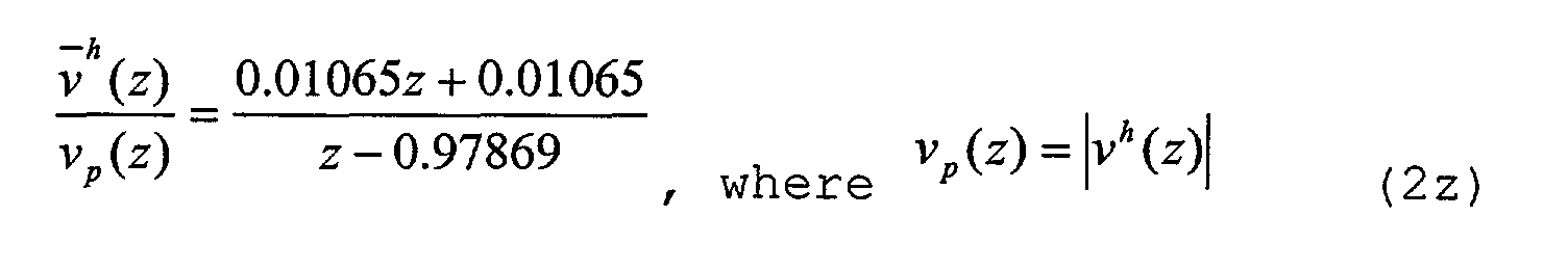

- Further, the vehicular vertical acceleration signals are filtered through a band pass filter and filtered vehicular vertical velocities are determined by the filtering
part 13 as follows:
 where Kν is a tuning variable, νi a filtered vertical velocity and the
superscript 10 Hz bandwidth of a band pass filter. - When the frequency of the vertical acceleration is high, the vehicular vertical velocity νh becomes relatively large and, when the frequency of the vertical acceleration is low, the vehicular vertical velocity νh becomes relatively small.
- Then, ride value Sride is determined by the ride
value calculating part 12 as follows: where Kride_reb, Kride_comp are gains having predetermined values, respectively.
- As shown in Fig. 3, the
anti-roll control part 20 includes a steeringrate detecting part 21 and a rollvalue calculating part 22 and is electrically connected to a steering angle sensor S5 and a vehicle speed sensor S6. - First, signals detected by the sensors S5 and S6 are delivered into the steering
rate detecting part 21. - A rolling velocity of a vehicle is proportional to a lateral acceleration of the vehicle and the lateral acceleration can be determined by using a steering angle displacement and a vehicular velocity of the vehicle. The lateral acceleration of the vehicle is determined as follows:
- Then, a time delay is taken into consideration for the lateral acceleration determined above as follows:
- The roll
value calculating part 22 calculates a roll value based on the lateral acceleration determined above as follows: - Typically, Kroll is a function of a slip ratio □ and defined as follows:
- The damping
force adjusting unit 30 receives the ride value Sride and the roll value Sroll and determines an operation value Si . More specifically, when the roll value Sroll is larger than 70, operation values Si for front and rear shock absorbers are determined as follows: - On the other hand, when the roll value is smaller than or equal to 70, the operation value Si is determined as follows:
- This operation value Si will be larger than zero when the vertical velocity is upward and smaller than zero when the vertical velocity is downward. In order to realize the "sky-hook" control, the operation values for the front and rear shock absorber are determined as follows:
- Finally, current amounts for the respective MR dampers are determined as follows:
- When the operation values SiR or SiC are greater than 128, the currents are set as follows:
- These currents are delivered to the rebound valve and the compression valve of MR dampers and damping force characteristics of each MR damper are controlled independently.
- In the apparatus in accordance with the present invention, damping force characteristics are varied continuously and can be controlled independently in rebound strokes and compression strokes, respectively. Further, response times are fast enough to realize the required ride comfort and anti-roll control. Furthermore, an optimal contacting state of a vehicle can be established when the inventive apparatus is used with an anti-lock brake system (ABS) and the like.
- Although the invention has been shown and described with respect to the preferred embodiments, it will be understood by those skilled in the art that various changes and modifications may be made without departing from the scope of the invention as defined in the following claims.
Claims (18)
- An apparatus for controlling a semi-active suspension system of a vehicle including at least one shock absorber using magnetorheological fluids, the shock absorber having a rebound valve and a compression valve which are configured such that damping forces of the shock absorber generated in rebound strokes and compression strokes are controlled independently of each other, the apparatus comprising:a normal driving control unit for determining a ride value (Sride ) and a filtered vehicular vertical velocity (νi ) based on a vehicular vertical acceleration;an anti-roll control unit for determining a roll value (Sroll ) based on a velocity and a steering angle of the vehicle; anda damping force adjusting unit for controlling the rebound valve and the compression valve of the shock absorber based on the roll value (Sroll ), the ride value (Sride ) and the filtered vehicular vertical velocity (νi ) under a predetermined condition.
- The apparatus of claim 1, wherein the normal driving control unit includes an integrator for determining a vehicular vertical velocity (νh ) by integrating the vehicular vertical acceleration (a) detected by an acceleration sensor, a filtering part for determining the filtered vertical velocity (νi ) based on the vehicular vertical acceleration (a) and the vehicular vertical velocity (νh ) and a ride value calculating part for calculating the ride value (Sride ) based on the vehicular vertical velocity (νh ) and the filtered vertical velocity (νi ).
- The apparatus of claim 2, wherein the integration operation of the integrator is performed such that the following equation holds:a(z) is the vertical vehicular acceleration, andνh (z) is the vehicular vertical velocity.
- The apparatus of claims 2 or 3, wherein the filtered vertical velocity (νi ) is determined such that the following equation holds:
 wherein
Kν is a gain having a predetermined value. - The apparatus any one of claims 2 to 4, wherein the ride value (Sride ) is calculated such that the following equation holds:
 wherein
Kride_reb, Kride_comp are gains having predetermined values, and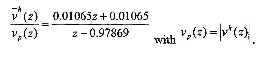
- The apparatus of claim 2, wherein the integration operation of the integrator is performed such that the following equation holds:a(s) is the vertical acceleration, andνh (s) is the vehicular vertical velocity.
- The apparatus of claims 2 or 6, wherein the filtered vertical velocity (νi ) is determined such that the following equation holds:
 wherein
Kν is a gain having a predetermined value. - The apparatus any one of claims 2, 6 and 7,
wherein the ride value (Sride ) is calculated such that the following equation holds: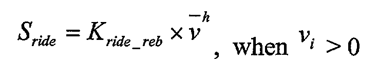 wherein

- The apparatus of claim 1, wherein the anti-roll control part includes a steering rate detecting part for determining a lateral acceleration (ay ) based on a velocity and a steering angle of the vehicle and a roll value calculating part for determining the roll value (Sroll ) based on the lateral acceleration (ay ).
- The apparatus of claim 9, wherein the lateral acceleration (ay ) is determined such that the following equation holds:is is a steering gear ratio,δ ˙sw is a steering wheel angle ratio,l is a length of wheel base,V is a vehicular velocity, andVch is a characteristic velocity.
- The apparatus of claims 9 or 10, wherein the roll value (Sroll ) is calculated such that the following equation holds:
- The apparatus of claims 9 or 10, wherein the roll value (Sroll ) is calculated such that the following equation holds:
- The apparatus of claim 1, wherein, when the roll value (Sroll ) is larger than a predetermined value, an amount of control current for the rebound valve (AR ) and that for the compression valve (AC ) of the shock absorber are determined such that the following equation holds:
- The apparatus of claim 13, wherein, when SiR is greater than 128, the amounts of control current for the rebound valve (AR ) has a value of 3.
- The apparatus of claim 13, wherein, when SiC is greater than 128, the amounts of control current for the compression valve (AC ) has a value of 3.
- The apparatus of claim 1, wherein, when the roll value (Sroll ) is smaller than a predetermined value, an amount of control currents for the rebound valve (AR ) and that for the compression valve (AC ) of the shock absorber are determined by the damping force adjusting unit such that the following equation holds:
- The apparatus of claim 16, wherein, when SiR is greater than 128, the amounts of control current for the rebound valve (AR ) has a value of 3.
- The apparatus of claim 16, wherein, when SiC is greater than 128, the amounts of control current for the compression valve (AC ) has a value of 3.
Priority Applications (1)
| Application Number | Priority Date | Filing Date | Title |
|---|---|---|---|
| EP00128697A EP1219475A1 (en) | 2000-12-29 | 2000-12-29 | Apparatus for controlling semi-active suspension system |
Applications Claiming Priority (1)
| Application Number | Priority Date | Filing Date | Title |
|---|---|---|---|
| EP00128697A EP1219475A1 (en) | 2000-12-29 | 2000-12-29 | Apparatus for controlling semi-active suspension system |
Publications (1)
| Publication Number | Publication Date |
|---|---|
| EP1219475A1 true EP1219475A1 (en) | 2002-07-03 |
Family
ID=8170862
Family Applications (1)
| Application Number | Title | Priority Date | Filing Date |
|---|---|---|---|
| EP00128697A Withdrawn EP1219475A1 (en) | 2000-12-29 | 2000-12-29 | Apparatus for controlling semi-active suspension system |
Country Status (1)
| Country | Link |
|---|---|
| EP (1) | EP1219475A1 (en) |
Cited By (21)
| Publication number | Priority date | Publication date | Assignee | Title |
|---|---|---|---|---|
| EP1391330A3 (en) * | 2002-08-20 | 2005-04-06 | Mando Corporation | An anti-roll or anti-yaw suspension device for vehicles |
| CN103303087A (en) * | 2013-06-25 | 2013-09-18 | 吉林大学 | Control system for semi-active suspension frame of magnetorheological damper |
| US9205717B2 (en) | 2012-11-07 | 2015-12-08 | Polaris Industries Inc. | Vehicle having suspension with continuous damping control |
| US9662954B2 (en) | 2012-11-07 | 2017-05-30 | Polaris Industries Inc. | Vehicle having suspension with continuous damping control |
| CN107215165A (en) * | 2017-06-08 | 2017-09-29 | 南京林业大学 | Automobile active tilting control method based on big damping force magneto-rheological semiactive suspension |
| US10124709B2 (en) | 2015-05-15 | 2018-11-13 | Polaris Industries Inc. | Utility vehicle |
| US10406884B2 (en) | 2017-06-09 | 2019-09-10 | Polaris Industries Inc. | Adjustable vehicle suspension system |
| CN110712490A (en) * | 2018-07-13 | 2020-01-21 | 山东大学 | An active suspension system based on stack self-encoding and its working method |
| US10946736B2 (en) | 2018-06-05 | 2021-03-16 | Polaris Industries Inc. | All-terrain vehicle |
| US10987987B2 (en) | 2018-11-21 | 2021-04-27 | Polaris Industries Inc. | Vehicle having adjustable compression and rebound damping |
| US11110913B2 (en) | 2016-11-18 | 2021-09-07 | Polaris Industries Inc. | Vehicle having adjustable suspension |
| US11285964B2 (en) | 2014-10-31 | 2022-03-29 | Polaris Industries Inc. | System and method for controlling a vehicle |
| US11904648B2 (en) | 2020-07-17 | 2024-02-20 | Polaris Industries Inc. | Adjustable suspensions and vehicle operation for off-road recreational vehicles |
| US12172518B2 (en) | 2019-04-30 | 2024-12-24 | Polaris Industries Inc. | Vehicle |
| US12187127B2 (en) | 2020-05-15 | 2025-01-07 | Polaris Industries Inc. | Off-road vehicle |
| US12384464B2 (en) | 2020-05-15 | 2025-08-12 | Polaris Industries Inc. | Off-road vehicle |
| US12385429B2 (en) | 2022-06-13 | 2025-08-12 | Polaris Industries Inc. | Powertrain for a utility vehicle |
| US12391116B2 (en) | 2010-06-03 | 2025-08-19 | Polaris Industries Inc. | Adjustable performance for a vehicle |
| US12397878B2 (en) | 2020-05-20 | 2025-08-26 | Polaris Industries Inc. | Systems and methods of adjustable suspensions for off-road recreational vehicles |
| USD1103845S1 (en) | 2023-01-20 | 2025-12-02 | Polaris Industries Inc. | Grille for an off-road vehicle |
| USD1120805S1 (en) | 2023-06-29 | 2026-03-31 | Polaris Industries Inc. | Body assembly for an off-road vehicle |
Citations (9)
| Publication number | Priority date | Publication date | Assignee | Title |
|---|---|---|---|---|
| US4970645A (en) * | 1987-04-09 | 1990-11-13 | Hitachi, Ltd. | Suspension control method and apparatus for vehicle |
| US5193845A (en) * | 1990-07-31 | 1993-03-16 | Nissan Motor Co., Ltd. | Vehicle vibration damping force control system |
| US5277281A (en) | 1992-06-18 | 1994-01-11 | Lord Corporation | Magnetorheological fluid dampers |
| US5360089A (en) * | 1992-05-21 | 1994-11-01 | Unisia Jecs Corporation | Automotive suspension control system utilizing variable damping force shock absorber |
| GB2279425A (en) * | 1991-01-31 | 1995-01-04 | Fichtel & Sachs Ag | Controlling a vibration damper |
| US5398184A (en) * | 1991-11-01 | 1995-03-14 | Atsugi Unisia Corp. | Apparatus for controlling damping coefficient of vehicular shock absorber |
| WO1999007567A1 (en) * | 1997-08-05 | 1999-02-18 | Unisia Jecs Corporation | Suspension systems for motor vehicles |
| US5987369A (en) * | 1996-10-31 | 1999-11-16 | Mando Machinery Corporation | System and method of controlling semiactive suspension |
| US6092011A (en) | 1997-04-08 | 2000-07-18 | Unisia Jecs Corporation | Apparatus and method for controlling damping force characteristic of vehicular shock absorber |
-
2000
- 2000-12-29 EP EP00128697A patent/EP1219475A1/en not_active Withdrawn
Patent Citations (9)
| Publication number | Priority date | Publication date | Assignee | Title |
|---|---|---|---|---|
| US4970645A (en) * | 1987-04-09 | 1990-11-13 | Hitachi, Ltd. | Suspension control method and apparatus for vehicle |
| US5193845A (en) * | 1990-07-31 | 1993-03-16 | Nissan Motor Co., Ltd. | Vehicle vibration damping force control system |
| GB2279425A (en) * | 1991-01-31 | 1995-01-04 | Fichtel & Sachs Ag | Controlling a vibration damper |
| US5398184A (en) * | 1991-11-01 | 1995-03-14 | Atsugi Unisia Corp. | Apparatus for controlling damping coefficient of vehicular shock absorber |
| US5360089A (en) * | 1992-05-21 | 1994-11-01 | Unisia Jecs Corporation | Automotive suspension control system utilizing variable damping force shock absorber |
| US5277281A (en) | 1992-06-18 | 1994-01-11 | Lord Corporation | Magnetorheological fluid dampers |
| US5987369A (en) * | 1996-10-31 | 1999-11-16 | Mando Machinery Corporation | System and method of controlling semiactive suspension |
| US6092011A (en) | 1997-04-08 | 2000-07-18 | Unisia Jecs Corporation | Apparatus and method for controlling damping force characteristic of vehicular shock absorber |
| WO1999007567A1 (en) * | 1997-08-05 | 1999-02-18 | Unisia Jecs Corporation | Suspension systems for motor vehicles |
Cited By (46)
| Publication number | Priority date | Publication date | Assignee | Title |
|---|---|---|---|---|
| CN1298557C (en) * | 2002-08-20 | 2007-02-07 | 株式会社万都 | Method for anti-side listing /anti-cross oscillating controlling vehicles |
| EP1391330A3 (en) * | 2002-08-20 | 2005-04-06 | Mando Corporation | An anti-roll or anti-yaw suspension device for vehicles |
| US12391116B2 (en) | 2010-06-03 | 2025-08-19 | Polaris Industries Inc. | Adjustable performance for a vehicle |
| US12291069B2 (en) | 2012-11-07 | 2025-05-06 | Polaris Industries Inc. | Vehicle having suspension with continuous damping control |
| US11400784B2 (en) | 2012-11-07 | 2022-08-02 | Polaris Industries Inc. | Vehicle having suspension with continuous damping control |
| US9205717B2 (en) | 2012-11-07 | 2015-12-08 | Polaris Industries Inc. | Vehicle having suspension with continuous damping control |
| US11124036B2 (en) | 2012-11-07 | 2021-09-21 | Polaris Industries Inc. | Vehicle having suspension with continuous damping control |
| US10005335B2 (en) | 2012-11-07 | 2018-06-26 | Polaris Industries Inc. | Vehicle having suspension with continuous damping control |
| US11400785B2 (en) | 2012-11-07 | 2022-08-02 | Polaris Industries Inc. | Vehicle having suspension with continuous damping control |
| US11970036B2 (en) | 2012-11-07 | 2024-04-30 | Polaris Industries Inc. | Vehicle having suspension with continuous damping control |
| US11400787B2 (en) | 2012-11-07 | 2022-08-02 | Polaris Industries Inc. | Vehicle having suspension with continuous damping control |
| US9662954B2 (en) | 2012-11-07 | 2017-05-30 | Polaris Industries Inc. | Vehicle having suspension with continuous damping control |
| US11400786B2 (en) | 2012-11-07 | 2022-08-02 | Polaris Industries Inc. | Vehicle having suspension with continuous damping control |
| CN103303087A (en) * | 2013-06-25 | 2013-09-18 | 吉林大学 | Control system for semi-active suspension frame of magnetorheological damper |
| US11919524B2 (en) | 2014-10-31 | 2024-03-05 | Polaris Industries Inc. | System and method for controlling a vehicle |
| US12325432B2 (en) | 2014-10-31 | 2025-06-10 | Polaris Industries Inc. | System and method for controlling a vehicle |
| US11285964B2 (en) | 2014-10-31 | 2022-03-29 | Polaris Industries Inc. | System and method for controlling a vehicle |
| US11752860B2 (en) | 2015-05-15 | 2023-09-12 | Polaris Industries Inc. | Utility vehicle |
| US12552246B2 (en) | 2015-05-15 | 2026-02-17 | Polaris Industries Inc. | Utility vehicle |
| US10124709B2 (en) | 2015-05-15 | 2018-11-13 | Polaris Industries Inc. | Utility vehicle |
| US11110913B2 (en) | 2016-11-18 | 2021-09-07 | Polaris Industries Inc. | Vehicle having adjustable suspension |
| US12337824B2 (en) | 2016-11-18 | 2025-06-24 | Polaris Industries Inc. | Vehicle having adjustable suspension |
| US11878678B2 (en) | 2016-11-18 | 2024-01-23 | Polaris Industries Inc. | Vehicle having adjustable suspension |
| CN107215165B (en) * | 2017-06-08 | 2018-05-11 | 南京林业大学 | Automobile active tilting control method based on big damping force magneto-rheological semiactive suspension |
| CN107215165A (en) * | 2017-06-08 | 2017-09-29 | 南京林业大学 | Automobile active tilting control method based on big damping force magneto-rheological semiactive suspension |
| US11479075B2 (en) | 2017-06-09 | 2022-10-25 | Polaris Industries Inc. | Adjustable vehicle suspension system |
| US11912096B2 (en) | 2017-06-09 | 2024-02-27 | Polaris Industries Inc. | Adjustable vehicle suspension system |
| US10406884B2 (en) | 2017-06-09 | 2019-09-10 | Polaris Industries Inc. | Adjustable vehicle suspension system |
| US12330467B2 (en) | 2017-06-09 | 2025-06-17 | Polaris Industries Inc. | Adjustable vehicle suspension system |
| US10987989B2 (en) | 2017-06-09 | 2021-04-27 | Polaris Industries Inc. | Adjustable vehicle suspension system |
| US10946736B2 (en) | 2018-06-05 | 2021-03-16 | Polaris Industries Inc. | All-terrain vehicle |
| CN110712490A (en) * | 2018-07-13 | 2020-01-21 | 山东大学 | An active suspension system based on stack self-encoding and its working method |
| US12384214B2 (en) | 2018-11-21 | 2025-08-12 | Polaris Industries Inc. | Vehicle having adjustable compression and rebound damping |
| US11975584B2 (en) | 2018-11-21 | 2024-05-07 | Polaris Industries Inc. | Vehicle having adjustable compression and rebound damping |
| US10987987B2 (en) | 2018-11-21 | 2021-04-27 | Polaris Industries Inc. | Vehicle having adjustable compression and rebound damping |
| US11884117B2 (en) | 2018-11-21 | 2024-01-30 | Polaris Industries Inc. | Vehicle having adjustable compression and rebound damping |
| US12172518B2 (en) | 2019-04-30 | 2024-12-24 | Polaris Industries Inc. | Vehicle |
| US12337690B2 (en) | 2020-05-15 | 2025-06-24 | Polaris Industries Inc. | Off-road vehicle |
| US12384464B2 (en) | 2020-05-15 | 2025-08-12 | Polaris Industries Inc. | Off-road vehicle |
| US12187127B2 (en) | 2020-05-15 | 2025-01-07 | Polaris Industries Inc. | Off-road vehicle |
| US12397878B2 (en) | 2020-05-20 | 2025-08-26 | Polaris Industries Inc. | Systems and methods of adjustable suspensions for off-road recreational vehicles |
| US11904648B2 (en) | 2020-07-17 | 2024-02-20 | Polaris Industries Inc. | Adjustable suspensions and vehicle operation for off-road recreational vehicles |
| US12552215B2 (en) | 2020-07-17 | 2026-02-17 | Polaris Industries Inc. | Adjustable suspensions and vehicle operation for off-road recreational vehicles |
| US12385429B2 (en) | 2022-06-13 | 2025-08-12 | Polaris Industries Inc. | Powertrain for a utility vehicle |
| USD1103845S1 (en) | 2023-01-20 | 2025-12-02 | Polaris Industries Inc. | Grille for an off-road vehicle |
| USD1120805S1 (en) | 2023-06-29 | 2026-03-31 | Polaris Industries Inc. | Body assembly for an off-road vehicle |
Similar Documents
| Publication | Publication Date | Title |
|---|---|---|
| US6507778B2 (en) | Apparatus for controlling semi-active suspension system | |
| EP1219475A1 (en) | Apparatus for controlling semi-active suspension system | |
| US5638275A (en) | Apparatus and method for controlling damping force characteristic of vehicular shock absorber | |
| EP0492782B1 (en) | Automotive apparatus and method for dynamically determining the centripetal force of a vehicle | |
| US5377107A (en) | System and method for controlling damping force characteristic of shock absorber applicable to automotive suspension | |
| EP0556055B1 (en) | Suspension system for a motor vehicle | |
| JP2917652B2 (en) | Suspension control device | |
| EP2022655B1 (en) | Control apparatus of a variable damping force damper | |
| US6202011B1 (en) | Electronic controlled suspension system using wheel speed | |
| US7715963B2 (en) | Stabilizer control apparatus | |
| KR19980031243A (en) | Semi-active Electronic Control Suspension and Method of Vehicle | |
| US20080009992A1 (en) | Control device of variable damping force damper | |
| EP0752330A2 (en) | Automotive vehicle suspension control system | |
| EP1104357B1 (en) | Vehicle suspensions | |
| US8855856B2 (en) | Vehicle roll control method using controllable friction force of MR dampers | |
| GB2391327A (en) | A system for sensing vehicle attitudes | |
| JPH04504701A (en) | Control device for suspension control of land vehicles | |
| US5852787A (en) | Vehicle suspension control | |
| JP2002219921A (en) | Control device for semiactive suspension system | |
| EP1659008B1 (en) | Method for the regulation or control of the damping force of an adjustable vehicle damper | |
| EP0963867A1 (en) | Vehicle suspension control system and method | |
| JP3158734B2 (en) | Contact load estimation device, longitudinal acceleration calculation device and lateral acceleration calculation device | |
| CN111347830A (en) | Suspension control system for vehicle | |
| US5706196A (en) | Method and apparatus for determining the velocity of a vehicle body | |
| JPH11268512A (en) | Vehicle damping coefficient control device |
Legal Events
| Date | Code | Title | Description |
|---|---|---|---|
| PUAI | Public reference made under article 153(3) epc to a published international application that has entered the european phase |
Free format text: ORIGINAL CODE: 0009012 |
|
| AK | Designated contracting states |
Kind code of ref document: A1 Designated state(s): AT BE CH CY DE DK ES FI FR GB GR IE IT LI LU MC NL PT SE TR |
|
| AX | Request for extension of the european patent |
Free format text: AL;LT;LV;MK;RO;SI |
|
| 17P | Request for examination filed |
Effective date: 20021218 |
|
| AKX | Designation fees paid |
Designated state(s): DE FR GB IT |
|
| 17Q | First examination report despatched |
Effective date: 20040622 |
|
| STAA | Information on the status of an ep patent application or granted ep patent |
Free format text: STATUS: THE APPLICATION IS DEEMED TO BE WITHDRAWN |
|
| 18D | Application deemed to be withdrawn |
Effective date: 20041103 |