EP1219474A1 - Strut mount - Google Patents
Strut mount Download PDFInfo
- Publication number
- EP1219474A1 EP1219474A1 EP01932094A EP01932094A EP1219474A1 EP 1219474 A1 EP1219474 A1 EP 1219474A1 EP 01932094 A EP01932094 A EP 01932094A EP 01932094 A EP01932094 A EP 01932094A EP 1219474 A1 EP1219474 A1 EP 1219474A1
- Authority
- EP
- European Patent Office
- Prior art keywords
- nut
- attachment
- attachment piece
- vehicle body
- strut mount
- Prior art date
- Legal status (The legal status is an assumption and is not a legal conclusion. Google has not performed a legal analysis and makes no representation as to the accuracy of the status listed.)
- Granted
Links
Images


Classifications
-
- F—MECHANICAL ENGINEERING; LIGHTING; HEATING; WEAPONS; BLASTING
- F16—ENGINEERING ELEMENTS AND UNITS; GENERAL MEASURES FOR PRODUCING AND MAINTAINING EFFECTIVE FUNCTIONING OF MACHINES OR INSTALLATIONS; THERMAL INSULATION IN GENERAL
- F16B—DEVICES FOR FASTENING OR SECURING CONSTRUCTIONAL ELEMENTS OR MACHINE PARTS TOGETHER, e.g. NAILS, BOLTS, CIRCLIPS, CLAMPS, CLIPS OR WEDGES; JOINTS OR JOINTING
- F16B37/00—Nuts or like thread-engaging members
- F16B37/04—Devices for fastening nuts to surfaces, e.g. sheets, plates
- F16B37/06—Devices for fastening nuts to surfaces, e.g. sheets, plates by means of welding or riveting
- F16B37/062—Devices for fastening nuts to surfaces, e.g. sheets, plates by means of welding or riveting by means of riveting
- F16B37/065—Devices for fastening nuts to surfaces, e.g. sheets, plates by means of welding or riveting by means of riveting by deforming the material of the nut
-
- B—PERFORMING OPERATIONS; TRANSPORTING
- B60—VEHICLES IN GENERAL
- B60G—VEHICLE SUSPENSION ARRANGEMENTS
- B60G13/00—Resilient suspensions characterised by arrangement, location or type of vibration dampers
- B60G13/001—Arrangements for attachment of dampers
- B60G13/003—Arrangements for attachment of dampers characterised by the mounting on the vehicle body or chassis of the damper unit
-
- B—PERFORMING OPERATIONS; TRANSPORTING
- B60—VEHICLES IN GENERAL
- B60G—VEHICLE SUSPENSION ARRANGEMENTS
- B60G15/00—Resilient suspensions characterised by arrangement, location or type of combined spring and vibration damper, e.g. telescopic type
- B60G15/02—Resilient suspensions characterised by arrangement, location or type of combined spring and vibration damper, e.g. telescopic type having mechanical spring
- B60G15/06—Resilient suspensions characterised by arrangement, location or type of combined spring and vibration damper, e.g. telescopic type having mechanical spring and fluid damper
- B60G15/067—Resilient suspensions characterised by arrangement, location or type of combined spring and vibration damper, e.g. telescopic type having mechanical spring and fluid damper characterised by the mounting on the vehicle body or chassis of the spring and damper unit
-
- F—MECHANICAL ENGINEERING; LIGHTING; HEATING; WEAPONS; BLASTING
- F16—ENGINEERING ELEMENTS AND UNITS; GENERAL MEASURES FOR PRODUCING AND MAINTAINING EFFECTIVE FUNCTIONING OF MACHINES OR INSTALLATIONS; THERMAL INSULATION IN GENERAL
- F16F—SPRINGS; SHOCK-ABSORBERS; MEANS FOR DAMPING VIBRATION
- F16F9/00—Springs, vibration-dampers, shock-absorbers, or similarly-constructed movement-dampers using a fluid or the equivalent as damping medium
- F16F9/32—Details
- F16F9/54—Arrangements for attachment
-
- B—PERFORMING OPERATIONS; TRANSPORTING
- B60—VEHICLES IN GENERAL
- B60G—VEHICLE SUSPENSION ARRANGEMENTS
- B60G2200/00—Indexing codes relating to suspension types
- B60G2200/40—Indexing codes relating to the wheels in the suspensions
- B60G2200/46—Indexing codes relating to the wheels in the suspensions camber angle
-
- B—PERFORMING OPERATIONS; TRANSPORTING
- B60—VEHICLES IN GENERAL
- B60G—VEHICLE SUSPENSION ARRANGEMENTS
- B60G2202/00—Indexing codes relating to the type of spring, damper or actuator
- B60G2202/30—Spring/Damper and/or actuator Units
- B60G2202/31—Spring/Damper and/or actuator Units with the spring arranged around the damper, e.g. MacPherson strut
- B60G2202/312—The spring being a wound spring
-
- B—PERFORMING OPERATIONS; TRANSPORTING
- B60—VEHICLES IN GENERAL
- B60G—VEHICLE SUSPENSION ARRANGEMENTS
- B60G2204/00—Indexing codes related to suspensions per se or to auxiliary parts
- B60G2204/10—Mounting of suspension elements
- B60G2204/12—Mounting of springs or dampers
- B60G2204/124—Mounting of coil springs
-
- B—PERFORMING OPERATIONS; TRANSPORTING
- B60—VEHICLES IN GENERAL
- B60G—VEHICLE SUSPENSION ARRANGEMENTS
- B60G2204/00—Indexing codes related to suspensions per se or to auxiliary parts
- B60G2204/10—Mounting of suspension elements
- B60G2204/12—Mounting of springs or dampers
- B60G2204/124—Mounting of coil springs
- B60G2204/1242—Mounting of coil springs on a damper, e.g. MacPerson strut
-
- B—PERFORMING OPERATIONS; TRANSPORTING
- B60—VEHICLES IN GENERAL
- B60G—VEHICLE SUSPENSION ARRANGEMENTS
- B60G2204/00—Indexing codes related to suspensions per se or to auxiliary parts
- B60G2204/10—Mounting of suspension elements
- B60G2204/12—Mounting of springs or dampers
- B60G2204/128—Damper mount on vehicle body or chassis
-
- B—PERFORMING OPERATIONS; TRANSPORTING
- B60—VEHICLES IN GENERAL
- B60G—VEHICLE SUSPENSION ARRANGEMENTS
- B60G2204/00—Indexing codes related to suspensions per se or to auxiliary parts
- B60G2204/40—Auxiliary suspension parts; Adjustment of suspensions
- B60G2204/41—Elastic mounts, e.g. bushings
-
- B—PERFORMING OPERATIONS; TRANSPORTING
- B60—VEHICLES IN GENERAL
- B60G—VEHICLE SUSPENSION ARRANGEMENTS
- B60G2204/00—Indexing codes related to suspensions per se or to auxiliary parts
- B60G2204/40—Auxiliary suspension parts; Adjustment of suspensions
- B60G2204/416—Ball or spherical joints
-
- B—PERFORMING OPERATIONS; TRANSPORTING
- B60—VEHICLES IN GENERAL
- B60G—VEHICLE SUSPENSION ARRANGEMENTS
- B60G2204/00—Indexing codes related to suspensions per se or to auxiliary parts
- B60G2204/40—Auxiliary suspension parts; Adjustment of suspensions
- B60G2204/43—Fittings, brackets or knuckles
-
- B—PERFORMING OPERATIONS; TRANSPORTING
- B60—VEHICLES IN GENERAL
- B60G—VEHICLE SUSPENSION ARRANGEMENTS
- B60G2204/00—Indexing codes related to suspensions per se or to auxiliary parts
- B60G2204/40—Auxiliary suspension parts; Adjustment of suspensions
- B60G2204/44—Centering or positioning means
-
- B—PERFORMING OPERATIONS; TRANSPORTING
- B60—VEHICLES IN GENERAL
- B60G—VEHICLE SUSPENSION ARRANGEMENTS
- B60G2204/00—Indexing codes related to suspensions per se or to auxiliary parts
- B60G2204/40—Auxiliary suspension parts; Adjustment of suspensions
- B60G2204/44—Centering or positioning means
- B60G2204/4404—Retainers for holding a fixing element, e.g. bushing, nut, bolt etc., until it is tightly fixed in position
-
- B—PERFORMING OPERATIONS; TRANSPORTING
- B60—VEHICLES IN GENERAL
- B60G—VEHICLE SUSPENSION ARRANGEMENTS
- B60G2204/00—Indexing codes related to suspensions per se or to auxiliary parts
- B60G2204/40—Auxiliary suspension parts; Adjustment of suspensions
- B60G2204/45—Stops limiting travel
- B60G2204/4502—Stops limiting travel using resilient buffer
- B60G2204/45021—Stops limiting travel using resilient buffer for limiting upper mount movement of a McPherson strut
-
- B—PERFORMING OPERATIONS; TRANSPORTING
- B60—VEHICLES IN GENERAL
- B60G—VEHICLE SUSPENSION ARRANGEMENTS
- B60G2204/00—Indexing codes related to suspensions per se or to auxiliary parts
- B60G2204/61—Adjustable during maintenance
-
- B—PERFORMING OPERATIONS; TRANSPORTING
- B60—VEHICLES IN GENERAL
- B60G—VEHICLE SUSPENSION ARRANGEMENTS
- B60G2206/00—Indexing codes related to the manufacturing of suspensions: constructional features, the materials used, procedures or tools
- B60G2206/01—Constructional features of suspension elements, e.g. arms, dampers, springs
- B60G2206/80—Manufacturing procedures
- B60G2206/82—Joining
- B60G2206/8207—Joining by screwing
Definitions
- This invention relates to a strut mount disposed at an attachment portion of a buffer to a vehicle.
- a so-called strut mount is disposed at an attachment portion of a buffer to a vehicle body, in order to control vibration, etc. propagated from wheels to the vehicle body.
- Fig. 12 shows an example of a conventional strut mount.
- the strut mount 100 comprises an inner fitting 101 in which the upper extremity of a piston rod 110 of a shock absorber is inserted, an outer fitting 102 attached to the vehicle body side, and a rubber elastomer 103 interposed between both fittings to dampen input vibration.
- the rod 110 inserted into the inner fitting 101 is fixed to the inner fitting 101 when being fastened by a nut 104.
- the outer fitting 102 is provided with an attachment piece 105, to which a bolt 107 inserted into a bolt hole 106 thereof from below is press fitted and secured.
- the strut mount 100 With the bolt 107 lifted up so as to insert into a bolt hole 113 of the vehicle body's attachment plate 112 from below, by tightening a nut 108 from above the attachment plate 112 of the vehicle body, the strut mount 100 will be attached to the vehicle body only by attachment working from above.
- an object of the present invention is to provide the improvement of vehicle running stability by raising the rigidity of the attachment structure of a strut mount to a vehicle.
- the form of a sphere denotes a curved surface forming a part of a sphere.
- the attachment piece of the outer member is curved in the form of a sphere
- the surface fastening to the vehicle body is also in the form of a sphere. Accordingly, when a rubber elastomer is formed, it poses a problem that a rubber burr is liable to be produced when a rubber comes into the fastening surface. Since a bolt cannot be tightened by a predetermined torque due to the presence of the rubber burr and deteriorated rubber may cause the tightened bolt to be loosened, it is necessary to get rid of the rubber burr after forming, leading to a cause of higher working cost.
- the present invention provides a strut mount according to a second embodiment that the elastomer is a rubber elastomer stuck to the inner and outer members by means of die forming, the outer member being equipped with an attachment piece fitted and secured to an attachment plate of a vehicle from underneath, the attachment piece being equipped with a fastening surface portion that is exposed from the rubber elastomer and tightened to the attachment plate of the vehicle by the bolts, and non-fastening surface portion being provided so as to be lowered via a different level portion around the fastening surface portion.
- the elastomer is a rubber elastomer stuck to the inner and outer members by means of die forming
- the outer member being equipped with an attachment piece fitted and secured to an attachment plate of a vehicle from underneath
- the attachment piece being equipped with a fastening surface portion that is exposed from the rubber elastomer and tightened to the attachment plate of the vehicle by the bolts, and non-fastening surface portion being provided so as to be lowered via a different level
- the rubber when forming the rubber elastomer, the rubber is prevented from coming into the fastening surface portion by pressing the forcing surface portion provided on the forming die against the non-fastening surface portion. That is, according to the second embodiment, since the non-fastening surface portion is provided so as to be lowered via a different level portion around the fastening surface portion of the attachment piece, the non-fastening surface portion can serve as a sealing surface portion to prevent the rubber in a cavity of the forming die from getting into the fastening surface, thus preventing the rubber burr from producing on the fastening surface.
- the second embodiment is to prevent the rubber from coming into the fastening surface portion by pressing the forcing surface portion of the forming die against the non-fastening surface portion.
- the forcing surface portion is pressed against the non-fastening surface, any effect is not produced on fastening to the attachment plate of the vehicle body even if any surface becomes rough due to forcing or urging.
- a sealing protrusion can be provided on the forcing surface portion of the forming die and pressed against the non-fastening surface portion, thus capable of preventing the rubber more effectively from coming into the fastening surface.
- the non-fastening surface portion can be configured in the form of a plane as against the spherical fastening surface portion, it is easy for the forming die to press the non-fastening surface portion.
- each bolt 203 fitted and secured to the attachment piece 202 is disposed toward individual inclined direction as against the direction of movement (perpendicularly) when the strut mount is lifted up.
- the present invention is to provide a strut mount according to a third embodiment by providing a nut under the attachment piece of an outer member, screwing a bolt into the nut from above the attachment plate of the vehicle body, inserting the bolt without making the bolt hole larger, and tightening the attachment piece of the outer member to the underneath of the attachment plate of the vehicle body with a bolt.
- the third embodiment adopts a nut caulked and secured on the lower surface side of the attachment piece.
- a means for caulking and securing the nut is to form a nut attachment hole on the attachment piece of the outer member and to insert the caulking nut having a cylindrical portion from underneath the attachment piece.
- the cylindrical portion is caulked and upset, an outer circumferential surface of the cylindrical portion is stuck fast to an inner circumferential surface of the nut attachment hole, thus capable of sticking the nut on the lower surface side of the attachment piece.
- an extra wall surrounding the nut attachment hole cuts into the corrugated outer circumferential surface of the cylindrical portion as the nut attachment hole is diminished in diameter, the extra wall acts as a steady rest to restrain the caulking nut from turning together with the bolt.
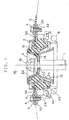
- the strut mount 10 according to the first embodiment of the present invention is explained on the basis of Figs. 1 to 5.
- the strut mount 10 comprises an inner fitting 12 which is fixed by inserting an upper extremity la of a piston rod 1 of a shock absorber from below, an outer fitting 14 attached to the vehicle body side, surrounding an outer circumference of the inner fitting 12, and a rubber elastomer 16 in the form of a ring interposed between the inner and outer fittings 12, 14 to unite both in one piece, and is attached to an attachment plate 2 of the vehicle body, curved in the form of upwardly convex sphere.
- the attachment plate 2 of the vehicle body has an opening 3, to which the strut mount 10 is assembled from below.
- the inner fitting 12 is a roughly tubular steel product disposed on the inside of the rubber elastomer 16, and at its outer circumferential surface an inner circumferential surface of the rubber elastomer 16 is vulcanization bonded.
- the inner fitting 12 has a circular fixed surface portion 18 square to the rod 1, an opening 20 is provided at the center of the fixed surface portion 18, and the rod 1 is fixed to the fixed surface portion 18 by a nut 9 under a condition of being inserted into the opening 20.
- the inner fitting 12 comprises a first member 22 in the form of a cup having upward opening with the fixed surface portion 18 as a bottom surface, a second member 24 in the form of a cup having downward opening to receive the upper extremity of the rod 1 from below, and the fixed surface portion 18 is formed by jointing both bottom surfaces of the first and second members 22, 24.
- the second member 24 serves as a seat for a bound bumper.
- the outer fitting 14 is a steel product comprised of a cylindrical portion 26 disposed nearly parallel to the inner fitting 12 so as to cover the inner fitting 12 from outside and an attachment piece 28 extendedly disposed outwardly in the direction square to the axial direction from the upper extremity of the cylindrical portion 26, and embedded in the rubber elastomer 16.
- the attachment piece 28 is curved in the form of a sphere of upwardly convex in corresponding with a shape of the lower surface of the attachment plate 28.
- the attachment piece 28 is provided with a fastening surface portion 30 exposed from the rubber elastomer 16 and fastened to the attachment plate 2 of the vehicle body by the bolt.
- the fastening surface portion 30 is provided at three points at a circumferential edge of the outer fitting 14 as shown in Fig. 2.
- a nut 32 screwed by the bolt 4 inserted from the upper side of the attachment plate 2 of the vehicle body is provided integrally on the fastening surface portion 30 by burring working.
- a non-fastening surface portion 36 lowered via a different level portion 34 is provided so as to surround the fastening surface portion 30.
- the fastening surface portion 36 is formed in the form of a plane with respect to the spherical fastening surface portion 30, lower than the fastening surface portion 30 by one step. Therefore, the non-fastening surface portion 36 is disposed oppositely via a slight clearance under a condition where the attachment piece 28 is fixed to the attachment plate 2 of the vehicle body, with non-contacting condition with the underneath of the attachment plate 2.
- the rubber elastomer 16 is vulcanization formed with the first member 22 of the inner fitting 12 and the outer fitting 14 set up in a die 40.
- the fastening surface portion 30 of the attachment piece 28 is in the state of being exposed from the rubber elastomer 16 when being interposed between an upper die 42 and a lower die 44.
- a forcing surface portion 46 forcing the non-fastening surface portion 36 is provided for the upper die 42 disposed on the upper surface side of the attachment piece 28.
- the forcing surface portion 46 is provided so as to be pressed against the non-fastening surface portion 36 around the fastening surface portion 30, instead of the fastening surface portion 30, when closing the dies.
- the rubber is thus prevented from coming into the fastening surface portion 30 outside of the non-fastening surface portion 36 by pressing the forcing surface portion 46 against the non-fastening surface portion 36.
- curving the attachment piece 28 of the outer fitting 14 and the attachment plate 2 of the vehicle body in the form of a sphere allows the attachment portion of the strut mount 10 to have high rigidity, bringing about good running properties.
- Fig. 5 shows an example of modified forcing surface portion 46 in the aforementioned embodiment.
- a sealing protrusion 48 with a sectional shape of roughly triangle is provided, extending along the different level portion 34, for the forcing surface portion 46, and pressed against and cut into the non-fastening surface portion 36.
- the sectional shape of the sealing protrusion 48 is not limited to a triangle, and semi-circular and rectangular shape may also be used.
- the second embodiment differs from the first embodiment in that a caulking nut 52 is provided, instead of the aforementioned nut 32 produced by the burring working, as a nut screwed by the bolt 4 that serves to fasten the outer fitting 14 to the vehicle body. Explanation of the points, to which the same number as the first embodiment is designated, is omitted because of the same structure.
- a nut attachment hole 54 is provided, to which a caulking nut 52 is stuck.
- the caulking nut 52 comprises a nut portion 56 disposed on the underside of the attachment piece 28 and a cylindrical portion 58 inserted into the nut attachment hole 54 from the underside.
- screw threads are cut continuously, wherein the bolt 4 is screwed.
- the caulking nut 52 is stuck to the nut attachment hole 54, the circumference of which, on the attachment piece 28, is pressurized and caulked, which is then diminished in diameter.
- the caulking nut 52 is a hardened steel product.
- the nut portion 56 gets caught in the circumferential edge of the nut attachment hole 54 so as not to slip through and come out of the attachment piece 28 upwardly.
- a groove 60 is made around the cylindrical portion 58 on the upper surface of the nut portion 56, so that the extra wall of the attachment piece 28 cuts into there when pressurizing the circumference of the nut attachment hole 54.
- the cylindrical portion 58 has an outside diameter enough to be inserted into the nut attachment hole 54, and its outer circumferential surface is corrugated 62 so that the extra wall of the attachment piece 28 cuts into the cylindrical portion 58 when pressurizing the circumference of the nut attachment hole 54.
- the extra wall being cut into serves to restrain the caulking nut 52 from slipping through downward.
- the procedure of attaching the strut mount 50 to the attachment plate 2 of a vehicle body is described below.
- the cylindrical portion 58 of the caulking nut 52 is inserted from below into the nut attachment hole 54 of the strut mount 50 being assembled, and then the circumference of the nut attachment hole 54 of the attachment piece 28 is pressurized and caulked from above.
- the nut attachment hole 54 is diminished in diameter, and the inner circumferential surface thereof is stuck fast to the cylindrical portion 58.
- the extra wall of the attachment piece 28 cuts into the corrugation 62 on the outer circumferential surface of the cylindrical portion 58, whereby forming a steady rest that restrains the bolt 4 from turning together with the caulking nut 52, with the result to secure a predetermined turning torque. Being made of hardened steel, the caulking nut 52 will not be deformed.
- the bolt 4 can be inserted perpendicularly to the plate surface even when the attachment plate 2 of the vehicle body is curved, it is not necessary to make the bolt hole 5 of the attachment plate 2 larger, and problems such as looseness can be dissolved.
- the attachment piece 28 is caulked to secure the caulking nut 52, it is not necessary to thicken the attachment piece 28 of the outer fitting 14 just like in the case of burring working, so that the weight of the components can be reduced.
- the nut is not welded, post working can easily be performed even after vulcanization forming of the rubber, capable of laborsaving during operations and reducing cost.
- Figs. 9 and 10 show examples of modified caulking nuts. This example relates to the caulking nut 70 the cylindrical portion of which is upset.
- the caulking nut 70 comprises a nut portion 72 disposed on the underside of the attachment piece 28 and a cylindrical portion 74 that is inserted into the nut attachment hole 54 from the underside.
- the caulking nut 70 is caulked, upset and secured to the nut attachment hole 54 by pressurizing and upsetting the cylindrical portion 74 outwardly.
- the caulking nut 70 is a hardened steel product.
- the nut portion 72 gets caught in the circumferential edge of the nut attachment hole 54 so as not to slip through and come out of the attachment piece 28 upwardly.
- screw threads are cut, wherein the bolt 4 is screwed.
- the cylindrical portion 74 has an outside diameter enough to insert into the nut attachment hole 54, and its inside diameter is larger than the I.D. of the nut portion 72 so as not to deform the screw threads of the nut portion 72 when being caulked. Having a chamfering 76 on the above side of the circumferential edge of the nut attachment hole 54, the upsetting upper extremity of the cylindrical portion 74 is gotten caught so as not to slip through and come out of the caulking nut 70 downwardly.
- rigidity can be raised without thickening the attachment plate of a vehicle body to improve vehicle running stability, by curving the attachment piece of the outer member and the attachment plate of the vehicle body in the form of a sphere.
- the non-fastening surface portion is provided by being lowered via a different level portion around the fastening surface portion of the attachment piece of the outer member to the vehicle body, the rubber in a cavity of the forming die is prevented from getting into the fastening surface, thus keeping the rubber burr from being produced on the fastening surface.
- the attachment plate can be curved by the use of the caulking nut stuck to the underside of the attachment piece of the outer member, without enlarging the bolt hole of the attachment plate of the vehicle body, the weight of the products can also be reduced by thinning the plate thickness, and cost reduction can be accomplished by laborsaving during operations.
Landscapes
- Engineering & Computer Science (AREA)
- Mechanical Engineering (AREA)
- General Engineering & Computer Science (AREA)
- Vehicle Body Suspensions (AREA)
- Fluid-Damping Devices (AREA)
- Springs (AREA)
- Vibration Prevention Devices (AREA)
Abstract
Description
Claims (13)
- A strut mount comprising an inner member to which an upper extremity of a rod of a buffer is fixed, an outer member attached to a vehicle body while surrounding an outer circumference of the inner member, and a rubber elastomer interposed between the inner and outer members to dampen vibration:wherein the outer member is provided with an attachment piece that is fitted and secured to an attachment plate of the vehicle body from underneath, and the attachment piece is curved in the form of a sphere corresponding to the shape of the lower surface of the attachment plate curved in the form of a sphere.
- The strut mount as set forth in claim 1, wherein the elastomer is a rubber elastomer stuck to the inner and outer members by means of die forming:wherein the attachment piece of the outer member is equipped with a fastening surface portion that is exposed from the rubber elastomer and tightened to the attachment plate of the vehicle by bolts, and a non-fastening surface portion of plane form is provided around the fastening surface portion by being lowered via a different level portion.
- The strut mount as set forth in claim 1, wherein both the attachment piece of the outer member and the attachment plate of the vehicle body are fastened by tightening a bolt screwed to a nut, which is caulked and secured on the lower surface side of the attachment piece of the outer member, from above the attachment plate of the vehicle body.
- The strut mount as set forth in claim 3, wherein the nut is a caulking nut with a cylindrical portion that is inserted into the nut attachment hole formed on the attachment piece of the outer member, the caulking nut with the upsetting cylindrical portion being stuck to the attachment piece.
- The strut mount as set forth in claim 3, wherein the nut is a caulking nut with the cylindrical portion that is inserted into the nut attachment hole formed on the attachment piece of the outer member, the caulking nut being stuck to the attachment piece by pressurizing the circumference of the nut attachment hole from the direction square to the attachment piece plate surface and diminishing the nut attachment hole in diameter.
- The strut mount as set forth in claim 5, wherein the outer circumferential surface of the cylindrical portion of the caulking nut is corrugated, and an extra wall surrounding the nut attachment hole cuts into the corrugated outer circumferential surface of the cylindrical portion as the nut attachment hole is diminished in diameter, the extra wall acting as a steady rest to restrain the caulking nut from turning together with the bolt.
- A strut mount comprising an inner member to which an upper extremity of a rod of a buffer is fixed, an outer member attached to a vehicle body while surrounding an outer circumference of the inner member, and a rubber elastomer interposed between the inner and outer members to dampen vibration:wherein the elastomer is a rubber elastomer stuck to the inner and outer members by means of die forming:the outer member is provided with the attachment piece that is fitted and secured to an attachment plate of the vehicle body from underneath,the attachment piece is equipped with a fastening surface portion that is exposed from the rubber elastomer and tightened to the attachment plate of the vehicle body by the bolts, and a non-fastening surface portion is provided around the fastening surface portion by being lowered via a different level portion.
- A producing method of the strut mount as set forth in claim 7, wherein, when forming the rubber elastomer, the rubber is prevented from coming into the fastening surface portion by pressing the forcing surface portion provided on the forming die against the non-fastening surface portion.
- The producing method of the strut mount as set forth in claim 8, wherein a sealing protrusion is provided on the forcing surface portion and pressed against the non-fastening surface portion
- The strut mount comprising an inner member to which an upper extremity of a rod of a buffer is fixed, an outer member attached to a vehicle body while surrounding an outer circumference of the inner member, and a rubber elastomer interposed between the inner and outer members to dampen vibration:wherein the outer member is provided with an attachment piece that is fitted and secured to an attachment plate of the vehicle body from underneath, both the attachment piece of the outer member and the attachment plate of the vehicle body are fastened by tightening the bolt screwed to the nut, which is caulked and secured on the lower surface side of the attachment piece, from above the attachment plate of the vehicle body.
- The strut mount as set forth in claim 10, wherein the nut is a caulking nut with a cylindrical portion that is inserted into the nut attachment hole formed on the attachment piece of the outer member, the caulking nut with the upsetting cylindrical portion being stuck to the attachment piece.
- The strut mount as set forth in claim 10, wherein the nut is a caulking nut with the cylindrical portion that is inserted into the nut attachment hole formed on the attachment piece of the outer member, the caulking nut being stuck to the attachment piece by pressurizing the circumference of the nut attachment hole from the direction square to the attachment piece plate surface and diminishing the nut attachment hole in diameter.
- The strut mount as set forth in claim 12, wherein the outer circumferential surface of the cylindrical portion of the caulking nut is corrugated, and an extra wall surrounding the nut attachment hole cuts into the corrugated outer circumferential surface of the cylindrical portion as the nut attachment hole is diminished in diameter, the extra wall acting as a steady rest to restrain the caulking nut from turning together with the bolt.
Applications Claiming Priority (3)
| Application Number | Priority Date | Filing Date | Title |
|---|---|---|---|
| JP2000310055 | 2000-10-11 | ||
| JP2000310055 | 2000-10-11 | ||
| PCT/JP2001/004091 WO2002030694A1 (en) | 2000-10-11 | 2001-05-16 | Strut mount |
Publications (3)
| Publication Number | Publication Date |
|---|---|
| EP1219474A1 true EP1219474A1 (en) | 2002-07-03 |
| EP1219474A4 EP1219474A4 (en) | 2006-11-22 |
| EP1219474B1 EP1219474B1 (en) | 2008-09-10 |
Family
ID=18790076
Family Applications (1)
| Application Number | Title | Priority Date | Filing Date |
|---|---|---|---|
| EP01932094A Expired - Lifetime EP1219474B1 (en) | 2000-10-11 | 2001-05-16 | Strut mount |
Country Status (5)
| Country | Link |
|---|---|
| US (2) | US6969053B2 (en) |
| EP (1) | EP1219474B1 (en) |
| JP (1) | JP3669362B2 (en) |
| DE (1) | DE60135725D1 (en) |
| WO (2) | WO2002030694A1 (en) |
Cited By (2)
| Publication number | Priority date | Publication date | Assignee | Title |
|---|---|---|---|---|
| US6969053B2 (en) * | 2000-10-11 | 2005-11-29 | Toyo Tire & Rubber Co., Ltd. | Strut mount |
| EP1681180A1 (en) * | 2005-01-12 | 2006-07-19 | TOYO TIRE & RUBBER CO., LTD . | Strut mount |
Families Citing this family (34)
| Publication number | Priority date | Publication date | Assignee | Title |
|---|---|---|---|---|
| US20040080086A1 (en) * | 2002-10-23 | 2004-04-29 | Mansueto Mark J. | Resilient bushing mount for a vehicle suspension |
| FR2849139B1 (en) * | 2002-12-23 | 2006-03-03 | Renault Sa | DEVICE FOR HIGHLY ATTACHING A SUSPENSION DAMPER OF A FRONT WHEEL OF A MOTOR VEHICLE |
| KR100527710B1 (en) * | 2003-05-21 | 2005-11-09 | 현대자동차주식회사 | upper mounting structure of rear strut assembly |
| FR2863329B1 (en) * | 2003-12-09 | 2007-08-17 | Hutchinson | SUSPENSION SUPPORT DEVICE AND VEHICLE COMPRISING SUCH A DEVICE |
| DE102004017866A1 (en) * | 2004-04-13 | 2005-11-03 | Profil-Verbindungstechnik Gmbh & Co. Kg | Process for the production of hollow body elements, hollow body element, assembly component and follow-on composite tool for carrying out the method |
| DE102005024220A1 (en) * | 2005-05-25 | 2006-11-30 | Profil Verbindungstechnik Gmbh & Co. Kg | Method for producing hollow body elements, hollow body element, assembly component, progressive composite tool for producing hollow body elements and rolling mill |
| JP2007196982A (en) * | 2005-12-26 | 2007-08-09 | Bridgestone Corp | Strut mount |
| US9169889B1 (en) * | 2006-02-13 | 2015-10-27 | Fox Factory, Inc. | Fluid pressure operated device with adjustable positioning of mounting elements relative to externally mounted structures |
| US7740436B2 (en) * | 2006-03-22 | 2010-06-22 | R B & W Manufacturing Llc | Clinch nut |
| US20070257522A1 (en) * | 2006-05-05 | 2007-11-08 | Textron Inc. | Threaded inserts in struts |
| US8572915B2 (en) * | 2007-11-07 | 2013-11-05 | Gregory L. Meahl | Cove base corner cover |
| US7866102B2 (en) * | 2007-11-07 | 2011-01-11 | Meahl Gregory L | Cove base corner cover |
| JP4923302B2 (en) * | 2008-04-23 | 2012-04-25 | 倉敷化工株式会社 | Upper mount |
| KR101001266B1 (en) * | 2008-11-13 | 2010-12-14 | 주식회사 만도 | Bracket for mounting a shock absorber |
| DE102009042336A1 (en) * | 2009-09-21 | 2011-03-24 | Profil Verbindungstechnik Gmbh & Co. Kg | Self-piercing hollow press-fit, assembly part consisting of a press-in element and a sheet metal part and a method for producing a self-piercing press-in nut and for attaching a self-piercing press-in nut |
| JP5189139B2 (en) * | 2010-06-30 | 2013-04-24 | ピアス販売株式会社 | Clinch bolt |
| JP5876224B2 (en) | 2010-09-28 | 2016-03-02 | 住友理工株式会社 | Upper support manufacturing method |
| DE102011009012A1 (en) * | 2011-01-20 | 2012-07-26 | Profil Verbindungstechnik Gmbh & Co. Kg | Functional element in the form of a press-in element |
| DE102011080505B4 (en) * | 2011-08-05 | 2024-03-28 | Arnold Umformtechnik Gmbh & Co. Kg | fastener |
| EP2799737B1 (en) * | 2011-12-26 | 2017-09-13 | Honda Motor Co., Ltd. | Suspension support structure |
| JP5520990B2 (en) * | 2012-03-22 | 2014-06-11 | 東海ゴム工業株式会社 | Upper support for vehicle suspension |
| EP2644911A3 (en) | 2012-03-27 | 2016-08-17 | Profil Verbindungstechnik GmbH & Co. KG | Function element in the form of a press element |
| JP6160228B2 (en) * | 2013-05-16 | 2017-07-12 | 新日鐵住金株式会社 | Strut mount, strut and suspension device |
| US9539872B2 (en) * | 2014-12-30 | 2017-01-10 | Sungwoo Hitech Co., Ltd. | Mounting unit of shock absorber for vehicle |
| KR101646443B1 (en) * | 2015-01-30 | 2016-08-05 | 현대자동차주식회사 | Polymer Composite Strut Insulator and Suspension System thereby |
| DE102016204619B4 (en) * | 2016-03-21 | 2019-10-17 | Richard Bergner Verbindungstechnik Gmbh & Co. Kg | Press-in connection between a high-strength component and a press-in element, method for forming such a press-in connection and press-in element for such a press-in connection |
| US11358428B2 (en) * | 2017-10-10 | 2022-06-14 | Bridgestone Corporation | Active damper upper mount |
| KR102063682B1 (en) * | 2018-03-15 | 2020-01-09 | 주식회사 일진 | Top mount assembly and method of manufacturing same |
| CN108953349A (en) * | 2018-08-01 | 2018-12-07 | 嘉兴新亚汽车零部件有限公司 | A kind of anti-skidding anchor rivet bush |
| US11209040B2 (en) * | 2019-07-15 | 2021-12-28 | Rb&W Manufacturing Llc | Self-clinching fastener |
| US11459035B1 (en) * | 2021-03-16 | 2022-10-04 | Ford Global Technologies, Llc | Shock absorber assembly structures |
| US11913488B2 (en) | 2021-05-27 | 2024-02-27 | Rb&W Manufacturing Llc | Self-clinching and self-piercing construction element with multi-purpose pilot |
| US12163548B2 (en) | 2022-08-26 | 2024-12-10 | Rb&W Manufacturing Llc | Self-clinching fastener |
| US12611907B1 (en) | 2024-10-30 | 2026-04-28 | Car Sound Exhaust System, Inc. | Vehicle lift spacer apparatus |
Family Cites Families (40)
| Publication number | Priority date | Publication date | Assignee | Title |
|---|---|---|---|---|
| US1705463A (en) * | 1927-07-15 | 1929-03-12 | Smith Corp A O | Attaching tapped nuts to metal plates |
| US1759339A (en) * | 1927-07-15 | 1930-05-20 | Smith Corp A O | Threaded nut for securing metal parts |
| US2138409A (en) * | 1937-07-02 | 1938-11-29 | Lamson & Sessions Co | Clinch nut |
| US2649884A (en) * | 1948-06-17 | 1953-08-25 | Miles R Westover | Attachment nut |
| US2722259A (en) * | 1950-11-01 | 1955-11-01 | Dana C Eckenbeck | Insert nut with ball shaped plate engaging extension |
| GB1197896A (en) * | 1966-08-01 | 1970-07-08 | Silentbloc | Improvements relating to Suspension Units |
| US3736969A (en) * | 1966-09-22 | 1973-06-05 | H Warn | Pierce nut |
| US3845860A (en) * | 1971-04-01 | 1974-11-05 | Multifastener Corp | Fastener strip |
| US3878598A (en) * | 1972-03-27 | 1975-04-22 | Multifastener Corp | Method of forming a nut and panel assembly |
| US3809139A (en) * | 1972-05-26 | 1974-05-07 | Kean Mfg Corp | Clinch-slide nut, panel assembly and method of forming same |
| US4425065A (en) * | 1978-08-24 | 1984-01-10 | Theodore Sweeney & Company | Adhesively securable fastener |
| US4432681A (en) * | 1981-05-28 | 1984-02-21 | Russell Burdsall & Ward Corporation | Fastener |
| JPS60161606A (en) | 1984-02-01 | 1985-08-23 | Matsushita Electric Ind Co Ltd | How to manufacture printed coils |
| JPS60161606U (en) * | 1984-04-05 | 1985-10-26 | トヨタ自動車株式会社 | suspension support |
| JPS60252814A (en) * | 1984-05-29 | 1985-12-13 | 株式会社 青山製作所 | Clinch nut |
| JPS6236804Y2 (en) * | 1984-10-11 | 1987-09-19 | ||
| EP0187970A1 (en) * | 1984-12-14 | 1986-07-23 | FIAT AUTO S.p.A. | Perfected vehicle steering wheel suspension |
| JPH0636344B2 (en) | 1985-03-08 | 1994-05-11 | 株式会社日立製作所 | Liquid metal ion generation method and apparatus |
| JPS61206143U (en) * | 1985-06-14 | 1986-12-26 | ||
| JPS6241435A (en) | 1985-08-19 | 1987-02-23 | Kinugawa Rubber Ind Co Ltd | Strut mount insulator |
| JPH0826916B2 (en) | 1985-09-06 | 1996-03-21 | カヤバ工業株式会社 | Mounting structure of hydraulic shock absorber |
| JPS6336804A (en) | 1986-07-28 | 1988-02-17 | Mitsubishi Rayon Co Ltd | porous membrane |
| DE8802370U1 (en) * | 1988-02-24 | 1988-05-26 | Fichtel & Sachs Ag, 8720 Schweinfurt | Suspension strut for a steered wheel of a vehicle |
| JPH0225049A (en) | 1988-07-14 | 1990-01-26 | Toshiba Corp | Method and apparatus for evaluating semiconductor substrate |
| JPH02117450U (en) | 1989-03-09 | 1990-09-20 | ||
| JPH0747976B2 (en) | 1989-04-14 | 1995-05-24 | 東海ゴム工業株式会社 | Upper support for suspension |
| JPH0749098Y2 (en) | 1989-07-25 | 1995-11-13 | 東海ゴム工業株式会社 | Upper support for suspension |
| JPH0724674Y2 (en) | 1989-08-24 | 1995-06-05 | 東海ゴム工業株式会社 | Upper support for suspension |
| JPH04121557A (en) | 1990-09-10 | 1992-04-22 | Daikin Ind Ltd | Refrigeration machine for extremely low temperature |
| JPH04121557U (en) * | 1991-04-20 | 1992-10-30 | トキコ株式会社 | suspension device |
| JPH073245B2 (en) * | 1991-08-26 | 1995-01-18 | コンドーセイコー株式会社 | Nut and mounting method |
| US5263694A (en) * | 1992-02-24 | 1993-11-23 | General Motors Corporation | Upper mount assembly for a suspension damper |
| JPH073245A (en) | 1993-06-21 | 1995-01-06 | Hitachi Chem Co Ltd | Method for manufacturing expanded graphite composite gasket material |
| US5467971A (en) * | 1994-08-08 | 1995-11-21 | General Motors Corporation | Strut assembly with integral bearing and spring seat |
| JP3533411B2 (en) | 1996-07-01 | 2004-05-31 | 東洋ゴム工業株式会社 | Strut mount insulator |
| JP2000027925A (en) | 1998-07-15 | 2000-01-25 | Toyo Tire & Rubber Co Ltd | Strut mount |
| JP3945036B2 (en) | 1998-09-02 | 2007-07-18 | スズキ株式会社 | Suspension device for automobile |
| FR2783203B1 (en) * | 1998-09-14 | 2001-05-04 | Peugeot | UPPER SUPPORT DEVICE OF A FRONT SUSPENSION SHOCK ABSORBER OF A MOTOR VEHICLE |
| US6220804B1 (en) * | 1999-03-24 | 2001-04-24 | R B & W Corporation | Self-piercing clinch nut |
| DE60135725D1 (en) * | 2000-10-11 | 2008-10-23 | Toyo Tire & Rubber Co | STRUT BEARING MOUNT |
-
2001
- 2001-05-16 DE DE60135725T patent/DE60135725D1/en not_active Expired - Lifetime
- 2001-05-16 EP EP01932094A patent/EP1219474B1/en not_active Expired - Lifetime
- 2001-05-16 US US10/030,778 patent/US6969053B2/en not_active Expired - Lifetime
- 2001-05-16 JP JP2002522482A patent/JP3669362B2/en not_active Expired - Lifetime
- 2001-05-16 WO PCT/JP2001/004091 patent/WO2002030694A1/en not_active Ceased
- 2001-07-26 WO PCT/JP2001/006473 patent/WO2002032701A1/en not_active Ceased
- 2001-07-26 US US10/129,706 patent/US6712370B2/en not_active Expired - Lifetime
Cited By (3)
| Publication number | Priority date | Publication date | Assignee | Title |
|---|---|---|---|---|
| US6969053B2 (en) * | 2000-10-11 | 2005-11-29 | Toyo Tire & Rubber Co., Ltd. | Strut mount |
| EP1681180A1 (en) * | 2005-01-12 | 2006-07-19 | TOYO TIRE & RUBBER CO., LTD . | Strut mount |
| US7350779B2 (en) | 2005-01-12 | 2008-04-01 | Toyo Tire & Rubber Co., Ltd. | Strut mount |
Also Published As
| Publication number | Publication date |
|---|---|
| JPWO2002030694A1 (en) | 2004-02-19 |
| US20030189278A1 (en) | 2003-10-09 |
| EP1219474A4 (en) | 2006-11-22 |
| US6712370B2 (en) | 2004-03-30 |
| US6969053B2 (en) | 2005-11-29 |
| JP3669362B2 (en) | 2005-07-06 |
| US20020163155A1 (en) | 2002-11-07 |
| WO2002030694A1 (en) | 2002-04-18 |
| EP1219474B1 (en) | 2008-09-10 |
| DE60135725D1 (en) | 2008-10-23 |
| WO2002032701A1 (en) | 2002-04-25 |
Similar Documents
| Publication | Publication Date | Title |
|---|---|---|
| US6969053B2 (en) | Strut mount | |
| EP0922866B1 (en) | Fastener and panel assembly and method of making same | |
| US6543979B2 (en) | Clinch nut assembly and method of producing clinch nut | |
| JP3781057B2 (en) | Rivetable element, assembly, assembly method and riveting die | |
| US5584628A (en) | Device for connecting parts having holes with different center-to-center distances | |
| US6640942B2 (en) | Suspension support | |
| US6918277B2 (en) | Method of working end part of metallic tube body and metallic tube body, and method of manufacturing vibrationproof bush using the working method and vibrationproof bush | |
| JP4777454B2 (en) | Fastening method of subframe to automobile body with fastening bolt | |
| US7350779B2 (en) | Strut mount | |
| US6616160B2 (en) | Strut mount | |
| CN102022413A (en) | Press-in element, assembly including same and method of manufacturing and attaching press-in cap | |
| US7341243B2 (en) | Liquid-sealed vibration control device | |
| US20210001677A1 (en) | A spring assembly for a vehicle bogie suspension arrangement | |
| JP2008291874A (en) | Flat washer crimp bolt and its manufacturing method | |
| US7232117B2 (en) | Pneumatic spring pot and method for producing same | |
| US20160375939A1 (en) | Vehicle and a cradle assembly for the vehicle | |
| US6688823B2 (en) | Fastening position adjustable bolt and mount construction of members using the same | |
| EP1511942B1 (en) | One-piece flag nut | |
| US20080166200A1 (en) | Device for establishing desired minimum preload condition obtained in a fastener shank | |
| CN215751771U (en) | Thrust rod assembly of vehicle and vehicle | |
| JP2009216177A (en) | Bound stopper | |
| US20040251098A1 (en) | Shock absorber | |
| RU243275U1 (en) | Bracket for mounting the car hood support | |
| EP1316446A1 (en) | Suspension support | |
| JP2000006834A (en) | Stud bolt fixing structure |
Legal Events
| Date | Code | Title | Description |
|---|---|---|---|
| PUAI | Public reference made under article 153(3) epc to a published international application that has entered the european phase |
Free format text: ORIGINAL CODE: 0009012 |
|
| AK | Designated contracting states |
Kind code of ref document: A1 Designated state(s): DE FR GB |
|
| 17P | Request for examination filed |
Effective date: 20021009 |
|
| A4 | Supplementary search report drawn up and despatched |
Effective date: 20061020 |
|
| 17Q | First examination report despatched |
Effective date: 20070416 |
|
| GRAP | Despatch of communication of intention to grant a patent |
Free format text: ORIGINAL CODE: EPIDOSNIGR1 |
|
| GRAS | Grant fee paid |
Free format text: ORIGINAL CODE: EPIDOSNIGR3 |
|
| GRAA | (expected) grant |
Free format text: ORIGINAL CODE: 0009210 |
|
| AK | Designated contracting states |
Kind code of ref document: B1 Designated state(s): DE FR GB |
|
| REG | Reference to a national code |
Ref country code: GB Ref legal event code: FG4D |
|
| REF | Corresponds to: |
Ref document number: 60135725 Country of ref document: DE Date of ref document: 20081023 Kind code of ref document: P |
|
| PLBE | No opposition filed within time limit |
Free format text: ORIGINAL CODE: 0009261 |
|
| STAA | Information on the status of an ep patent application or granted ep patent |
Free format text: STATUS: NO OPPOSITION FILED WITHIN TIME LIMIT |
|
| 26N | No opposition filed |
Effective date: 20090611 |
|
| GBPC | Gb: european patent ceased through non-payment of renewal fee |
Effective date: 20090516 |
|
| PG25 | Lapsed in a contracting state [announced via postgrant information from national office to epo] |
Ref country code: GB Free format text: LAPSE BECAUSE OF NON-PAYMENT OF DUE FEES Effective date: 20090516 |
|
| PGFP | Annual fee paid to national office [announced via postgrant information from national office to epo] |
Ref country code: DE Payment date: 20120510 Year of fee payment: 12 |
|
| PGFP | Annual fee paid to national office [announced via postgrant information from national office to epo] |
Ref country code: FR Payment date: 20120608 Year of fee payment: 12 |
|
| PG25 | Lapsed in a contracting state [announced via postgrant information from national office to epo] |
Ref country code: DE Free format text: LAPSE BECAUSE OF NON-PAYMENT OF DUE FEES Effective date: 20131203 |
|
| REG | Reference to a national code |
Ref country code: DE Ref legal event code: R119 Ref document number: 60135725 Country of ref document: DE Effective date: 20131203 |
|
| REG | Reference to a national code |
Ref country code: FR Ref legal event code: ST Effective date: 20140131 |
|
| PG25 | Lapsed in a contracting state [announced via postgrant information from national office to epo] |
Ref country code: FR Free format text: LAPSE BECAUSE OF NON-PAYMENT OF DUE FEES Effective date: 20130531 |