EP1219438A2 - Emulator attachable to an ink tank for printing apparatus - Google Patents
Emulator attachable to an ink tank for printing apparatus Download PDFInfo
- Publication number
- EP1219438A2 EP1219438A2 EP01130493A EP01130493A EP1219438A2 EP 1219438 A2 EP1219438 A2 EP 1219438A2 EP 01130493 A EP01130493 A EP 01130493A EP 01130493 A EP01130493 A EP 01130493A EP 1219438 A2 EP1219438 A2 EP 1219438A2
- Authority
- EP
- European Patent Office
- Prior art keywords
- ink tank
- emulator
- ink
- emulation
- print engine
- Prior art date
- Legal status (The legal status is an assumption and is not a legal conclusion. Google has not performed a legal analysis and makes no representation as to the accuracy of the status listed.)
- Granted
Links
Images




Classifications
-
- B—PERFORMING OPERATIONS; TRANSPORTING
- B41—PRINTING; LINING MACHINES; TYPEWRITERS; STAMPS
- B41J—TYPEWRITERS; SELECTIVE PRINTING MECHANISMS, i.e. MECHANISMS PRINTING OTHERWISE THAN FROM A FORME; CORRECTION OF TYPOGRAPHICAL ERRORS
- B41J2/00—Typewriters or selective printing mechanisms characterised by the printing or marking process for which they are designed
- B41J2/005—Typewriters or selective printing mechanisms characterised by the printing or marking process for which they are designed characterised by bringing liquid or particles selectively into contact with a printing material
- B41J2/01—Ink jet
- B41J2/17—Ink jet characterised by ink handling
- B41J2/175—Ink supply systems ; Circuit parts therefor
- B41J2/17503—Ink cartridges
- B41J2/17543—Cartridge presence detection or type identification
- B41J2/17546—Cartridge presence detection or type identification electronically
-
- B—PERFORMING OPERATIONS; TRANSPORTING
- B41—PRINTING; LINING MACHINES; TYPEWRITERS; STAMPS
- B41J—TYPEWRITERS; SELECTIVE PRINTING MECHANISMS, i.e. MECHANISMS PRINTING OTHERWISE THAN FROM A FORME; CORRECTION OF TYPOGRAPHICAL ERRORS
- B41J2/00—Typewriters or selective printing mechanisms characterised by the printing or marking process for which they are designed
- B41J2/005—Typewriters or selective printing mechanisms characterised by the printing or marking process for which they are designed characterised by bringing liquid or particles selectively into contact with a printing material
- B41J2/01—Ink jet
- B41J2/17—Ink jet characterised by ink handling
- B41J2/175—Ink supply systems ; Circuit parts therefor
- B41J2/17503—Ink cartridges
Definitions
- the invention is directed to ink containers for print engines.
- Ink containers or tanks are used in print engines such as, for example ink jet printers.
- ink tanks for ink jet printers or plotters have specific shapes. These ink tanks or cartridges are typically designed to fit only in specific printers or plotters.
- different brand ink tanks are designed to fit only in one brand of printer or plotter, and will not fit in other brand printers or plotters.
- Even within a given brand of print engines, such as, for example, printers and plotters not all ink tanks or cartridges will fit into all of the printers or plotters of that brand.
- Many printers and plotters use ink tanks or cartridges which are replaceable by a user.
- printers and plotters have mechanisms to sense whether or not a correct ink tank or cartridge is being inserted into the printer or plotter. If a user attempts to insert an incorrect ink tank or cartridge into a printer or plotter, the printer or plotter will reject it, at least in the sense that, even if the ink tank or cartridge fits into the printer or plotter, the printer or plotter may not operate unless and until it senses that a correct cartridge which it is designed to use has been inserted. Additionally, some ink tanks or cartridges will not fit properly into a particular printer or plotter, and the printer or plotter will not work unless the proper ink tank or cartridge fits properly into the printer or plotter.
- This invention provides a method of emulating ink tank features which are sensed by a print engine.
- This invention separately provides emulation elements which may be provided for a print engine and are positionable such that one or more print engine sensors detect the emulation elements as if the emulation elements were part of an ink tank usable in the print engine.
- specific emulation elements can be attached to an ink tank or cartridge.
- the ink tank or cartridge having an attached emulation element can then be properly inserted into the printer or plotter to act as an appropriate ink tank.
- the printer or plotter's ink tank evaluation mechanism which is responsive to the one or more print engine sensors, treats an ink tank and the emulation elements as if that ink tank were an appropriate ink tank or cartridge designed for proper use in the print engine.
- an ink tank which does not have the appropriate features is provided with one or more emulation elements so that the ink tank can be used in a particular printer or plotter.
- the emulation element according to this invention permits a wide variety of ink tanks to be used with a printer or plotter that is designed not to operate unless and until it senses that an appropriate ink tank or cartridge has been properly inserted into the printer or plotter.
- the emulation element according to this invention permits modifications of ink tank geometry and ink tank supported functions without being limited to existing constraints on ink tank sensing.
- exemplary embodiments of the ink tank usable with the systems and methods according to this invention include, but are not limited to, single ink tanks or cartridges containing multiple different colors in multiple separated containers within the same ink tank or cartridge.
- the multiple colors can be primary colors, highlight colors, dilute colors, e.g., for photoreal marking, or any other known or later-developed colored ink.
- Other exemplary embodiments of the ink tanks usable with the systems and methods according to this invention include large capacity ink tanks or cartridges usable within print heads normally designed for multiple ink tanks, and the use of custom single colors as specified by users.
- Fig. 1 shows an ink tank 300 which is designed to fit into a specific ink tank receptacle of a print head (not shown).
- the ink tank 300 has a toe 305 which is designed to fit into a slot in this specific ink tank receptacle of a print head (not shown), an identification element 301, which is designed to be detected by a sensing device in the print engine containing the specific ink tank receptacle, and, optionally, an ink level viewing and/or indication element 303.
- Ink tank 300 has a tapered portion 309 which mates with ink tank receptacle latch element 409 (shown in Fig. 3).
- the sensing device of the printer or plotter When inserted into a print engine, such as, for example, an ink jet printer or plotter, the sensing device of the printer or plotter outputs a signal to a controller of the print engine.
- the signal indicates that the ink tank 300 is an appropriate ink tank for this print engine.
- the controller permits the print engine to operate using ink from ink tank 300. If the controller determines, based on the signal from the sensing device that the ink tank 300 is inappropriate for the print engine, the controller will not allow the print engine to operate using that ink tank 300.
- the slot in which the toe 305 fits, as well as any other mating and/or keying structure, is another type of sensor according to the principles of this invention, as an "appropriate” ink tank must have the corresponding mating and/or keying structure. Otherwise, an "inappropriate” ink tank lacking the corresponding mating and/or keying structure will not properly fit into the ink tank receptacle. Thus, the mating and/or keying structure of a receptacle "senses" whether or not the ink tank that the user attempts to install into that receptacle has a corresponding mating and/or keying structure.
- the mating and/or keying structure can, by preventing an "inappropriate" ink tank lacking the corresponding mating and/or keying structure from fully fitting into the ink tank receptacle, ensure that any other sensible structures on that inappropriate ink tank are not placed appropriately relative to other sensors of the ink tank receptacle. As a result, these other sensors will not sense the other sensible structure, thus indicating that the "inappropriate" ink tank is truly inappropriate.
- Fig. 2 shows an ink tank 100 which lacks one or more sensible feature of the ink tank 301.
- the ink tank 100 does not contain an ink identification element 301 of the ink tank 300.
- Ink tank 100 has a tapered portion 109 which mates with ink tank receptacle latch element 409 (shown in Fig. 3).
- the ink tank 100 also does not contain an ink level viewing and/or indication element 303.
- the ink tank 100 contain a toe 205 to permit the ink tank 100 to be properly inserted into an ink tank receptacle that is designed for ink tanks having features such as the ink tank 300.
- Fig. 2 also shows one exemplary embodiment of an emulation element 200 according to the invention. As shown in Fig.
- emulation element 200 includes an ink identification feature 201, an ink level viewing or indication feature 203, a toe feature 205, and a brand identification feature 207. It should be appreciated that the emulation element 200 may contain any one or more of ink identification features 201, ink level viewing or indication features 203, toe features 205, and brand identification features 207, depending on the set of features that, for any given ink tank receptacle and proper operation criteria, an "appropriate" ink tank will have.
- an emulation element 200 need only have a particular brand identification feature 207 and a toe feature 205 to render "appropriate" the ink tank 100 that lacks these features.
- the number and distinctiveness of the features may vary.
- Fig. 3 shows an ink tank 100 which has been provided with the emulation element 200 according to this invention.
- the ink tank 100 and the emulation element 200 is shown properly inserted into an ink tank receptacle 400 which is designed to accommodate the ink tank 300, as shown in Fig. 1, that has the ink identification feature 201, the ink level viewer or indicator feature 203, the toe feature 205 and the brand indicator 207.
- the emulation element 200 has been attached to the ink tank 100, which otherwise is not designed to appropriately fit into the ink tank receptacle 400.
- the ink tank 100 with the emulation element 200 interacts with the various features and sensors of the ink tank receptacle 400 and/or the print engine, such that the print engine containing the ink tank receptacle 400 cannot detect that the installed ink tank is an "inappropriate" ink tank 100, not the appropriate ink tank 300.
- the emulation element 200 may be fit or attached to the ink tank 100 using any appropriate or known or later developed device, structure or material.
- the emulation element 200 may be attached to ink tank 100 by an adhesive, or by Velcro® elements, magnets, screws, or tape.
- the emulation element 200 may be attached to ink tank 100 by a slip fit over the ink tank 100, or by a fit, including a snap fit, with male and/or female elements provided on the ink tank 100.
- the emulation element 200 may be attached to ink tank 100 by any other suitable known or later-developed attachment device, material or mechanism.
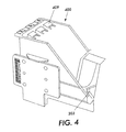
- Fig. 4 shows the ink tank receptacle 400 which is designed to accept an ink tank 100 or 300 with or without an emulation element 200, with an emulation element 207 being inserted into the print head 400.
- the ink tank receptacle 400 is also designed to accept the emulation element 200 with or without an ink tank 100 or 300.
- Fig. 4 shows the relative dimensions of the ink tank receptacle 400 and of the emulation element 200, and shows an emulation element 200 inserted into an ink tank receptacle separate and apart from an ink tank 100.
- the ink tank emulation element 200 By inserting an ink tank emulation element 200 by itself into an ink tank receptacle 400, the ink tank emulation element 200 can be tested, and any desired changes or adjustments to the feature 201, the feature 203, the feature 205 and for the feature 207 can be made.
- an ink identification indicator 207 such as, for example, a label, can be changed and tested. Of course, such testing can take place while an emulation element 200 is attached to an ink tank 100.
- Figs. 5 and 6 show a front plan view and a bottom perspective view, respectively, of the structural details of three emulation elements 200 in a side-by-side arrangement. These emulation elements 200 may be separate from each other or may be joined together. Each emulation element 200 can contain one or more of a toe portion 205, an ink identification feature 201, an ink level viewer and indicator 203 and an ink tank brand indicator 207. Depending on the ink tank receptacle, only one of each of these features may be desirable, or multiple instances of one or more of these features may be desirable.
- the emulation elements according to this invention allow any ink tank to appear to be the type that is to be appropriately installed into a given ink tank receptacle in a print engine.
- the emulation elements according to this invention also allow one device, an ink tank with the emulator element, to appear as if that device were another device, such as, for example, an appropriate ink tank designed to be used with a particular ink tank receptacle in a particular print engine.
Landscapes
- Ink Jet (AREA)
Abstract
Description
Claims (10)
- An emulator attachable to an ink tank usable in a print engine that senses at least one sensible feature of an installed ink tank, comprising:an emulation element, distinct from the ink tank, having at least one of the at least one sensible feature, such that, when the emulation element is attached to the ink tank, the ink tank is rendered usable in the print engine.
- The emulator of claim 1, further comprising an ink tank combined with the emulator.
- The emulator of claim 2, further comprising an ink tank receptacle configured to accept the emulator combined with the ink tank.
- The emulator of claim 1, further comprising an ink tank receptacle combined with said emulator.
- The emulator of claim 1, wherein the at least one sensible feature of the emulation element comprises an ink identification element.
- The emulator of claim 1, wherein the at least one sensible feature of the emulation element comprises an ink level viewing element.
- The emulator of claim 1, wherein the at least one sensible feature of the emulation element comprises an ink level indicator.
- The emulator of claim 1, wherein the at least one sensible feature of the emulation element comprises at least one mating and/or keying structure.
- A method of permitting an ink tank to operate in a print engine that requires an appropriate ink tank to have at least one sensible feature, comprising:associating an emulation element with an ink tank that lacks at least one of the at least one sensible feature, the emulation element including the at least one of the least one sensible feature lacked by the ink tank; andinstalling the ink tank and the associated emulation element in the print engine, such that the print engine senses all of the at least one sensible features required by the print engine.
- The method of claim 9, further comprising attaching the ink tank and the emulation element to each other.
Applications Claiming Priority (2)
| Application Number | Priority Date | Filing Date | Title |
|---|---|---|---|
| US749562 | 1985-06-27 | ||
| US09/749,562 US7018014B2 (en) | 2000-12-28 | 2000-12-28 | Printing brand sensing bypass using an emulator |
Publications (3)
| Publication Number | Publication Date |
|---|---|
| EP1219438A2 true EP1219438A2 (en) | 2002-07-03 |
| EP1219438A3 EP1219438A3 (en) | 2003-05-28 |
| EP1219438B1 EP1219438B1 (en) | 2006-12-13 |
Family
ID=25014255
Family Applications (1)
| Application Number | Title | Priority Date | Filing Date |
|---|---|---|---|
| EP01130493A Expired - Lifetime EP1219438B1 (en) | 2000-12-28 | 2001-12-20 | Emulator attachable to an ink tank for printing apparatus |
Country Status (4)
| Country | Link |
|---|---|
| US (1) | US7018014B2 (en) |
| EP (1) | EP1219438B1 (en) |
| JP (1) | JP2002211000A (en) |
| DE (1) | DE60125138T2 (en) |
Cited By (6)
| Publication number | Priority date | Publication date | Assignee | Title |
|---|---|---|---|---|
| EP1424202A1 (en) * | 2002-11-26 | 2004-06-02 | Seiko Epson Corporation | Ink cartridge and recording apparatus |
| US6863376B2 (en) | 2001-04-03 | 2005-03-08 | Seiko Epson Corporation | Ink cartridge and ink-jet recording apparatus |
| US6955422B2 (en) | 2001-04-03 | 2005-10-18 | Seiko Epson Corporation | Ink cartridge |
| US6979079B2 (en) | 2002-11-26 | 2005-12-27 | Seiko Epson Corporation | Ink cartridge and recording apparatus |
| WO2006032185A1 (en) * | 2004-09-25 | 2006-03-30 | Print-Rite Technology Development Co., Ltd Of Zhuhai | Ink cartridge |
| US7625060B2 (en) * | 2002-09-24 | 2009-12-01 | Seiko Epson Corporation | Cartridge, printing apparatus, and method of transmitting information to and from cartridge |
Families Citing this family (5)
| Publication number | Priority date | Publication date | Assignee | Title |
|---|---|---|---|---|
| CN100411874C (en) * | 2004-09-25 | 2008-08-20 | 珠海天威技术开发有限公司 | Replacement type constant pressure ink cartridge and using method thereof |
| JP2007105704A (en) * | 2005-10-17 | 2007-04-26 | Seiko Epson Corp | Head cap, suction unit, droplet discharge device, method of manufacturing electro-optical device, electro-optical device, and electronic apparatus |
| JP4719050B2 (en) * | 2006-03-30 | 2011-07-06 | Ntn株式会社 | Pattern correction device and application unit thereof |
| US20080259112A1 (en) * | 2007-04-20 | 2008-10-23 | David Olsen | Printing device having supply of colorant that is non-refillable and at least substantially non-removable from end user perspective |
| PL2397329T3 (en) * | 2010-06-17 | 2013-04-30 | Brother Ind Ltd | Recording apparatus and ink cartridge |
Family Cites Families (14)
| Publication number | Priority date | Publication date | Assignee | Title |
|---|---|---|---|---|
| US4853708A (en) * | 1988-03-03 | 1989-08-01 | Eastman Kodak Company | Ink cartridge and housing construction for multicolor ink jet printing apparatus |
| DE69033928T2 (en) | 1989-08-05 | 2002-07-18 | Canon K.K., Tokio/Tokyo | Ink jet recording apparatus and ink cartridge therefor |
| JP3222454B2 (en) * | 1990-02-02 | 2001-10-29 | キヤノン株式会社 | Ink tank cartridge |
| JP3167789B2 (en) * | 1992-06-03 | 2001-05-21 | キヤノン株式会社 | INK JET RECORDING APPARATUS AND INK REMAINING LOW DETECTION METHOD |
| SG75088A1 (en) * | 1993-04-30 | 2000-09-19 | Hewlett Packard Co | Common ink-jet cartridge platform for different printheads |
| US5519422A (en) | 1993-05-03 | 1996-05-21 | Hewlett-Packard Company | Method and device for preventing unintended use of print cartridges |
| US6142617A (en) | 1995-04-27 | 2000-11-07 | Hewlett-Packard Company | Ink container configured for use with compact supply station |
| FR2744391B1 (en) | 1996-02-01 | 1998-03-06 | Imaje Sa | INDUSTRIAL PRINTER CAPABLE OF RECEIVING AT LEAST ONE CONSUMABLE CARTRIDGE |
| JP3413052B2 (en) | 1996-04-23 | 2003-06-03 | キヤノン株式会社 | Ink jet recording apparatus and control method |
| US6068371A (en) | 1997-09-22 | 2000-05-30 | Owens-Illinois Closure Inc. | Liquid containment and dispensing device with improved position indicating indicia |
| US6039430A (en) * | 1998-06-05 | 2000-03-21 | Hewlett-Packard Company | Method and apparatus for storing and retrieving information on a replaceable printing component |
| US6224192B1 (en) | 1998-10-06 | 2001-05-01 | Hewlett-Packard Company | Inkjet printing systems using a modular print cartridge assembly |
| US6151041A (en) | 1998-10-19 | 2000-11-21 | Lexmark International, Inc. | Less restrictive print head cartridge installation in an ink jet printer |
| US6325495B1 (en) * | 1999-12-08 | 2001-12-04 | Pitney Bowes Inc. | Method and apparatus for preventing the unauthorized use of a retaining cartridge |
-
2000
- 2000-12-28 US US09/749,562 patent/US7018014B2/en not_active Expired - Fee Related
-
2001
- 2001-12-20 DE DE60125138T patent/DE60125138T2/en not_active Expired - Lifetime
- 2001-12-20 EP EP01130493A patent/EP1219438B1/en not_active Expired - Lifetime
- 2001-12-21 JP JP2001388703A patent/JP2002211000A/en active Pending
Cited By (26)
| Publication number | Priority date | Publication date | Assignee | Title |
|---|---|---|---|---|
| US7178902B2 (en) | 2001-04-03 | 2007-02-20 | Seiko Epson Corporation | Ink cartridge and ink-jet recording apparatus |
| US7566112B2 (en) | 2001-04-03 | 2009-07-28 | Seiko Epson Corporation | Ink cartridge and ink-jet recording apparatus |
| US7934794B2 (en) | 2001-04-03 | 2011-05-03 | Seiko Epson Corporation | Ink cartridge |
| US7934822B2 (en) | 2001-04-03 | 2011-05-03 | Seiko Epson Corporation | Ink cartridge |
| US6863376B2 (en) | 2001-04-03 | 2005-03-08 | Seiko Epson Corporation | Ink cartridge and ink-jet recording apparatus |
| US7237882B2 (en) | 2001-04-03 | 2007-07-03 | Seiko Epson Corporation | Ink cartridge having retaining structure and recording apparatus for receiving the ink cartridge |
| US6955422B2 (en) | 2001-04-03 | 2005-10-18 | Seiko Epson Corporation | Ink cartridge |
| US7614732B2 (en) | 2001-04-03 | 2009-11-10 | Seiko Epson Corporation | Ink cartridge |
| US7325915B2 (en) | 2001-04-03 | 2008-02-05 | Seiko Epson Corporation | Ink cartridge having retaining structure |
| US7018030B2 (en) | 2001-04-03 | 2006-03-28 | Seiko Epson Corporation | Ink cartridge and ink-jet recording apparatus |
| US7625060B2 (en) * | 2002-09-24 | 2009-12-01 | Seiko Epson Corporation | Cartridge, printing apparatus, and method of transmitting information to and from cartridge |
| EP1586452A1 (en) * | 2002-11-26 | 2005-10-19 | Seiko Epson Corporation | Ink cartridge and identification block |
| US7237883B2 (en) | 2002-11-26 | 2007-07-03 | Seiko Epson Corporation | Ink cartridge having positioning structure and recording apparatus for receiving the ink cartridge |
| US7686441B2 (en) | 2002-11-26 | 2010-03-30 | Seiko Epson Corporation | Ink cartridge and recording apparatus |
| CN1919613B (en) * | 2002-11-26 | 2012-08-08 | 精工爱普生株式会社 | Ink cartridge |
| US7244018B2 (en) | 2002-11-26 | 2007-07-17 | Seiko Epson Corporation | Ink cartridge having retaining structure and memory |
| US7008053B2 (en) | 2002-11-26 | 2006-03-07 | Seiko Epson Corporation | Ink cartridge and recording apparatus |
| AU2003244220B2 (en) * | 2002-11-26 | 2009-02-19 | Seiko Epson Corporation | Ink Cartridge and Recording Apparatus |
| FR2848144A1 (en) * | 2002-11-26 | 2004-06-11 | Seiko Epson Corp | INK CARTRIDGE AND RECORDING APPARATUS |
| US6979079B2 (en) | 2002-11-26 | 2005-12-27 | Seiko Epson Corporation | Ink cartridge and recording apparatus |
| EP1424202A1 (en) * | 2002-11-26 | 2004-06-02 | Seiko Epson Corporation | Ink cartridge and recording apparatus |
| US7669993B2 (en) | 2002-11-26 | 2010-03-02 | Seiko Epson Corporation | Ink cartridge and recording apparatus |
| GB2402368B (en) * | 2002-11-26 | 2005-06-08 | Seiko Epson Corp | Ink cartridge and recording apparatus |
| GB2402368A (en) * | 2002-11-26 | 2004-12-08 | Seiko Epson Corp | Ink cartridge having identification block |
| FR2854344A1 (en) * | 2002-11-26 | 2004-11-05 | Seiko Epson Corp | INK CARTRIDGE AND RECORDING APPARATUS |
| WO2006032185A1 (en) * | 2004-09-25 | 2006-03-30 | Print-Rite Technology Development Co., Ltd Of Zhuhai | Ink cartridge |
Also Published As
| Publication number | Publication date |
|---|---|
| DE60125138D1 (en) | 2007-01-25 |
| US7018014B2 (en) | 2006-03-28 |
| DE60125138T2 (en) | 2007-04-12 |
| EP1219438A3 (en) | 2003-05-28 |
| EP1219438B1 (en) | 2006-12-13 |
| JP2002211000A (en) | 2002-07-31 |
| US20020085049A1 (en) | 2002-07-04 |
Similar Documents
| Publication | Publication Date | Title |
|---|---|---|
| US7018014B2 (en) | Printing brand sensing bypass using an emulator | |
| US6857732B2 (en) | Visible identification of solid ink stick | |
| US6047110A (en) | Method and apparatus for identifying a print media type | |
| EP2127884B1 (en) | Ink bag adapter, adapter-equipped ink bag, and printing apparatus | |
| US5540510A (en) | Printing device for receiving at least two different types of tape holding cases | |
| EP1004446A2 (en) | Insertable cartridge for digital camera with ink jet printer | |
| EP0854043A2 (en) | Apparatus controlled by data from consumable parts with incorporated memory devices | |
| EP0881599A3 (en) | Disabling a mailing machine when a print head is not installed | |
| JP2003312013A (en) | Solid ink stick | |
| US20020043173A1 (en) | Printer diagnosis device, printer diagnosis method, and computer-readable program storage medium containing program having printer diagnosis function | |
| EP0875862A3 (en) | Postage meter with removable print head | |
| US7248809B2 (en) | Method of indicating a paper insertion direction and a printer driver using the same | |
| US20130099142A1 (en) | Top of form sensor | |
| JPS63147649A (en) | Ink jet printer | |
| US8025385B2 (en) | Ink sticks with visually discernible feature patterns | |
| US6868462B2 (en) | Intermediate resource management device | |
| EP1059169A1 (en) | Method and apparatus for detecting ink tank characteristics | |
| US20100278544A1 (en) | System and method for ensuring that only a specific toner is used for printing a document | |
| JP2001121795A (en) | Image forming device | |
| US20040080774A1 (en) | Printing after consumable exhaustion | |
| US7500741B2 (en) | Expendable part, expendable part installation structure, and imaging apparatus | |
| JP2002011928A (en) | Self-diagnosis device, self-diagnosis method, and computer-readable program storage medium storing program having self-diagnosis function | |
| JP2019162813A (en) | Printer and method for controlling printer | |
| PRINTER et al. | FUJITSU DL1200 | |
| JPH02164581A (en) | Recording paper |
Legal Events
| Date | Code | Title | Description |
|---|---|---|---|
| PUAI | Public reference made under article 153(3) epc to a published international application that has entered the european phase |
Free format text: ORIGINAL CODE: 0009012 |
|
| AK | Designated contracting states |
Kind code of ref document: A2 Designated state(s): AT BE CH CY DE DK ES FI FR GB GR IE IT LI LU MC NL PT SE TR |
|
| AX | Request for extension of the european patent |
Free format text: AL;LT;LV;MK;RO;SI |
|
| PUAL | Search report despatched |
Free format text: ORIGINAL CODE: 0009013 |
|
| AK | Designated contracting states |
Designated state(s): AT BE CH CY DE DK ES FI FR GB GR IE IT LI LU MC NL PT SE TR |
|
| AX | Request for extension of the european patent |
Extension state: AL LT LV MK RO SI |
|
| 17P | Request for examination filed |
Effective date: 20031128 |
|
| AKX | Designation fees paid |
Designated state(s): DE FR GB |
|
| 17Q | First examination report despatched |
Effective date: 20040308 |
|
| GRAP | Despatch of communication of intention to grant a patent |
Free format text: ORIGINAL CODE: EPIDOSNIGR1 |
|
| GRAS | Grant fee paid |
Free format text: ORIGINAL CODE: EPIDOSNIGR3 |
|
| GRAC | Information related to communication of intention to grant a patent modified |
Free format text: ORIGINAL CODE: EPIDOSCIGR1 |
|
| GRAA | (expected) grant |
Free format text: ORIGINAL CODE: 0009210 |
|
| AK | Designated contracting states |
Kind code of ref document: B1 Designated state(s): DE FR GB |
|
| REG | Reference to a national code |
Ref country code: GB Ref legal event code: FG4D |
|
| REF | Corresponds to: |
Ref document number: 60125138 Country of ref document: DE Date of ref document: 20070125 Kind code of ref document: P |
|
| ET | Fr: translation filed | ||
| PLBE | No opposition filed within time limit |
Free format text: ORIGINAL CODE: 0009261 |
|
| STAA | Information on the status of an ep patent application or granted ep patent |
Free format text: STATUS: NO OPPOSITION FILED WITHIN TIME LIMIT |
|
| 26N | No opposition filed |
Effective date: 20070914 |
|
| REG | Reference to a national code |
Ref country code: FR Ref legal event code: PLFP Year of fee payment: 15 |
|
| REG | Reference to a national code |
Ref country code: FR Ref legal event code: PLFP Year of fee payment: 16 |
|
| PGFP | Annual fee paid to national office [announced via postgrant information from national office to epo] |
Ref country code: FR Payment date: 20161121 Year of fee payment: 16 Ref country code: GB Payment date: 20161128 Year of fee payment: 16 Ref country code: DE Payment date: 20161121 Year of fee payment: 16 |
|
| REG | Reference to a national code |
Ref country code: DE Ref legal event code: R119 Ref document number: 60125138 Country of ref document: DE |
|
| GBPC | Gb: european patent ceased through non-payment of renewal fee |
Effective date: 20171220 |
|
| REG | Reference to a national code |
Ref country code: FR Ref legal event code: ST Effective date: 20180831 |
|
| PG25 | Lapsed in a contracting state [announced via postgrant information from national office to epo] |
Ref country code: DE Free format text: LAPSE BECAUSE OF NON-PAYMENT OF DUE FEES Effective date: 20180703 Ref country code: FR Free format text: LAPSE BECAUSE OF NON-PAYMENT OF DUE FEES Effective date: 20180102 |
|
| PG25 | Lapsed in a contracting state [announced via postgrant information from national office to epo] |
Ref country code: GB Free format text: LAPSE BECAUSE OF NON-PAYMENT OF DUE FEES Effective date: 20171220 |