EP1219362A1 - Apparatus for treating garbage - Google Patents
Apparatus for treating garbage Download PDFInfo
- Publication number
- EP1219362A1 EP1219362A1 EP00940883A EP00940883A EP1219362A1 EP 1219362 A1 EP1219362 A1 EP 1219362A1 EP 00940883 A EP00940883 A EP 00940883A EP 00940883 A EP00940883 A EP 00940883A EP 1219362 A1 EP1219362 A1 EP 1219362A1
- Authority
- EP
- European Patent Office
- Prior art keywords
- solid
- treatment apparatus
- waste
- containers
- waste treatment
- Prior art date
- Legal status (The legal status is an assumption and is not a legal conclusion. Google has not performed a legal analysis and makes no representation as to the accuracy of the status listed.)
- Withdrawn
Links
Images


Classifications
-
- C—CHEMISTRY; METALLURGY
- C05—FERTILISERS; MANUFACTURE THEREOF
- C05F—ORGANIC FERTILISERS NOT COVERED BY SUBCLASSES C05B, C05C, e.g. FERTILISERS FROM WASTE OR REFUSE
- C05F7/00—Fertilisers from waste water, sewage sludge, sea slime, ooze or similar masses
-
- B—PERFORMING OPERATIONS; TRANSPORTING
- B09—DISPOSAL OF SOLID WASTE; RECLAMATION OF CONTAMINATED SOIL
- B09B—DISPOSAL OF SOLID WASTE NOT OTHERWISE PROVIDED FOR
- B09B3/00—Destroying solid waste or transforming solid waste into something useful or harmless
- B09B3/30—Destroying solid waste or transforming solid waste into something useful or harmless involving mechanical treatment
- B09B3/35—Shredding, crushing or cutting
-
- B—PERFORMING OPERATIONS; TRANSPORTING
- B03—SEPARATION OF SOLID MATERIALS USING LIQUIDS OR USING PNEUMATIC TABLES OR JIGS; MAGNETIC OR ELECTROSTATIC SEPARATION OF SOLID MATERIALS FROM SOLID MATERIALS OR FLUIDS; SEPARATION BY HIGH-VOLTAGE ELECTRIC FIELDS
- B03B—SEPARATING SOLID MATERIALS USING LIQUIDS OR USING PNEUMATIC TABLES OR JIGS
- B03B9/00—General arrangement of separating plant, e.g. flow sheets
- B03B9/06—General arrangement of separating plant, e.g. flow sheets specially adapted for refuse
-
- B—PERFORMING OPERATIONS; TRANSPORTING
- B09—DISPOSAL OF SOLID WASTE; RECLAMATION OF CONTAMINATED SOIL
- B09B—DISPOSAL OF SOLID WASTE NOT OTHERWISE PROVIDED FOR
- B09B3/00—Destroying solid waste or transforming solid waste into something useful or harmless
- B09B3/60—Biochemical treatment, e.g. by using enzymes
-
- C—CHEMISTRY; METALLURGY
- C02—TREATMENT OF WATER, WASTE WATER, SEWAGE, OR SLUDGE
- C02F—TREATMENT OF WATER, WASTE WATER, SEWAGE, OR SLUDGE
- C02F3/00—Biological treatment of water, waste water, or sewage
- C02F3/02—Aerobic processes
- C02F3/10—Packings; Fillings; Grids
- C02F3/101—Arranged-type packing, e.g. stacks, arrays
-
- C—CHEMISTRY; METALLURGY
- C05—FERTILISERS; MANUFACTURE THEREOF
- C05F—ORGANIC FERTILISERS NOT COVERED BY SUBCLASSES C05B, C05C, e.g. FERTILISERS FROM WASTE OR REFUSE
- C05F9/00—Fertilisers from household or town refuse
- C05F9/02—Apparatus for the manufacture
-
- C—CHEMISTRY; METALLURGY
- C12—BIOCHEMISTRY; BEER; SPIRITS; WINE; VINEGAR; MICROBIOLOGY; ENZYMOLOGY; MUTATION OR GENETIC ENGINEERING
- C12M—APPARATUS FOR ENZYMOLOGY OR MICROBIOLOGY; APPARATUS FOR CULTURING MICROORGANISMS FOR PRODUCING BIOMASS, FOR GROWING CELLS OR FOR OBTAINING FERMENTATION OR METABOLIC PRODUCTS, i.e. BIOREACTORS OR FERMENTERS
- C12M25/00—Means for supporting, enclosing or fixing the microorganisms, e.g. immunocoatings
- C12M25/16—Particles; Beads; Granular material; Encapsulation
-
- C—CHEMISTRY; METALLURGY
- C12—BIOCHEMISTRY; BEER; SPIRITS; WINE; VINEGAR; MICROBIOLOGY; ENZYMOLOGY; MUTATION OR GENETIC ENGINEERING
- C12M—APPARATUS FOR ENZYMOLOGY OR MICROBIOLOGY; APPARATUS FOR CULTURING MICROORGANISMS FOR PRODUCING BIOMASS, FOR GROWING CELLS OR FOR OBTAINING FERMENTATION OR METABOLIC PRODUCTS, i.e. BIOREACTORS OR FERMENTERS
- C12M27/00—Means for mixing, agitating or circulating fluids in the vessel
- C12M27/02—Stirrer or mobile mixing elements
- C12M27/06—Stirrer or mobile mixing elements with horizontal or inclined stirrer shaft or axis
-
- C—CHEMISTRY; METALLURGY
- C12—BIOCHEMISTRY; BEER; SPIRITS; WINE; VINEGAR; MICROBIOLOGY; ENZYMOLOGY; MUTATION OR GENETIC ENGINEERING
- C12M—APPARATUS FOR ENZYMOLOGY OR MICROBIOLOGY; APPARATUS FOR CULTURING MICROORGANISMS FOR PRODUCING BIOMASS, FOR GROWING CELLS OR FOR OBTAINING FERMENTATION OR METABOLIC PRODUCTS, i.e. BIOREACTORS OR FERMENTERS
- C12M45/00—Means for pre-treatment of biological substances
- C12M45/04—Phase separators; Separation of non fermentable material; Fractionation
-
- Y—GENERAL TAGGING OF NEW TECHNOLOGICAL DEVELOPMENTS; GENERAL TAGGING OF CROSS-SECTIONAL TECHNOLOGIES SPANNING OVER SEVERAL SECTIONS OF THE IPC; TECHNICAL SUBJECTS COVERED BY FORMER USPC CROSS-REFERENCE ART COLLECTIONS [XRACs] AND DIGESTS
- Y02—TECHNOLOGIES OR APPLICATIONS FOR MITIGATION OR ADAPTATION AGAINST CLIMATE CHANGE
- Y02A—TECHNOLOGIES FOR ADAPTATION TO CLIMATE CHANGE
- Y02A40/00—Adaptation technologies in agriculture, forestry, livestock or agroalimentary production
- Y02A40/10—Adaptation technologies in agriculture, forestry, livestock or agroalimentary production in agriculture
- Y02A40/20—Fertilizers of biological origin, e.g. guano or fertilizers made from animal corpses
-
- Y—GENERAL TAGGING OF NEW TECHNOLOGICAL DEVELOPMENTS; GENERAL TAGGING OF CROSS-SECTIONAL TECHNOLOGIES SPANNING OVER SEVERAL SECTIONS OF THE IPC; TECHNICAL SUBJECTS COVERED BY FORMER USPC CROSS-REFERENCE ART COLLECTIONS [XRACs] AND DIGESTS
- Y02—TECHNOLOGIES OR APPLICATIONS FOR MITIGATION OR ADAPTATION AGAINST CLIMATE CHANGE
- Y02W—CLIMATE CHANGE MITIGATION TECHNOLOGIES RELATED TO WASTEWATER TREATMENT OR WASTE MANAGEMENT
- Y02W10/00—Technologies for wastewater treatment
- Y02W10/10—Biological treatment of water, waste water, or sewage
-
- Y—GENERAL TAGGING OF NEW TECHNOLOGICAL DEVELOPMENTS; GENERAL TAGGING OF CROSS-SECTIONAL TECHNOLOGIES SPANNING OVER SEVERAL SECTIONS OF THE IPC; TECHNICAL SUBJECTS COVERED BY FORMER USPC CROSS-REFERENCE ART COLLECTIONS [XRACs] AND DIGESTS
- Y02—TECHNOLOGIES OR APPLICATIONS FOR MITIGATION OR ADAPTATION AGAINST CLIMATE CHANGE
- Y02W—CLIMATE CHANGE MITIGATION TECHNOLOGIES RELATED TO WASTEWATER TREATMENT OR WASTE MANAGEMENT
- Y02W30/00—Technologies for solid waste management
- Y02W30/50—Reuse, recycling or recovery technologies
- Y02W30/52—Mechanical processing of waste for the recovery of materials, e.g. crushing, shredding, separation or disassembly
Definitions
- the present invention relates to a waste treatment apparatus comprising a solid-liquid separating device for separating a mixture composed of a solid substance and a liquid substance, the solid-liquid separating device subjecting the mixture to filtering to discharge organic waste water while decomposing organic solid substances by the action of microorganisms existing in the organic solid substance.
- an activated sludge method is usually used in sewage treatment plants, and a submerged infiltration bed is used along with the activated sludge method in combined waste water purifying tanks.
- Japanese Patent Laid-Open Publication No. Hei 9-1117 discloses an apparatus in which waste water containing garbage is introduced into a solid substance treating section which decomposes a solid substance by means of microorganisms and discharges primary treated water, which is then introduced into a waste water treating tank for aeration. In this manner, solid substances are decomposed and removed from the waste water containing garbage from the garbage disposal, and the waste water is purified.
- waste water is subjected to aeration by an air diffuser in the waste water treating tank, which is a treatment basically similar to the activated sludge method.
- the present inventors found that more effective purification of waste water can be performed when a waste water treating device (a secondary treating device) comprising a packed layer which is packed with microorganism carriers is provided downstream of the solid substance treating device (a primary treating device). (See Japanese Patent Laid-Open Publication No. Hei 11-19674)
- air is circulated using a gas supply member, such that the optimal oxygen concentration for the aerobic treatment is maintained in the microorganism carriers.
- a gas supply member such that the optimal oxygen concentration for the aerobic treatment is maintained in the microorganism carriers.
- an air pump and a support layer or the like into which air is forced by the gas supply member must be provided, and this disadvantageously increases the apparatus in size.
- the present invention was conceived in view of the aforementioned problems of the related art and aims to provide an apparatus for treating garbage, or a waste treatment apparatus, capable of effectively treating organic waste water such as the output of a garbage disposal or other kitchen waste water, by means of an aerobic treatment using natural diffusion of oxygen.
- a waste treatment apparatus comprises a disposal for mechanically reducing waste discharged from a kitchen; a flow rate controlling tank for temporarily storing a mixture of the waste reduced by said disposal and kitchen waste water; a solid-liquid separating device for separating the mixture supplied from the flow rate controlling tank into a solid component and a liquid component; a composting device for converting the solid component separated by the solid-liquid separating device into a compost; a precipitation-separation tank for precipitating fine particles in the liquid component supplied from the solid-liquid separating device; a split-flow device for distributing the liquid component supplied from the precipitation-separation tank; and a waste water treating device for biologically treating the liquid part supplied from the split-flow device to thereby produce treated water.
- Said waste water treating device may comprise a tank containing microorganism carriers, and said liquid component may be introduced into the tank wherein it is subjected to a biological treatment, and from which it is then discharged out of said garbage treating apparatus.
- Said waste water treating device may have perforated containers which contain said microorganism carriers.
- Said waste water treating device may comprises a plurality of said perforated containers.
- Said perforated containers may be in contact with one another.
- Said microorganism carriers may have different average grain sizes and be alternately stacked in said containers.
- Said microorganism carriers may have different average grain sizes and be concentrically packed in said containers.
- the ratio of diameter of said microorganism carriers having different average grain size may preferably be 1 : 1.5 - 2.5.
- Said microorganism carriers may be wood chips.
- Said containers may be mesh baskets.
- the mesh size (air gap) of said mesh baskets may preferably be 3 mm - 7 mm.
- Said containers may be unglazed containers.
- Said split-flow device may include a cleaning device, and waste water from the cleaning device may be returned to the flow rate controlling tank or the precipitation-separation tank.
- Fig. 1 shows the structure of a waste treatment system according to the present embodiment, the system being connected to a kitchen counter.
- the waste treatment system comprises a disposal 200 for finely grinding, mulching, or similarly reducing into a fine composition waste discharged from a sink 100 of the kitchen counter 100; a flow rate controlling tank 300 into which flows a mixture from the disposal of a solid substance such as ground garbage or the like and a liquid substance such as kitchen waste water or the like ; a solid-liquid separating device 400 for separating the mixture into a solid substance and a liquid substance; a precipitation-separation tank 700 for precipitating fine particles in the liquid component; a split-flow device 800 for distributing a supernatant (which will be described later) pumped from the precipitation-separation tank 700; a secondary treating device 500 for performing a purification treatment of the liquid substance; and a solid substance treating device (composting device) 600 for composting the solid substance.
- a disposal 200 for finely grinding, mulching, or similarly reducing into a fine composition waste discharged from a sink 100 of the kitchen counter 100
- a flow rate controlling tank 300 into which flows
- the disposal 200 which includes an electromagnetic valve 202 and a start switch 203, is disposed under the sink 101 while the solid-liquid separating device 400, the precipitation tank 700, the split-flow device 800, the secondary treating device 500 and the solid substance treating device 600 are housed in a body case (not shown) and is located outside the house.
- the mixture discharged from the disposal 200 is temporarily introduced into the flow rate controlling tank 300 through an introduction pipe 201.
- the start switch When only water, which is harmless to the environment when discharged into sewerage, is to be directly discharged through the discharge pipe 204, the start switch is turned OFF to inhibit start of the disposal 200.
- the electromagnetic valve 202 then causes the disposal 200 and the discharge pipe 204 to communicate each other, so that water from the sink 101 is discharged into sewerage.
- the start switch 203 is turned ON to start the disposal 200.
- the electromagnetic valve 202 then causes the disposal 200 and the introduction pipe 201 to communicate with each other, so that composting and purification, as will be described later, is performed.
- the flow rate controlling tank 300 comprises a storage tank 301 for storing the mixture introduced through the introduction pipe 201, a solid substance transporting air lift pump 304 for transporting the mixture mainly composed of solid substances existing at the base portion of the storage tank 301 to the solid-liquid separating device 400 through the pipe 303, and a water level sensor 306 for detecting the water level of the mixture stored the storage tank 301.
- the air lift pump 304 comprises a blower 302 for blowing air for lifting and the air lift pipe 303 into the bottom of which air is supplied from the blower 302, so that the air lift pump 304 transfers the solid substances at the lower part of the air lift pipe 303 upward, together with the liquid, to the upper end portion, from which the liquid and solid are supplied to the solid-liquid separating device 400.
- the driving period of the air lift pump 304 or the amount of air supplied to the air lift pump 304 is controlled in order to supply a substantially constant amount of solid substances and liquid to the solid-liquid separating device 400 regardless of the water level of the storage tank 301.
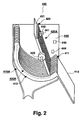
- the solid-liquid separating device 400 comprises a first slit portion 410A having a great number of drain slots 411 formed therein, a transport portion 420A for transporting the mixture having been subjected to solid-liquid separation, a second slit portion 430A which is connected to an end of the transport portion such that it can swing between the drain slots for accelerating solid-liquid separation of the introduced mixture, and a position detection portion 440 for detecting the position of the transport portion 420A.
- the first slit portion 410A, the transport portion 420A, and the second slit portion 430A are integrally resin molded by plastic or the like.
- the first slit portion 410A has arc-shaped drain teeth 412 for screening and draining the mixture of solid and liquid introduced through the introduction pipe 201, and an introduction plate 413 for guiding the solid substances to the solid substance treating device 600 by causing the mixture having been subjected to draining (namely, solid substances in this case) to slide along the upper surface.
- Each of the drain slots 411 is formed between the drain teeth 412.
- the transport portion 420A is fixed to a rotation shaft 423 coupled to a motor (not shown), and is composed of a transport plate 421 for transporting solid substances and ribs 422 provided on the rear surface of the transport plate 421.
- the ribs 422 are provided so as to provide the transport plate 421, which is formed of a thin plastic material, with sufficient strength to resist deformation.
- the mixture is transported through the air lift pump 304 to the portion of the transport portion 420A shown on the left side of the drawing, where liquid drips down through the drain slots 411 while the solid substances are accumulated on the drain teeth 412.
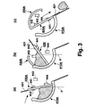
- the second slit portion 430A connected to end portion of the transport portion 420A is disposed within the drain slots 411, and swings within the drain slots 411 in accordance with the swinging movement of the transport portion 420A. In other words, by rotating the transport portion 420A back and forth within a predetermined angular range, the second slit portion 430A is also made to rotate, to thereby stir the solid substances on the drain teeth 412 for promoting the draining process.
- numeral 700 denotes the precipitation-separation tank 700 which precipitates fine particulate from the liquid component supplied from the solid-liquid separating device 400
- numeral 500 denotes the secondary treating device functioning as an organic waste water treating device for treating organic waste water (primary treated water) which is discharged from the solid-liquid separating device 400.
- a supernatant obtained by precipitation separation in the precipitation-separation tank 700 is supplied to the secondary treating device 500.
- precipitants accumulated at the bottom of the precipitation-separation tank 700 are appropriately returned to the flow rate controlling tank 300.
- the split-flow device 800 distributes the supernatant supplied from the precipitation-separation tank 700 into the secondary treating device 500.
- the supplied liquid is evenly divided into split flows by means of an overflow weir having a plurality of triangular cut portions formed therein.
- the secondary treating device 500 has at least two perforated cylindrical mesh basket containers 510a, 510b having a diameter of 15 cm, the mesh basket containers vertically arranged in contact with each other.
- the mesh basket containers vertically arranged in contact with each other.
- four containers 510a and three containers 510b are alternatively stacked, the total heights of a container 510a and a container 510b being approximately 15 cm, and the stacks are arranged in three parallel rows.
- the purpose for vertically arranging the cylindrical mesh basket containers 510a, 510b in upper and lower levels in contact with each other is as follows.
- the container 510a at the upper level will eventually become clogged with solid substances, thereby preventing water from flowing through the container.
- maintenance of the containers is necessary.
- the container 510a at the upper level is replaced by the container 510b at the lower level, and a new microorganism carrier is supplied at the lower level.
- the vertical two-level arrangement according to the present embodiment facilitates such maintenance.
- a new container 510b is added at the lowermost level while the container 510a at the uppermost level is removed.
- any number (2 or more) of levels of the cylindrical containers 510a, 510b may be provided for similarly achieving the effects of the present invention.
- the ratio of the average grain size of the microorganism carriers within the cylindrical containers 510a and 510b is set to 1 : 1.5 ⁇ 2.5, because when the ratio is greater than 1 : 1.5 - 2.5 there is a possibility that a microorganisms carrier having a smaller average grain size would enter a microorganism carrier having a larger average grain size.
- FIG. 4 comparison results are shown for the decomposing ability and an air amount (an air gap amount) for each layer (each container) between (a) the secondary treating device 500 comprising a plurality of cylindrical mesh basket containers according to the present invention and (b) a secondary treating device 500 comprising a plurality of cylindrical mesh basket containers according to a prior art (b).
- the secondary treating device 500 which comprises only dense microorganism carriers contains a small amount of air, and therefore activation of the microorganisms decreases near the center part of the secondary treating device 500, which leads to exhibit a low ability for treating microorganisms.
- the present invention (a) comprising alternate arrangement of dense and coarse microorganism carriers, although the dense microorganism carrier part contains a smaller amount of air, the coarse microorganism carrier part contains a larger amount of air, and therefore a larger amount of air is contained even at the center part of the secondary treating device 500. As a result, activation of the microorganisms is accelerated to increase treating ability for the microorganisms.
- All the containers are packed with wood chips (microorganism carriers) composed of shavings of Japanese cedar, so that the secondary treating device 500 subjects organic components within the introduced organic waste water to an oxidation decomposing treatment by means of aerobic microorganisms living in the carriers.
- wood chips microorganism carriers
- the mesh size (a gap) of the cylindrical mesh basket containers 510a, 510b is 3 ⁇ 7 mm, preferably 5 mm, and the size of wood chip is 2 ⁇ 10 mm.
- the bottom 5 cm are packed with wood chips of 5 - 10 mm size and next 10 cm are packed with 2 ⁇ 4 mm wood chips.
- a central cylindrical (diameter: 5 cm) area in the cylindrical mesh basket containers 510a and 510b is packed with wood chips of 2 ⁇ 4 mm size, and areas above and below are packed with 5 ⁇ 10 mm wood chips.
- containers other than mesh basket containers may be used as the cylindrical containers 510a, 510b, as long as they include holes through which air can pass. Unglazed containers may be used, for example.
- weirs are formed in the split-flow device 800.
- the action of these weirs (cutout portions) allows the primary treated water to be evenly distributed into a plurality of secondary treating devices 500 located below.
- three cutout portions are provided, and a liquid overflowing through respective cutouts is separately extracted so as to obtain evenly split flow.
- the weir (a cutout portion) of the split-flow device 800 is formed by cutting out a triangular piece having each side of 5 cm. It is preferable to appropriately vary the side length of the triangular piece in proportion to an amount of liquid to be supplied from the precipitation-separation tank 700. If the weirs are small even when a large amount of the liquid component is supplied, the liquid would overflow from the split-flow device 800 or the weirs would be clogged with fine particles contained in the liquid supplied from the precipitation-separation tank 700.
- the portion of the split-flow device 800 before the weirs preferably has an inclined bottom so as to allow cleaning when sludge is accumulated thereon, and a pump is provided for pumping the accumulated sludge.
- the waste water after cleaning is returned back to the flow rate controlling tank 300 or the precipitation-separation tank 700.
- a discharge pipe 560 is connected to the bottom of the containers 500 for discharging treated water.
- the primary treated water in the solid-liquid separation device 400 is diffused on the center part of the surface of the cylindrical mesh basket containers 510a, flows downward in contact with the microorganisms which decompose the organic components in the primary treated water, and is finally discharged through the discharge pipe 560 out of the garbage treating apparatus.
- the split-flow device 800 because the supplied liquid is split by the split-flow device 800, the primary treated liquid can be evenly supplied from above the secondary treating device 500. As a result, treatment can be improved by employing the entire secondary treating device 500.
- stacks comprising the mesh basket containers 510a, 510b are provided in three rows, and, therefore, the split-flow device 800 splits the supplied primary treated water into three flows, which are then evenly supplied to the respective mesh basket containers 510a.
- the solid substance treating device 600 comprises a treating tank 610 for storing the solid substances introduced after solid-liquid separation, a stirrer 620 for stirring the solid substances, and a heater or the like (not shown).
- the treating tank 610 contains carriers composed of wood chips or shavings or the like and activated carbon for cultivating microorganisms.
- the microorganisms decompose the solid substances into carbon dioxide and water so as to produce compost.
- the solid substances and the carriers are mixed by the stirrer 620 while air is introduced inside the treating tank 610 which is maintained at a predetermined temperature (30°C ⁇ 40°C in the present embodiment) by the heater, to thereby accelerate activation of the microorganisms or the like.
- the start switch 203 When waste is to be treated, the start switch 203 is turned ON to start the disposal 200. As a result, the electromagnetic valve 202 is operated so that garbage discharged from the sink 101 is ground in the disposal 200 and is then introduced into the storage tank 301 through the introduction pipe 201.
- the introduction pipe 201 By configuring the introduction pipe 201 such that it is inclined by an appropriate amount, it is possible for the pulverized garbage to be transported into the storage tank 301 without employing a separate drive force or the like.
- the start switch 200 When waste treatment is not required (for example, when fresh water is discharged), the start switch 200 is left OFF. In this state, the electromagnetic valve 202 would not operate, so that waste water or the like flows directly into the discharge pipe 204.
- the air lift pump 304 is then driven so that substantially a fixed amount of solid substances and liquid can be supplied to the solid-liquid separating apparatus 400, regardless of the water level of the storage tank 301 detected by the water level sensor 306.
- the mixture containing a large amount of solid substances stored at the bottom of the storage tank 301 is transported through the pipe 303 to the solid-liquid separation device 400 by means of the solid substance transporting air lift pump 304.
- the state of the transport portion 420A of the solid-liquid separating device 400 is as shown in Fig. 2.
- the standby switch 442 is operated by the magnet 441 so that the transport plate 421 awaits introduction of the mixture at a standby position.
- the mixture transported from the flow rate controlling tank 300 contacts the transport plate 421 and loses energy and speed, such that it accumulates on the first slit portion 410A.
- the transport portion 420A and the second slit portion 430A swing back and forth by means a motor (not shown) between the states shown in Fig. 3(a) and Fig. 3(b) by the action of the standby position switch 442 and the swing limit position switch 443.
- This swinging movement causes the agglomeration of the mixture containing the separated solid substances to be stirred for draining, so that solid-liquid separation can be performed with high efficiency.
- the number of swinging movements for each introduction of the mixture can preferably be set to a rate optimized for the introduced substance.
- a range of 5 ⁇ 40 times is preferable.
- the transport portion 420A rotates until the solid substance discharge position switch 444 operates, so that the solid substances separated from the liquid component is placed into the solid substance treating device 600.
- the treating tank 610 of the solid substance treating device 600 contains the carriers composed of wood chips or shavings and activated carbon for cultivating microorganisms.
- the solid substances having been subjected to solid-liquid separation and introduced into the treating tank are decomposed for composting, and then bagged or the like for discharge.
- the solid-liquid separation efficiency of the solid-liquid separating device 400 is improved as described above, so that the treating tank 610 can be downsized and the cost for the whole apparatus can be reduced.
- the present invention provides an advantage in that organic water such as a liquid output from a disposal or kitchen waste water can be effectively treated by means of preferable aerobic treatment using natural diffusion of oxygen and without supplying forced air circulation by an air pump as in the conventional garbage treating apparatus.
Landscapes
- Engineering & Computer Science (AREA)
- Chemical & Material Sciences (AREA)
- Life Sciences & Earth Sciences (AREA)
- Organic Chemistry (AREA)
- Health & Medical Sciences (AREA)
- Zoology (AREA)
- Environmental & Geological Engineering (AREA)
- Bioinformatics & Cheminformatics (AREA)
- Wood Science & Technology (AREA)
- Biochemistry (AREA)
- Microbiology (AREA)
- General Health & Medical Sciences (AREA)
- Sustainable Development (AREA)
- Biotechnology (AREA)
- Biomedical Technology (AREA)
- General Engineering & Computer Science (AREA)
- Genetics & Genomics (AREA)
- General Chemical & Material Sciences (AREA)
- Chemical Kinetics & Catalysis (AREA)
- Molecular Biology (AREA)
- Analytical Chemistry (AREA)
- Biodiversity & Conservation Biology (AREA)
- Hydrology & Water Resources (AREA)
- Water Supply & Treatment (AREA)
- Immunology (AREA)
- Manufacturing & Machinery (AREA)
- Processing Of Solid Wastes (AREA)
- Biological Treatment Of Waste Water (AREA)
- Fertilizers (AREA)
Abstract
Description
Claims (13)
- A waste treatment apparatus comprising:a disposal for mechanically reducing waste discharged from a kitchen;a flow rate controlling tank for temporarily storing a mixture of the waste reduced by said disposal and kitchen waste water;a solid-liquid separating device for separating the mixture supplied from the flow rate controlling tank into a solid component and a liquid component;a composting device for converting the solid component separated by the solid-liquid separating device into a compost;a precipitation-separation tank for precipitating fine particles in the liquid component supplied from the solid-liquid separating device;a split-flow device for distributing the liquid component supplied from the precipitation-separation tank; anda waste water treating device for biologically treating the liquid component supplied from the split-flow device to thereby produce treated water.
- A waste treatment apparatus according to claim 1, wherein
said waste water treating device comprises a tank containing microorganism carriers, and
said liquid component is introduced into the tank, subjected to a biological treatment in the tank, and then discharged out of said waste treatment apparatus. - A waste treatment apparatus according to claim 2, wherein said waste water treating device has perforated containers containing said microorganism carriers.
- A waste treatment apparatus according to claim 3, wherein said waste water treating device comprises a plurality of said perforated containers.
- A waste treatment apparatus according to claim 3 or 4, wherein said perforated containers are in contact with one another.
- A waste treatment apparatus according to any of claims 3 to 5, wherein said microorganism carriers comprise grains of a plurality of average grain sizes which are alternately stacked in said containers.
- A waste treatment apparatus according to any of claims 3 to 5, wherein said microorganism carriers comprise grains of a plurality of average grain sizes which are concentrically packed in said containers.
- A waste treatment apparatus according to any of claims 6 to 7, wherein, in said waste water treating apparatus, the ratio of diameters of said microorganism carriers having different average grain size is 1 : 1.5 - 2.5.
- A waste treatment apparatus according to any of claims 2 to 8, wherein said microorganism carriers are wood chips.
- A waste treatment apparatus according to any of claims 3 to 9, wherein said containers are mesh baskets.
- A waste treatment apparatus according to claim 10, wherein the mesh size (air gap) of said mesh baskets is 3 mm ∼ 7 mm.
- A waste treatment apparatus according to any of claims 3 to 8, wherein said containers are unglazed containers.
- A waste treatment apparatus according to any of claims 1 to 12, wherein said split-flow device includes a cleaning device, and waste water from the cleaning device is returned to the flow rate controlling tank or the precipitation-separation tank.
Applications Claiming Priority (5)
| Application Number | Priority Date | Filing Date | Title |
|---|---|---|---|
| JP18413799 | 1999-06-29 | ||
| JP18413799 | 1999-06-29 | ||
| JP27710299A JP2001070921A (en) | 1999-06-29 | 1999-09-29 | Garbage disposal equipment |
| JP27710299 | 1999-09-29 | ||
| PCT/JP2000/004303 WO2001000342A1 (en) | 1999-06-29 | 2000-06-29 | Apparatus for treating garbage |
Publications (2)
| Publication Number | Publication Date |
|---|---|
| EP1219362A1 true EP1219362A1 (en) | 2002-07-03 |
| EP1219362A4 EP1219362A4 (en) | 2006-02-08 |
Family
ID=26502319
Family Applications (1)
| Application Number | Title | Priority Date | Filing Date |
|---|---|---|---|
| EP00940883A Withdrawn EP1219362A4 (en) | 1999-06-29 | 2000-06-29 | DEVICE FOR TREATING GARBAGE |
Country Status (3)
| Country | Link |
|---|---|
| EP (1) | EP1219362A4 (en) |
| JP (1) | JP2001070921A (en) |
| WO (1) | WO2001000342A1 (en) |
Cited By (5)
| Publication number | Priority date | Publication date | Assignee | Title |
|---|---|---|---|---|
| ES2249960A1 (en) * | 2003-12-10 | 2006-04-01 | Ros Roca Internacional, S.L. | Urban solid waste biomethanisation plant includes a homogenizer and an impurities separator before a clearing tank and a digester |
| EP1658906A1 (en) * | 2004-11-22 | 2006-05-24 | Firma SBM Maschinen GmbH | Process and apparatus for treating biowaste |
| CN101949543A (en) * | 2010-09-17 | 2011-01-19 | 杨长银 | Household garbage treatment system |
| CN102226108A (en) * | 2011-05-04 | 2011-10-26 | 杨长银 | System for converting domestic garbage and solid waste into combustible gas |
| WO2014079910A1 (en) | 2012-11-21 | 2014-05-30 | Tata Steel Ijmuiden B.V. | Chromium-chromium oxide coatings applied to steel substrates for packaging applications and a method for producing said coatings |
Families Citing this family (3)
| Publication number | Priority date | Publication date | Assignee | Title |
|---|---|---|---|---|
| JP2001259672A (en) * | 2000-03-24 | 2001-09-25 | Sanyo Electric Co Ltd | Wastewater treatment equipment and wastewater treatment material recycling method |
| FR2820419B1 (en) * | 2001-02-08 | 2004-01-02 | Univ Limoges | COMPACT DEVICE FOR DECONTAMINATION OF LIQUID EFFLUENTS AT INFECTIOUS RISKS BY PHYSICAL ROUTE |
| CN109351044B (en) * | 2018-12-11 | 2021-12-21 | 安徽天健环保股份有限公司 | Multiphase separation equipment for kitchen waste |
Family Cites Families (8)
| Publication number | Priority date | Publication date | Assignee | Title |
|---|---|---|---|---|
| JPS60222198A (en) * | 1984-04-20 | 1985-11-06 | Matsushita Electric Ind Co Ltd | Treating device for organic waste of apartment house |
| DE3825229A1 (en) * | 1988-07-25 | 1990-02-01 | Wehrle Werk Ag | Process and apparatus for the biological processing of organically polluted liquids |
| JP3429787B2 (en) * | 1992-06-10 | 2003-07-22 | 松下電器産業株式会社 | Method for treating high-concentration organic wastewater and wastewater treatment equipment used for the method |
| JP3429788B2 (en) * | 1992-06-12 | 2003-07-22 | 松下電器産業株式会社 | Wastewater treatment equipment for kitchen waste |
| JPH09240802A (en) * | 1996-03-08 | 1997-09-16 | Shoji Tadokoro | Garbage processing equipment |
| JP2963680B2 (en) * | 1997-08-18 | 1999-10-18 | 西村産業有限会社 | Treatment equipment for treating organic matter contained in liquids with microorganisms |
| JPH11169827A (en) * | 1997-12-09 | 1999-06-29 | Shin Meiwa Ind Co Ltd | Garbage disposal method and apparatus |
| JPH11179384A (en) * | 1997-12-18 | 1999-07-06 | Sanyo Electric Co Ltd | Organic wastewater treatment equipment and solid matter-containing wastewater treatment equipment |
-
1999
- 1999-09-29 JP JP27710299A patent/JP2001070921A/en active Pending
-
2000
- 2000-06-29 EP EP00940883A patent/EP1219362A4/en not_active Withdrawn
- 2000-06-29 WO PCT/JP2000/004303 patent/WO2001000342A1/en not_active Ceased
Cited By (7)
| Publication number | Priority date | Publication date | Assignee | Title |
|---|---|---|---|---|
| ES2249960A1 (en) * | 2003-12-10 | 2006-04-01 | Ros Roca Internacional, S.L. | Urban solid waste biomethanisation plant includes a homogenizer and an impurities separator before a clearing tank and a digester |
| ES2249960B1 (en) * | 2003-12-10 | 2007-02-01 | Ros Roca Internacional, S.L. | IMPROVEMENTS IN THE FACILITIES FOR THE BIOMETANIZATION OF URBAN SOLID WASTE. |
| EP1658906A1 (en) * | 2004-11-22 | 2006-05-24 | Firma SBM Maschinen GmbH | Process and apparatus for treating biowaste |
| CN101949543A (en) * | 2010-09-17 | 2011-01-19 | 杨长银 | Household garbage treatment system |
| CN102226108A (en) * | 2011-05-04 | 2011-10-26 | 杨长银 | System for converting domestic garbage and solid waste into combustible gas |
| CN102226108B (en) * | 2011-05-04 | 2013-10-09 | 杨长银 | System for converting domestic garbage and solid waste into combustible gas |
| WO2014079910A1 (en) | 2012-11-21 | 2014-05-30 | Tata Steel Ijmuiden B.V. | Chromium-chromium oxide coatings applied to steel substrates for packaging applications and a method for producing said coatings |
Also Published As
| Publication number | Publication date |
|---|---|
| JP2001070921A (en) | 2001-03-21 |
| EP1219362A4 (en) | 2006-02-08 |
| WO2001000342A1 (en) | 2001-01-04 |
Similar Documents
| Publication | Publication Date | Title |
|---|---|---|
| EP1199909A1 (en) | Method and apparatus for manufacturing organic el display | |
| US6413427B2 (en) | Nitrogen reduction wastewater treatment system | |
| US5227136A (en) | Bioslurry reactor for treatment of slurries containing minerals, soils and sludges | |
| US5976377A (en) | System and method for the reduction of the biological oxygen demand level of a flowable waste water | |
| CN1582326A (en) | Anaerobic treatment of mobile and stationary organic wastes | |
| EP1199284A1 (en) | Wastewater treatment apparatus and method for recycling material for wastewater treatment | |
| EP1203621A1 (en) | Green garbage treatment apparatus | |
| JPS6012636Y2 (en) | Reactor device for treating liquids consisting of biologically degradable waste products | |
| WO2001000342A1 (en) | Apparatus for treating garbage | |
| US6613229B2 (en) | Waste treatment method and apparatus with denitrification chamber | |
| JPH08197038A (en) | Kitchen waste processing system | |
| KR102660446B1 (en) | Solid material recycling method using food garbage disposal apparatus and apparatus thereof having solid material recycling means | |
| WO2004022488A2 (en) | Method and apparatus for enhancing wastewater treatment in lagoons | |
| JP3456641B2 (en) | Microorganism processing equipment for garbage | |
| JP2019120009A (en) | Biotoilet system | |
| JP3663021B2 (en) | Garbage disposal system | |
| KR102299806B1 (en) | Organic Waste Disposal Devices and Methods for Organic Waste Disposal Using them | |
| JP4037111B2 (en) | Garbage disposal equipment | |
| JP7178835B2 (en) | Bio-toilet system | |
| JP2000033363A (en) | Garbage disposal system | |
| JP2006320777A (en) | Wastewater treatment equipment | |
| KR102326565B1 (en) | Waste water treatment apparatus | |
| JP4030496B2 (en) | Organic sludge treatment method and treatment equipment | |
| KR100365481B1 (en) | Isolation devices of micro-particle in liquid phase for reducing pollutants | |
| JPH09314106A (en) | Garbage disposal system |
Legal Events
| Date | Code | Title | Description |
|---|---|---|---|
| PUAI | Public reference made under article 153(3) epc to a published international application that has entered the european phase |
Free format text: ORIGINAL CODE: 0009012 |
|
| 17P | Request for examination filed |
Effective date: 20011001 |
|
| AK | Designated contracting states |
Kind code of ref document: A1 Designated state(s): AT BE CH CY DE DK ES FI FR GB GR IE IT LI LU MC NL PT SE |
|
| AX | Request for extension of the european patent |
Free format text: AL;LT;LV;MK;RO;SI |
|
| RBV | Designated contracting states (corrected) |
Designated state(s): DE FR GB |
|
| A4 | Supplementary search report drawn up and despatched |
Effective date: 20051227 |
|
| RIC1 | Information provided on ipc code assigned before grant |
Ipc: C02F 11/02 20060101ALI20051220BHEP Ipc: C02F 3/10 20060101ALI20051220BHEP Ipc: B09B 5/00 20060101ALI20051220BHEP Ipc: C05F 17/02 20060101ALI20051220BHEP Ipc: C02F 3/06 20060101ALI20051220BHEP Ipc: B09B 3/00 20060101AFI20010111BHEP |
|
| STAA | Information on the status of an ep patent application or granted ep patent |
Free format text: STATUS: THE APPLICATION IS DEEMED TO BE WITHDRAWN |
|
| 18D | Application deemed to be withdrawn |
Effective date: 20061231 |