EP1219242A1 - Body fluid sampling apparatus - Google Patents
Body fluid sampling apparatus Download PDFInfo
- Publication number
- EP1219242A1 EP1219242A1 EP00962959A EP00962959A EP1219242A1 EP 1219242 A1 EP1219242 A1 EP 1219242A1 EP 00962959 A EP00962959 A EP 00962959A EP 00962959 A EP00962959 A EP 00962959A EP 1219242 A1 EP1219242 A1 EP 1219242A1
- Authority
- EP
- European Patent Office
- Prior art keywords
- plunger rod
- main case
- piston
- lancet
- body fluid
- Prior art date
- Legal status (The legal status is an assumption and is not a legal conclusion. Google has not performed a legal analysis and makes no representation as to the accuracy of the status listed.)
- Granted
Links
Images




Classifications
-
- A—HUMAN NECESSITIES
- A61—MEDICAL OR VETERINARY SCIENCE; HYGIENE
- A61B—DIAGNOSIS; SURGERY; IDENTIFICATION
- A61B5/00—Measuring for diagnostic purposes; Identification of persons
- A61B5/15—Devices for taking samples of blood
- A61B5/151—Devices specially adapted for taking samples of capillary blood, e.g. by lancets, needles or blades
- A61B5/15142—Devices intended for single use, i.e. disposable
- A61B5/15144—Devices intended for single use, i.e. disposable comprising driving means, e.g. a spring, for retracting the piercing unit into the housing
-
- A—HUMAN NECESSITIES
- A61—MEDICAL OR VETERINARY SCIENCE; HYGIENE
- A61B—DIAGNOSIS; SURGERY; IDENTIFICATION
- A61B5/00—Measuring for diagnostic purposes; Identification of persons
- A61B5/15—Devices for taking samples of blood
- A61B5/150007—Details
- A61B5/150015—Source of blood
- A61B5/150022—Source of blood for capillary blood or interstitial fluid
-
- A—HUMAN NECESSITIES
- A61—MEDICAL OR VETERINARY SCIENCE; HYGIENE
- A61B—DIAGNOSIS; SURGERY; IDENTIFICATION
- A61B5/00—Measuring for diagnostic purposes; Identification of persons
- A61B5/15—Devices for taking samples of blood
- A61B5/150007—Details
- A61B5/150053—Details for enhanced collection of blood or interstitial fluid at the sample site, e.g. by applying compression, heat, vibration, ultrasound, suction or vacuum to tissue; for reduction of pain or discomfort; Skin piercing elements, e.g. blades, needles, lancets or canulas, with adjustable piercing speed
- A61B5/150061—Means for enhancing collection
- A61B5/150099—Means for enhancing collection by negative pressure, other than vacuum extraction into a syringe by pulling on the piston rod or into pre-evacuated tubes
-
- A—HUMAN NECESSITIES
- A61—MEDICAL OR VETERINARY SCIENCE; HYGIENE
- A61B—DIAGNOSIS; SURGERY; IDENTIFICATION
- A61B5/00—Measuring for diagnostic purposes; Identification of persons
- A61B5/15—Devices for taking samples of blood
- A61B5/150007—Details
- A61B5/150206—Construction or design features not otherwise provided for; manufacturing or production; packages; sterilisation of piercing element, piercing device or sampling device
- A61B5/150221—Valves
-
- A—HUMAN NECESSITIES
- A61—MEDICAL OR VETERINARY SCIENCE; HYGIENE
- A61B—DIAGNOSIS; SURGERY; IDENTIFICATION
- A61B5/00—Measuring for diagnostic purposes; Identification of persons
- A61B5/15—Devices for taking samples of blood
- A61B5/150007—Details
- A61B5/150374—Details of piercing elements or protective means for preventing accidental injuries by such piercing elements
- A61B5/150381—Design of piercing elements
- A61B5/150412—Pointed piercing elements, e.g. needles, lancets for piercing the skin
-
- A—HUMAN NECESSITIES
- A61—MEDICAL OR VETERINARY SCIENCE; HYGIENE
- A61B—DIAGNOSIS; SURGERY; IDENTIFICATION
- A61B5/00—Measuring for diagnostic purposes; Identification of persons
- A61B5/15—Devices for taking samples of blood
- A61B5/151—Devices specially adapted for taking samples of capillary blood, e.g. by lancets, needles or blades
- A61B5/15101—Details
- A61B5/15103—Piercing procedure
- A61B5/15107—Piercing being assisted by a triggering mechanism
- A61B5/15113—Manually triggered, i.e. the triggering requires a deliberate action by the user such as pressing a drive button
-
- A—HUMAN NECESSITIES
- A61—MEDICAL OR VETERINARY SCIENCE; HYGIENE
- A61B—DIAGNOSIS; SURGERY; IDENTIFICATION
- A61B5/00—Measuring for diagnostic purposes; Identification of persons
- A61B5/15—Devices for taking samples of blood
- A61B5/151—Devices specially adapted for taking samples of capillary blood, e.g. by lancets, needles or blades
- A61B5/15101—Details
- A61B5/15115—Driving means for propelling the piercing element to pierce the skin, e.g. comprising mechanisms based on shape memory alloys, magnetism, solenoids, piezoelectric effect, biased elements, resilient elements, vacuum or compressed fluids
- A61B5/15117—Driving means for propelling the piercing element to pierce the skin, e.g. comprising mechanisms based on shape memory alloys, magnetism, solenoids, piezoelectric effect, biased elements, resilient elements, vacuum or compressed fluids comprising biased elements, resilient elements or a spring, e.g. a helical spring, leaf spring, or elastic strap
Definitions
- the present invention relates to a body fluid sampler for sampling blood for example for measuring the glucose concentration in the blood (hereinafter referred to as "blood sugar level”) for example.
- a portable blood sampler which internally holds, at the tip end of the apparatus, a piercing needle called lancet.
- lancet a piercing needle
- the skin of the patient is instantaneously stabbed by the pointed tip of the lancet.
- the patient causes the blood sampler to draw blood from the stabbed portion and applies the sampled blood to a blood test piece. In this way, the determination of the blood sugar level can be performed relatively easily.
- Such a prior art blood sampler is disclosed in JP-A-5-95937 or JP-A-10-127610 for example.
- a push member is pushed down by a thumb against the repulsive force of a coil spring, thereby stabbing the pointed tip of a lancet into the skin under magnetic action.
- the pointed tip of the lancet is removed from the skin.
- the air in the interior of the apparatus body undergoes a pressure reduction to cause the stabbed portion to bulge for prompting blood bleeding from the portion stabbed by the lancet.
- the prior art sampler disclosed in the latter publication solely utilizes the repulsive force of a spring for pushing down a push member provided at the upper end of an apparatus body to stab the skin with a lancet followed by skin bulging.
- the push member provided at the upper end is first pulled up to make the apparatus ready for use. Then, with the tip end of the apparatus pressed against the skin of a forearm for example, the push member is pushed down by a thumb. As a result, the air within the apparatus body escapes to the outside through a non-return valve. When the push member is further depressed, the pointed tip of the lancet stabs the skin. By subsequently removing the thumb from the push member, the force of the spring causes the push member to move back upward.
- the interior of the apparatus body undergoes a pressure drop, causing the stabbed portion to bulge.
- the push member is pushed down again to relieve the vacuum state within the apparatus body back to the atmospheric pressure, consequently allowing the tip end of the apparatus body to be removed from the skin.
- the push member is depressed by one thumb with the tip end of the apparatus body pressed against the skin.
- the air trapped in the apparatus body is compressed, so that a considerable power is required to push down the push member.
- the push member need be pushed down by a considerable stroke. Therefore, the handling of the apparatus by one hand is extremely difficult for a patient having an insufficient force.
- the patient may fear that the pointed tip of the lancet stabs deeply in the skin particularly when the stroke of the push member is long.
- the prior art sampler is not provided with means for relieving the vacuum in the apparatus body, blood may splash in removing the pointed tip of the apparatus body from the skin.
- the prior art sampler disclosed in the latter publication also samples blood only by the operation of the push member, it has the same drawbacks as those of the foregoing prior art sampler.
- the push member need be depressed again to relieve the vacuum state within the apparatus. Therefore, there is a possibility that the lancet stabs the skin again when the push member is excessively depressed.
- a body fluid sampler comprising a cylindrical main case having a first end provided with a first opening and a second end provided with a second opening, a piston inserted in the main case to project from the first opening for movement within the main case airtightly with respect to an inner wall of the main case, a first plunger rod extending integrally from the piston toward said second end, a first elastic member for elastically urging the piston toward said first end, a second plunger rod extending from the first plunger rod toward said second end for movement within the main case with a compressible second elastic member interposed between the first plunger rod and the second plunger rod, a lancet mount associated with the second plunger rod adjacent to said second end for movement within the main case, the lancet mount being provided with a lancet oriented toward said second end, third elastic member for elastically urging the lancet mount toward said first end, latch mechanism which works, when the piston is pushed down for movement toward said second end together with the first plunger rod, for restricting
- the latch mechanism includes a first and a second engagement members each of which has a stopper for stopping a corresponding one of the first and the second plunger rods, a latching elastic member for elastically biasing each of the engagement members toward the corresponding one of the first and the second plunger rods, and engagement portions respectively formed on the first and the second plunger rods, the engagement portions being spaced from each other by a distance which is larger than a distance between the stoppers when the plunger rods are held in an initial state, the release mechanism including a release button for simultaneously releasing the stoppers from the corresponding engagement portions against an elastic biasing force of the latching elastic member.
- the piston moves toward the second end of the main case when it is depressed by the user.
- the second elastic member is elastically compressed between the first and the second plunger rods, thereby storing an elastic restoring force.
- the engagement portion of the first plunger rod engages the stopper of the first engagement member with the first plunger rod biased toward the first end by the second elastic member.
- the engagement portion of the second plunger rod engages the stopper of the second engagement member with the second plunger rod biased toward'the second end by the second elastic member. In this way, the both plunger rods are restricted.
- the user pushes the release button of the release mechanism with the second opening of the main case pressed against the skin.
- the release button When the release button is pushed, the second plunger rod hits or pushes the lancet mount downward due to the elastic force of the second elastic member.
- the pointed tip of the lancet instantaneously stabs the skin facing the second opening of the main case.
- the first plunger rod and the piston return to respective positions before the operation due to the elastic restoring force of the second elastic member and the first elastic member.
- the interior of the main case undergoes a pressure reduction to cause the stabbed portion to bulge for prompting blood bleeding from the stabbed portion.
- the preparation for launching the lancet B can be completed by depressing the piston before bringing the second end of the main case into pressing contact with the skin. Since the interior of the main case is held at the atmospheric pressure at this time, even a patient having an insufficient force can conduct the operation by one hand. Moreover, the stroke for depressing the piston is not so long, the user can handle the body fluid sampler easily without anxiety.
- the release button is provided with a push portion projecting from a predetermined portion of a side surface of the main case while keeping airtightness relative to the main case.
- the main case may be provided with a vacuum relief mechanism for relieving a vacuum state within the main case generated by pulling back the piston toward said first end.
- the vacuum relief mechanism may be provided with a vacuum relief button partially projecting from a predetermined portion of a side surface of the main case, the vacuum relief button being elastically urged in the projecting direction while keeping airtightness of the main case, the vacuum relief button being pushed against the elastic urging force for allowing air passage between inside and outside of the main case.
- the pressure in the main case can be returned to the initial atmospheric pressure just by once operating the vacuum relief button.
- the second end of the main case formed with the second opening can be easily removed from the skin.
- the piston has an outer circumferential wall provided with an O-ring for closely contacting the inner wall of the main case.
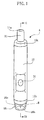
- the body fluid sampler A which is a portable medical instrument used for the self-sampling of blood for example, holds a lancet B for allowing its instantaneous upward and downward movement.
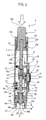
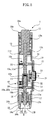
- the body fluid sampler A comprises a main case 10, a piston 11, a first and a second plunger rods 12, 15, a first through a third springs 13, 14, 17, a lancet mount 16, a cap 18, a first and a second latch mechanisms 20, 26, a release mechanism 30 and a vacuum relief mechanism 40 and soon.
- the lancet B comprises a columnar solid body B2 integrally formed with a pointed tip B1 in the form of a needle tip.
- the main case 10 which comprises a hollow cylinder of a portable size, has an upper end to which a head cover 10a is attached.
- the head cover 10a is formed with an upper end opening 10A for inserting the piston 11.
- the main case 10 has a lower end to which a lower cover 10b is attached.
- the lower cover 10b is formed with a lower end opening 10B for allowing vertical movement of the lancet B.
- the main case 10 defines a case chamber 10c which communicates, through the lower end opening 10B of the lower cover 10b, with the internal space of the cap 18 attached to the lower end of the lower cover 10b.
- the piston 11 has an upper end 11a projecting from the head cover 10a through the upper end opening 10A.
- the piston 11 has a bottom portion 11b inserted in the case chamber 10c.
- the upper end 11a of the piston 11 is depressed by the user's finger or thumb for example.
- the bottom portion 11b of the piston 11 has an outer diameter which coincides with the inner diameter of the case chamber 10c.
- the bottom portion 11b of the piston 11 is formed, at the outer circumferential surface thereof, with an O-ring 11d which closely contacts the inner wall of the case chamber 10c for airtight sealing. With this arrangement, the piston 11 is airtightly movable up and down in the case chamber 10c.
- the first plunger rod 12 is integral with the piston 11 and projects downward from the bottom portion 11b of the piston 11.
- the first plunger rod 12 is formed, at a longitudinally intermediate position thereof, with an engagement portion 12a which is tapered to provide a radially extending flat bottom surface.
- the first plunger rod 12 has a lower end integrally formed with a spring holder 12b.
- the spring holder 12b comprises a generally hollow cylinder for holding the spring 14 therein.
- the first spring 13 has an upper end 13a fixed to the main case 10 and a lower end 13b fixed to the piston 11. As the piston 11 moves downward, the first spring 13 works to pull back the piston 11 upward by its elastic restoring force. Specifically, when the first spring 13, which is normally held in a state shown in Fig. 2, is tensioned, it elastically pulls back the piston 11 upwardly.
- the second spring 14 has an upper end fixed to the spring holder 12b and a lower end fixed to the upper end of the second plunger rod 15.
- the second spring 14 works to elastically push back the first and the second plunger rods 12, 15 upward and downward, respectively. Specifically, when the second spring 14 is compressed from its normal state shown in Fig. 2 by the first and the second plunger rods 12, 15, it works to elastically push back these rods.
- the second plunger rod 15 is connected, via the second spring 14, to a lower portion of the first plunger rod 12.
- the second plunger rod 15 is formed, at a longitudinally intermediate position thereof, with an engagement portion 15a which is tapered to provide a radially extending flat upper surface.
- the lancet B is mounted to and held by the lancet mount 16.
- the lancet mount 16 is held by a third spring 17 in facing relationship to the lower end 15b of the second plunger rod 15 with a predetermined spacing therefrom.
- the lancet mount 16 is movable up and down in accordance with the elastic deformation of the third spring 17. It is to be noted that the lancet B is removable from the lancet mount 16 with the pointed tip B1 oriented downward.
- the third spring 17 has an upper end 17a fixed to the lancet mount 16 and a lower end 17b fixed to the inner side of the lower cover 10b.
- the third spring 17 works to elastically force the lancet mount 16 upward for recovery to its normal position.
- the third spring 17 is compressed from its normal state shown in Fig. 2, it elastically pushes back the lancet mount 16 upward.
- the cap 18 may be entirely formed of a transparent plastic material for example.
- the cap 18 is formed, at the end thereof, with an opening 18b.
- the cap 18 is fitted outwardly to the lower cover 10b of the main case 10.
- the cap 18 has an accommodation space 18a for accommodating the pointed tip B1 of the lancet B projecting through the lower opening 10B of the under cover 10. In sampling blood, the end of the cap 18 is pressed against the skin of the user to close the opening 18b.
- the cap 18 is provided with an O-ring 18c for providing airtightness of the accommodation space 18a. Therefore, by closing the opening 18b with the skin, air is trapped in the accommodation space 18a through the case chamber 10c.
- the cap 18 is fitted over the lower cover 10b via threads (not shown) formed at the inner circumferential surface of the cap 18. The distance H from the opening 18b to the pointed tip B1 of the lancet B can be adjusted by varying the extent of screwing the cap 18.
- the first latch mechanism 20 includes a first engagement member 21 having a stopper 21a corresponding to the engagement portion 12a of the first plunger rod 12, and a latch spring 22 for biasing the stopper 21a radially toward the first plunger rod 12.
- the first engagement member 21 is held as pressed against the outer circumferential surface of the first plunger rod 12.
- the latch spring 22 is provided at a predetermined position on the inner circumferential surface of the main case 10.
- the second latch mechanism 26 includes a second engagement member 27 having a stopper 27a corresponding to the engagement portion 15a of the second plunger rod 15, and a latch spring 28 for biasing the stopper 27a radially toward the second plunger rod 15.
- the second engagement member 27 is held as pressed against the outer circumferential surface of the second plunger rod 15.
- the latch spring 28 is provided at a predetermined position on the inner circumferential surface of the main case 10.
- the release mechanism 40 releases the first and the second plunger rods 12, 15 from the state restricted by the first and the second latch mechanisms 20, 26, respectively.
- the release mechanism 40 includes a release button 31 engaging the first and the second engagement members 21, 27 at positions opposite to the latch springs 22, 28, respectively, for simultaneously biasing these radially outward, a support member 32 for supporting the release button 31 within the case chamber 10c, and a shield member 33 interposed for keeping the airtightness between the release button 31 and the case chamber 10c.
- the release button 31 includes a push portion 31a projecting from a predetermined portion of the side surface of the main case 10.
- the shield member 33 comprises a film formed of a rubber for example.
- the vacuum relief mechanism 50 serves to release the vacuum condition in the case chamber 10c after pushing the release button 31.
- the vacuum relief mechanism 50 comprises a vacuum relief button 41 having a push portion 41a projecting through a port 10d provided at the side surface of the main case 10, a vacuum relief spring 42 for elastically biasing a flange portion 41b of the vacuum relief button 41 in facing relationship to the port 10d, and a nut 43 for holding the vacuum relief spring 42 within the case chamber 10c.
- the user performs a first operation. Specifically, the user pushes the upper end 11a of the piston 11 with the thumb for example to push down the piston 11. At this time, the user need not bring the opening 18b of the cap 18 into pressing contact with the skin. As a result, the piston 11 together with the first plunger rod 12 moves downward against the elastic restoring force of the first spring 13. Further, the second spring 14 and the second plunger rod 15 move downward accompanying the first plunger rod 12. In this case, the volume in the case chamber 10c gradually decreases as the bottom portion 11b of the piston 11 moves downward.
- the engagement portion 15a of the second plunger rod 15 first engages the stopper 27a, and the engagement portion 12a of the first plunger rod 12 then engages the stopper 21a.
- the distance between the vertically spaced two engagement portions 12a, 15a is set larger than the distance between the stoppers 21a and 27a of the first and the second engagement members 21, 27.
- a preliminary operation before launching the lancet B is completed in the above-described manner.
- the release button 31 slightly projects outward.
- the first spring 13 is tensioned approximately to its maximum length, and the volume in the case chamber 10c is kept minimum because the bottom portion 11b of the piston 11 has moved to the lowest limit position.
- Fig. 6 illustrates the state immediately after the release button 31 is pushed.
- the first and the second plunger rods 12, 15 which have been restricted by the first and the second engagement members 21, 27 are simultaneously released from the respective stoppers 21a, 27a.
- the first and the second plunger rods 12, 15 quickly move upward and downward, respectively, in a mutually repelling manner due to the elastic restoring force of the second spring 14.
- the second plunger rod 15 strongly hits or pushes the lancet mount 16 downward. Therefore, the pointed tip B1 of the lancet B integrally provided on the lancet mount 16 moves toward the opening 18b to instantaneously stab the skin S. Then, the pointed tip B1 of the lancet B is removed from the skin S due to the elastic restoring force of the third spring 17.
- the first plunger rod 12 is pulled back and held at a position close to the initial position together with the piston 11 pulled back upward due to the elastic restoring force of the first spring 13.
- the opening 18b of the cap 18 of the case chamber 10c is closed with the skin S. Therefore, as the piston 11 moves upward, the volume of the case chamber 10c gradually increases.
- the pressure in the case chamber 10c is reduced to a subatmospheric pressure so that the pressure in the accommodation space 18a of the cap 18, which communicates with the case chamber 10c, is also reduced. Since the shield member 33 is provided at the clearance between the release button 31 and the case chamber 10c, the case chamber 10c is prevented from air leakage relative to the outside. Therefore, the skin S closing the opening 18b of the cap 18 bulges due to the suction of the vacuum. As a result, bleeding is accelerated from the portion stabbed by the pointed tip B1 of the lancet B. The bleeding state can be observed by the user through the transparent cap 18.
- the vacuum relief button 41 of the vacuum relief mechanism 50 is pushed by the user, as shown in Figs. 7 and 8.
- air is introduced from the outside through the port 10d formed in the main case 10 and a hole 43a of the nut 43 into the case chamber 10c.
- the pressure in the case chamber 10c returns to the initial atmospheric pressure.
- the pressure in the accommodation space 18a communicating with the case chamber 10c returns to the atmospheric pressure. Therefore, the skin S closing the opening 18b of the cap 18 is relieved from the vacuum sucked state. Therefore, the opening 18b of the cap 18 can be easily removed from the skin S.
- the preparation for launching the lancet B can be completed by one-push operation. Further, the subsequent launching of the lancet B can be completed just by once pushing the release button 31.
- the first operation of pushing down the piston 11 can be performed under the atmospheric pressure. Therefore, the user needs only to push down the piston 11 by a predetermined stroke without using a strong force. Thus, the user can operate the apparatus easily without anxiety.
- the vacuum state of the case chamber 10c is relieved by pushing the vacuum relief button 41.
- the vacuum relief button 41 is provided separately from the release button 31 for launching the lancet B, which decreases the possibility of erroneously launching the lancet B. Therefore, the user can handle the apparatus safely.
- the present invention is not limited to the above-described embodiment.
- coiled springs are utilized for launching the lancet B and for reducing the pressure in the case chamber 10c, any other elastic members may be used if only they can be elastically compressed and restored sufficiently.
- the body fluid sampler A is preferably used for self-sampling blood
- the apparatus may be used for sampling body fluid other than blood, which can be sampled through the skin.
Landscapes
- Health & Medical Sciences (AREA)
- Life Sciences & Earth Sciences (AREA)
- Engineering & Computer Science (AREA)
- Molecular Biology (AREA)
- Animal Behavior & Ethology (AREA)
- Pathology (AREA)
- Physics & Mathematics (AREA)
- Biomedical Technology (AREA)
- Heart & Thoracic Surgery (AREA)
- Medical Informatics (AREA)
- Hematology (AREA)
- Surgery (AREA)
- Biophysics (AREA)
- General Health & Medical Sciences (AREA)
- Public Health (AREA)
- Veterinary Medicine (AREA)
- Dermatology (AREA)
- Manufacturing & Machinery (AREA)
- Pain & Pain Management (AREA)
- Measurement Of The Respiration, Hearing Ability, Form, And Blood Characteristics Of Living Organisms (AREA)
Abstract
Description
Claims (6)
- A body fluid sampler comprising:a cylindrical main case having a first end provided with a first opening and a second end provided with a second opening;a piston inserted in the main case to project from the first opening for movement within the main case airtightly with respect to an inner wall of the main case;a first plunger rod extending integrally from the piston toward said second end;a first elastic member for elastically urging the piston toward said first end;a second plunger rod extending from the first plunger rod toward said second end for movement within the main case with a compressible second elastic member interposed between the first plunger rod and the second plunger rod;a lancet mount associated with the second plunger rod adjacent to said second end for movement within the main case, the lancet mount being provided with a lancet oriented toward said second end;a third elastic member for elastically urging the lancet mount toward said first end;a latch mechanism which works, when the piston is pushed down for movement toward said second end together with the first plunger rod, for restricting movement of the second plunger rod toward said second end against a pushing force of the second elastic member and for restricting rebounding of the piston and first plunger rod which have been moved toward said second end while allowing the second elastic member to be compressed; anda release mechanism for releasing the first plunger rod and second plunger rod which have been latched by the latch mechanism.
- The body fluid sampler according to claim 1, wherein the latch mechanism includes:a first and a second engagement members each of which has a stopper for stopping a corresponding one of the first and the second plunger rods;a latching elastic member for elastically biasing each of the engagement members toward the corresponding one of the first and the second plunger rods; andengagement portions respectively formed on the first and the second plunger rods, the engagement portions being spaced from each other by a distance which is larger than a distance between the stoppers when the plunger rods are held in an initial state;the release mechanism including:a release button for simultaneously releasing the stoppers from the corresponding engagement portions against an elastic biasing force of the latching elastic member.
- The body fluid sampler according to claim 2, wherein the release button is provided with a push portion projecting from a predetermined portion of a side surface of the main case while keeping airtightness relative to the main case.
- The body fluid sampler according to claim 1, wherein the main case is provided with a vacuum relief mechanism for relieving a vacuum state within the main case generated by pulling back the piston toward said first end.
- The body fluid sampler according to claim 4, wherein the vacuum relief mechanism is provided with a vacuum relief button partially projecting from a predetermined portion of a side surface of the main case, the vacuum relief button being elastically urged in the projecting direction while keeping airtightness of the main case, the vacuum relief button being pushed against the elastic urging force for allowing air passage between inside and outside of the main case.
- The body fluid sampler according to claim 1, wherein the piston has an outer circumferential wall provided with an 0-ring for closely contacting the inner wall of the main case.
Applications Claiming Priority (3)
| Application Number | Priority Date | Filing Date | Title |
|---|---|---|---|
| JP27645199 | 1999-09-29 | ||
| JP27645199A JP4359671B2 (en) | 1999-09-29 | 1999-09-29 | Body fluid collection tool |
| PCT/JP2000/006745 WO2001022882A1 (en) | 1999-09-29 | 2000-09-28 | Body fluid sampling apparatus |
Publications (3)
| Publication Number | Publication Date |
|---|---|
| EP1219242A1 true EP1219242A1 (en) | 2002-07-03 |
| EP1219242A4 EP1219242A4 (en) | 2005-04-06 |
| EP1219242B1 EP1219242B1 (en) | 2009-04-08 |
Family
ID=17569628
Family Applications (1)
| Application Number | Title | Priority Date | Filing Date |
|---|---|---|---|
| EP00962959A Expired - Lifetime EP1219242B1 (en) | 1999-09-29 | 2000-09-28 | Body fluid sampling apparatus |
Country Status (5)
| Country | Link |
|---|---|
| US (1) | US6730046B1 (en) |
| EP (1) | EP1219242B1 (en) |
| JP (1) | JP4359671B2 (en) |
| DE (1) | DE60041975D1 (en) |
| WO (1) | WO2001022882A1 (en) |
Cited By (10)
| Publication number | Priority date | Publication date | Assignee | Title |
|---|---|---|---|---|
| WO2005013823A1 (en) * | 2003-08-06 | 2005-02-17 | Htl Strefa Spolka Z O.O. | Skin puncturing device |
| WO2005107595A1 (en) * | 2004-05-05 | 2005-11-17 | Becton Dickinson And Company | Squeeze-activated medical puncturing device |
| EP2425777A1 (en) * | 2005-04-07 | 2012-03-07 | Becton, Dickinson and Company | Lancet device |
| WO2011090813A3 (en) * | 2010-01-19 | 2012-04-12 | Jacobs Christopher A | Vacuum assisted lancing system and method for blood extraction with minimal pain |
| CN102481125A (en) * | 2009-09-10 | 2012-05-30 | 尼普洛株式会社 | Disposable Blood Collection Set |
| WO2013155052A1 (en) * | 2012-04-09 | 2013-10-17 | Facet Technologies, Llc | Push-to-charge lancing device |
| US8657763B2 (en) | 2010-01-19 | 2014-02-25 | Christopher A. Jacobs | Vacuum assisted lancing system with elective vacuum release and method for blood extraction with minimal pain |
| AU2014202573B2 (en) * | 2005-04-07 | 2016-02-25 | Becton, Dickinson And Company | Lancet device |
| EP3111844A1 (en) * | 2015-07-02 | 2017-01-04 | Joinsoon Medical Technology Co., Ltd. | High speed lancing device with lancet ejection assembly |
| CN108903953A (en) * | 2014-05-21 | 2018-11-30 | 广州市银睿投资咨询有限公司 | A kind of safety type blood collecting needle construction |
Families Citing this family (34)
| Publication number | Priority date | Publication date | Assignee | Title |
|---|---|---|---|---|
| US7235056B2 (en) | 1996-05-17 | 2007-06-26 | Amira Medical | Body fluid sampling device and methods of use |
| EP1579814A3 (en) | 1996-05-17 | 2006-06-14 | Roche Diagnostics Operations, Inc. | Methods and apparatus for sampling and analyzing body fluid |
| US7828749B2 (en) | 1996-05-17 | 2010-11-09 | Roche Diagnostics Operations, Inc. | Blood and interstitial fluid sampling device |
| US20020010406A1 (en) | 1996-05-17 | 2002-01-24 | Douglas Joel S. | Methods and apparatus for expressing body fluid from an incision |
| US6558402B1 (en) | 1999-08-03 | 2003-05-06 | Becton, Dickinson And Company | Lancer |
| US20020188223A1 (en) | 2001-06-08 | 2002-12-12 | Edward Perez | Devices and methods for the expression of bodily fluids from an incision |
| EP1432353A1 (en) * | 2001-09-26 | 2004-06-30 | Hoffman-La Roche AG | Method and apparatus for sampling bodily fluid |
| CN101152089B (en) * | 2002-11-15 | 2012-04-25 | 爱科来株式会社 | Lancet and needle insertion device |
| US7288102B2 (en) * | 2003-03-20 | 2007-10-30 | Facet Technologies, Llc | Lancing device with decoupled lancet |
| US7494498B2 (en) | 2003-03-24 | 2009-02-24 | Facet Technologies, Llc | Lancing device with floating lancet |
| US20040254599A1 (en) * | 2003-03-25 | 2004-12-16 | Lipoma Michael V. | Method and apparatus for pre-lancing stimulation of puncture site |
| TW200518717A (en) * | 2003-10-15 | 2005-06-16 | Surgilance Pte Ltd | Lancet assembly |
| US20050125019A1 (en) * | 2003-12-05 | 2005-06-09 | Paul Kudrna | Lancet device and method |
| US20050125017A1 (en) * | 2003-12-05 | 2005-06-09 | Paul Kudrna | Lancet device and method |
| US7293803B2 (en) * | 2003-12-16 | 2007-11-13 | Ching-Nan Chu | Method for indicating the user's name on a blood-sampling needle pen and the product thereof |
| FR2869533B1 (en) * | 2004-05-03 | 2006-07-28 | Sedat Sa | SYRINGE FOR MEDICAL INTERVENTIONS AND NECESSARY FOR RECONSTITUTION OF EXTEMPORANEOUS SUBSTANCES COMPRISING SUCH A SYRINGE |
| USD560798S1 (en) * | 2005-03-29 | 2008-01-29 | Enomoto Co., Ltd. | Blood collecting device |
| US20060247671A1 (en) * | 2005-05-02 | 2006-11-02 | Levaughn Richard W | Compact, multi-use micro-sampling device |
| US8043318B2 (en) * | 2007-02-08 | 2011-10-25 | Stat Medical Devices, Inc. | Push-button lance device and method |
| KR100912202B1 (en) * | 2008-07-03 | 2009-08-14 | (주)보성메디텍 | Lancet integrated cap and painless blood collector |
| JP5121940B2 (en) * | 2008-12-09 | 2013-01-16 | パナソニック株式会社 | Depressurization mechanism, puncture device, blood analyzer, and sensor mounting mechanism |
| KR100971171B1 (en) * | 2009-12-14 | 2010-07-20 | 홍관호 | A safty lancet for anti reuse |
| DE102011056626B4 (en) * | 2011-12-19 | 2014-02-13 | Gerresheimer Regensburg Gmbh | Lancing device for blood sampling |
| DE102012019400A1 (en) * | 2012-10-04 | 2014-04-10 | Gerresheimer Regensburg Gmbh | Lancing device for blood sampling |
| USD729379S1 (en) * | 2013-09-10 | 2015-05-12 | Theranos, Inc. | Blood collection device |
| USD762298S1 (en) | 2013-09-10 | 2016-07-26 | Theranos, Inc. | Blood collection device |
| CA3028349A1 (en) * | 2016-05-02 | 2017-11-09 | Lim Chel Choi | Disposable painless lancet and lancing device for use therewith |
| US20190275261A1 (en) * | 2017-01-12 | 2019-09-12 | SPIRATION, INC., d/b/a OLYMPUS RESPIRATORY AMERICA | Safety locked needle |
| US10610215B2 (en) * | 2017-07-11 | 2020-04-07 | Durastat Llc | Devices and methods for suture placement |
| CN107582387A (en) * | 2017-08-29 | 2018-01-16 | 丁允志 | A kind of electronic bloodletting device |
| CN112932484A (en) * | 2021-03-23 | 2021-06-11 | 起源细胞技术(滁州)有限公司 | Integrative plug of vacuum test tube |
| CN113243938B (en) * | 2021-05-13 | 2022-05-17 | 高美龄 | Plunger valve type filtering medical suction nozzle head |
| CN113729878B (en) * | 2021-08-18 | 2022-04-08 | 真健康(北京)医疗科技有限公司 | Quick release puncture needle guide and puncture assembly |
| CN115721308B (en) * | 2022-12-20 | 2024-12-31 | 苏州思迈德生物科技有限公司 | Blood sampling device for peripheral blood of capillary vessel |
Family Cites Families (8)
| Publication number | Priority date | Publication date | Assignee | Title |
|---|---|---|---|---|
| JPH0595937A (en) | 1991-07-09 | 1993-04-20 | Meitec Corp | Blood sampler |
| JP2630197B2 (en) | 1993-04-28 | 1997-07-16 | 株式会社ニッショー | Blood suction device |
| US5350392A (en) * | 1994-02-03 | 1994-09-27 | Miles Inc. | Lancing device with automatic cocking |
| JP2723048B2 (en) * | 1994-06-24 | 1998-03-09 | 株式会社ニッショー | Blood suction device |
| US5873887A (en) | 1996-10-25 | 1999-02-23 | Bayer Corporation | Blood sampling device |
| US5916230A (en) * | 1997-06-16 | 1999-06-29 | Bayer Corporation | Blood sampling device with adjustable end cap |
| US5964718A (en) * | 1997-11-21 | 1999-10-12 | Mercury Diagnostics, Inc. | Body fluid sampling device |
| US6086545A (en) * | 1998-04-28 | 2000-07-11 | Amira Medical | Methods and apparatus for suctioning and pumping body fluid from an incision |
-
1999
- 1999-09-29 JP JP27645199A patent/JP4359671B2/en not_active Expired - Fee Related
-
2000
- 2000-09-28 EP EP00962959A patent/EP1219242B1/en not_active Expired - Lifetime
- 2000-09-28 WO PCT/JP2000/006745 patent/WO2001022882A1/en not_active Ceased
- 2000-09-28 DE DE60041975T patent/DE60041975D1/en not_active Expired - Lifetime
- 2000-09-28 US US10/089,296 patent/US6730046B1/en not_active Expired - Fee Related
Cited By (27)
| Publication number | Priority date | Publication date | Assignee | Title |
|---|---|---|---|---|
| GB2420287A (en) * | 2003-08-06 | 2006-05-24 | Htl Strefa Spolka Z O O | Skin puncturing device |
| GB2420287B (en) * | 2003-08-06 | 2007-03-28 | Htl Strefa Spolka Z O O | Skin puncturing device |
| WO2005013823A1 (en) * | 2003-08-06 | 2005-02-17 | Htl Strefa Spolka Z O.O. | Skin puncturing device |
| US8449479B2 (en) | 2004-05-05 | 2013-05-28 | Becton, Dickinson And Company | Squeeze activated medical puncturing device |
| WO2005107595A1 (en) * | 2004-05-05 | 2005-11-17 | Becton Dickinson And Company | Squeeze-activated medical puncturing device |
| AU2005240071B2 (en) * | 2004-05-05 | 2011-04-07 | Becton, Dickinson And Company, | Squeeze-activated medical puncturing device |
| CN1964667B (en) * | 2004-05-05 | 2013-11-06 | 贝克顿·迪金森公司 | Squeeze-activated medical puncturing device |
| US10849534B2 (en) | 2005-04-07 | 2020-12-01 | Becton, Dickinson And Company | Lancet device |
| US9993184B2 (en) | 2005-04-07 | 2018-06-12 | Becton, Dickinson And Company | Lancet device |
| AU2014202573B2 (en) * | 2005-04-07 | 2016-02-25 | Becton, Dickinson And Company | Lancet device |
| EP2425777A1 (en) * | 2005-04-07 | 2012-03-07 | Becton, Dickinson and Company | Lancet device |
| EP2476374A4 (en) * | 2009-09-10 | 2013-02-13 | Nipro Corp | Disposable blood collecting instrument |
| CN102481125A (en) * | 2009-09-10 | 2012-05-30 | 尼普洛株式会社 | Disposable Blood Collection Set |
| US8460210B2 (en) | 2010-01-19 | 2013-06-11 | Christopher A. Jacobs | Vacuum assisted lancing system with controlled rate and method for blood extraction with minimal pain |
| US8460211B2 (en) | 2010-01-19 | 2013-06-11 | Christopher A. Jacobs | Vacuum assisted lancing system with bidirectional mechanism and method for blood extraction with minimal pain |
| US8485991B2 (en) | 2010-01-19 | 2013-07-16 | Christopher A. Jacobs | Vacuum assisted lancing system with system and method for blood extraction and masking pain |
| WO2011090813A3 (en) * | 2010-01-19 | 2012-04-12 | Jacobs Christopher A | Vacuum assisted lancing system and method for blood extraction with minimal pain |
| US8480596B2 (en) | 2010-01-19 | 2013-07-09 | Christopher A. Jacobs | Vacuum assisted lancing system and method for blood extraction with minimal pain |
| US8657763B2 (en) | 2010-01-19 | 2014-02-25 | Christopher A. Jacobs | Vacuum assisted lancing system with elective vacuum release and method for blood extraction with minimal pain |
| CN102802524B (en) * | 2010-01-19 | 2015-01-28 | 克里斯托弗.A.雅各布斯 | Vacuum-assisted puncture system and method for drawing blood with minimal pain |
| US8485990B2 (en) | 2010-01-19 | 2013-07-16 | Christopher A. Jacobs | Vacuum assisted lancing system with depth controller and method for blood extraction with minimal pain |
| CN102802524A (en) * | 2010-01-19 | 2012-11-28 | 克里斯托弗.A.雅各布斯 | Vacuum-assisted puncture system and method for drawing blood with minimal pain |
| US9622695B2 (en) | 2010-01-19 | 2017-04-18 | Christopher A. Jacobs | Vacuum assisted lancing system and method for blood extraction with minimal pain |
| US9770201B2 (en) | 2010-01-19 | 2017-09-26 | Christopher A. Jacobs | Vacuum assisted lancing system with elective vacuum release and method for blood extraction with minimal pain |
| WO2013155052A1 (en) * | 2012-04-09 | 2013-10-17 | Facet Technologies, Llc | Push-to-charge lancing device |
| CN108903953A (en) * | 2014-05-21 | 2018-11-30 | 广州市银睿投资咨询有限公司 | A kind of safety type blood collecting needle construction |
| EP3111844A1 (en) * | 2015-07-02 | 2017-01-04 | Joinsoon Medical Technology Co., Ltd. | High speed lancing device with lancet ejection assembly |
Also Published As
| Publication number | Publication date |
|---|---|
| JP4359671B2 (en) | 2009-11-04 |
| US6730046B1 (en) | 2004-05-04 |
| EP1219242B1 (en) | 2009-04-08 |
| WO2001022882A1 (en) | 2001-04-05 |
| DE60041975D1 (en) | 2009-05-20 |
| JP2001095787A (en) | 2001-04-10 |
| EP1219242A4 (en) | 2005-04-06 |
Similar Documents
| Publication | Publication Date | Title |
|---|---|---|
| EP1219242B1 (en) | Body fluid sampling apparatus | |
| JP2723048B2 (en) | Blood suction device | |
| CN102245104B (en) | Pressure reduction mechanism, puncture device and blood analysis device | |
| EP0622046B1 (en) | Suction-type blood sampler | |
| US5518006A (en) | Blood sampling device | |
| US4883068A (en) | Blood sampling device and method | |
| US4261358A (en) | Automatic syringe plunger | |
| CN101203177B (en) | Blood taking needle device | |
| US20040015064A1 (en) | Blood sampling apparatus | |
| RU2343831C2 (en) | Skin incision lancet device, method of incised area opening | |
| CN100405975C (en) | Piercing device with trigger mechanism to control the piercing depth | |
| JP3631790B2 (en) | Puncture device with automatic preparation function | |
| EP0519982B1 (en) | Single use automated aspiration biopsy device | |
| US20030088191A1 (en) | Blood sampling device with diaphragm actuated lancet | |
| US20110319919A1 (en) | Cocking mechanism for lancing device | |
| JPH07213925A (en) | Fixed volume blood sampling tool | |
| EP2381847B1 (en) | Skin pricking device | |
| JP3304342B2 (en) | Blood suction device | |
| JP2000225110A (en) | Stabbing tool | |
| JP3223496B2 (en) | Blood suction device | |
| US20250303134A1 (en) | Valve assembly | |
| JPH06327655A (en) | Apparatus for drawing blood | |
| JP2009022516A (en) | Puncture tool, biosensor cartridge, suction puncture device, and biosensor measurement device |
Legal Events
| Date | Code | Title | Description |
|---|---|---|---|
| PUAI | Public reference made under article 153(3) epc to a published international application that has entered the european phase |
Free format text: ORIGINAL CODE: 0009012 |
|
| 17P | Request for examination filed |
Effective date: 20020418 |
|
| AK | Designated contracting states |
Kind code of ref document: A1 Designated state(s): AT BE CH CY DE DK ES FI FR GB GR IE IT LI LU MC NL PT SE |
|
| RIN1 | Information on inventor provided before grant (corrected) |
Inventor name: MURAKAMI, ATSUSHI, ARKRAY, INC. Inventor name: HYODO, HIROSHI, ARKRAY, INC. Inventor name: HAMAMOTO, KATSUMI, . |
|
| RBV | Designated contracting states (corrected) |
Designated state(s): AT BE CH CY DE FR GB IT LI |
|
| A4 | Supplementary search report drawn up and despatched |
Effective date: 20050217 |
|
| GRAP | Despatch of communication of intention to grant a patent |
Free format text: ORIGINAL CODE: EPIDOSNIGR1 |
|
| RBV | Designated contracting states (corrected) |
Designated state(s): DE FR GB IT |
|
| GRAS | Grant fee paid |
Free format text: ORIGINAL CODE: EPIDOSNIGR3 |
|
| GRAA | (expected) grant |
Free format text: ORIGINAL CODE: 0009210 |
|
| AK | Designated contracting states |
Kind code of ref document: B1 Designated state(s): DE FR GB IT |
|
| REG | Reference to a national code |
Ref country code: GB Ref legal event code: FG4D |
|
| REF | Corresponds to: |
Ref document number: 60041975 Country of ref document: DE Date of ref document: 20090520 Kind code of ref document: P |
|
| PLBE | No opposition filed within time limit |
Free format text: ORIGINAL CODE: 0009261 |
|
| STAA | Information on the status of an ep patent application or granted ep patent |
Free format text: STATUS: NO OPPOSITION FILED WITHIN TIME LIMIT |
|
| 26N | No opposition filed |
Effective date: 20100111 |
|
| PGFP | Annual fee paid to national office [announced via postgrant information from national office to epo] |
Ref country code: IT Payment date: 20100924 Year of fee payment: 11 Ref country code: FR Payment date: 20101005 Year of fee payment: 11 |
|
| PGFP | Annual fee paid to national office [announced via postgrant information from national office to epo] |
Ref country code: GB Payment date: 20100921 Year of fee payment: 11 |
|
| PGFP | Annual fee paid to national office [announced via postgrant information from national office to epo] |
Ref country code: DE Payment date: 20100922 Year of fee payment: 11 |
|
| GBPC | Gb: european patent ceased through non-payment of renewal fee |
Effective date: 20110928 |
|
| PG25 | Lapsed in a contracting state [announced via postgrant information from national office to epo] |
Ref country code: IT Free format text: LAPSE BECAUSE OF NON-PAYMENT OF DUE FEES Effective date: 20110928 |
|
| REG | Reference to a national code |
Ref country code: FR Ref legal event code: ST Effective date: 20120531 |
|
| REG | Reference to a national code |
Ref country code: DE Ref legal event code: R119 Ref document number: 60041975 Country of ref document: DE Effective date: 20120403 |
|
| PG25 | Lapsed in a contracting state [announced via postgrant information from national office to epo] |
Ref country code: DE Free format text: LAPSE BECAUSE OF NON-PAYMENT OF DUE FEES Effective date: 20120403 |
|
| PG25 | Lapsed in a contracting state [announced via postgrant information from national office to epo] |
Ref country code: FR Free format text: LAPSE BECAUSE OF NON-PAYMENT OF DUE FEES Effective date: 20110930 Ref country code: GB Free format text: LAPSE BECAUSE OF NON-PAYMENT OF DUE FEES Effective date: 20110928 |