EP1218552B1 - Low-carbon steels of superior mechanical and corrosion properties - Google Patents
Low-carbon steels of superior mechanical and corrosion properties Download PDFInfo
- Publication number
- EP1218552B1 EP1218552B1 EP00918462A EP00918462A EP1218552B1 EP 1218552 B1 EP1218552 B1 EP 1218552B1 EP 00918462 A EP00918462 A EP 00918462A EP 00918462 A EP00918462 A EP 00918462A EP 1218552 B1 EP1218552 B1 EP 1218552B1
- Authority
- EP
- European Patent Office
- Prior art keywords
- weight
- alloy composition
- accordance
- martensite
- microstructure
- Prior art date
- Legal status (The legal status is an assumption and is not a legal conclusion. Google has not performed a legal analysis and makes no representation as to the accuracy of the status listed.)
- Expired - Lifetime
Links
- 238000005260 corrosion Methods 0.000 title claims abstract description 14
- 230000007797 corrosion Effects 0.000 title claims abstract description 14
- 229910000975 Carbon steel Inorganic materials 0.000 title claims description 4
- 229910045601 alloy Inorganic materials 0.000 claims abstract description 63
- 239000000956 alloy Substances 0.000 claims abstract description 63
- 239000000203 mixture Substances 0.000 claims abstract description 41
- 238000001816 cooling Methods 0.000 claims abstract description 37
- 229910000734 martensite Inorganic materials 0.000 claims abstract description 36
- 229910001566 austenite Inorganic materials 0.000 claims abstract description 34
- 150000001247 metal acetylides Chemical class 0.000 claims abstract description 21
- 150000004767 nitrides Chemical class 0.000 claims abstract description 17
- 230000007704 transition Effects 0.000 claims abstract description 16
- 230000000717 retained effect Effects 0.000 claims abstract description 15
- 238000000034 method Methods 0.000 claims description 33
- 239000011651 chromium Substances 0.000 claims description 29
- OKTJSMMVPCPJKN-UHFFFAOYSA-N Carbon Chemical compound [C] OKTJSMMVPCPJKN-UHFFFAOYSA-N 0.000 claims description 28
- VYZAMTAEIAYCRO-UHFFFAOYSA-N Chromium Chemical compound [Cr] VYZAMTAEIAYCRO-UHFFFAOYSA-N 0.000 claims description 28
- 229910052799 carbon Inorganic materials 0.000 claims description 28
- 229910052804 chromium Inorganic materials 0.000 claims description 28
- 238000005275 alloying Methods 0.000 claims description 27
- 230000008569 process Effects 0.000 claims description 27
- 229910052710 silicon Inorganic materials 0.000 claims description 17
- XUIMIQQOPSSXEZ-UHFFFAOYSA-N Silicon Chemical compound [Si] XUIMIQQOPSSXEZ-UHFFFAOYSA-N 0.000 claims description 16
- 239000010703 silicon Substances 0.000 claims description 16
- XEEYBQQBJWHFJM-UHFFFAOYSA-N Iron Chemical compound [Fe] XEEYBQQBJWHFJM-UHFFFAOYSA-N 0.000 claims description 11
- PWHULOQIROXLJO-UHFFFAOYSA-N Manganese Chemical compound [Mn] PWHULOQIROXLJO-UHFFFAOYSA-N 0.000 claims description 9
- 229910052748 manganese Inorganic materials 0.000 claims description 9
- 239000011572 manganese Substances 0.000 claims description 9
- IJGRMHOSHXDMSA-UHFFFAOYSA-N Atomic nitrogen Chemical compound N#N IJGRMHOSHXDMSA-UHFFFAOYSA-N 0.000 claims description 6
- 238000010791 quenching Methods 0.000 claims description 6
- XLYOFNOQVPJJNP-UHFFFAOYSA-N water Substances O XLYOFNOQVPJJNP-UHFFFAOYSA-N 0.000 claims description 6
- 229910052742 iron Inorganic materials 0.000 claims description 5
- 230000000171 quenching effect Effects 0.000 claims description 5
- 238000010438 heat treatment Methods 0.000 claims description 4
- 238000004519 manufacturing process Methods 0.000 claims description 4
- 239000010962 carbon steel Substances 0.000 claims description 3
- 229910052757 nitrogen Inorganic materials 0.000 claims description 3
- 229910000831 Steel Inorganic materials 0.000 abstract description 12
- 239000010959 steel Substances 0.000 abstract description 12
- 239000010409 thin film Substances 0.000 abstract description 7
- 239000010408 film Substances 0.000 abstract description 5
- 239000000047 product Substances 0.000 description 25
- 239000002244 precipitate Substances 0.000 description 11
- 229910000851 Alloy steel Inorganic materials 0.000 description 8
- 230000009466 transformation Effects 0.000 description 6
- 239000013078 crystal Substances 0.000 description 5
- WPBNNNQJVZRUHP-UHFFFAOYSA-L manganese(2+);methyl n-[[2-(methoxycarbonylcarbamothioylamino)phenyl]carbamothioyl]carbamate;n-[2-(sulfidocarbothioylamino)ethyl]carbamodithioate Chemical compound [Mn+2].[S-]C(=S)NCCNC([S-])=S.COC(=O)NC(=S)NC1=CC=CC=C1NC(=S)NC(=O)OC WPBNNNQJVZRUHP-UHFFFAOYSA-L 0.000 description 5
- 238000005096 rolling process Methods 0.000 description 5
- 230000015572 biosynthetic process Effects 0.000 description 4
- 229910001567 cementite Inorganic materials 0.000 description 3
- 238000010586 diagram Methods 0.000 description 3
- PXHVJJICTQNCMI-UHFFFAOYSA-N nickel Substances [Ni] PXHVJJICTQNCMI-UHFFFAOYSA-N 0.000 description 3
- 229910052782 aluminium Inorganic materials 0.000 description 2
- 229910001563 bainite Inorganic materials 0.000 description 2
- 238000005266 casting Methods 0.000 description 2
- 150000001875 compounds Chemical class 0.000 description 2
- KSOKAHYVTMZFBJ-UHFFFAOYSA-N iron;methane Chemical compound C.[Fe].[Fe].[Fe] KSOKAHYVTMZFBJ-UHFFFAOYSA-N 0.000 description 2
- 229910052759 nickel Inorganic materials 0.000 description 2
- 229910001562 pearlite Inorganic materials 0.000 description 2
- 238000010587 phase diagram Methods 0.000 description 2
- 230000009467 reduction Effects 0.000 description 2
- 229910000954 Medium-carbon steel Inorganic materials 0.000 description 1
- ZOKXTWBITQBERF-UHFFFAOYSA-N Molybdenum Chemical compound [Mo] ZOKXTWBITQBERF-UHFFFAOYSA-N 0.000 description 1
- XAGFODPZIPBFFR-UHFFFAOYSA-N aluminium Chemical compound [Al] XAGFODPZIPBFFR-UHFFFAOYSA-N 0.000 description 1
- 229910017052 cobalt Inorganic materials 0.000 description 1
- 239000010941 cobalt Substances 0.000 description 1
- GUTLYIVDDKVIGB-UHFFFAOYSA-N cobalt atom Chemical compound [Co] GUTLYIVDDKVIGB-UHFFFAOYSA-N 0.000 description 1
- 239000002131 composite material Substances 0.000 description 1
- 239000004567 concrete Substances 0.000 description 1
- 229910052802 copper Inorganic materials 0.000 description 1
- 238000009792 diffusion process Methods 0.000 description 1
- 230000002708 enhancing effect Effects 0.000 description 1
- 229910052751 metal Inorganic materials 0.000 description 1
- 239000002184 metal Substances 0.000 description 1
- 238000012986 modification Methods 0.000 description 1
- 230000004048 modification Effects 0.000 description 1
- 229910052750 molybdenum Inorganic materials 0.000 description 1
- 239000011733 molybdenum Substances 0.000 description 1
- 229910052758 niobium Inorganic materials 0.000 description 1
- 230000001376 precipitating effect Effects 0.000 description 1
- 238000001556 precipitation Methods 0.000 description 1
- 239000011150 reinforced concrete Substances 0.000 description 1
- 229920006395 saturated elastomer Polymers 0.000 description 1
- 239000000126 substance Substances 0.000 description 1
- 229910052719 titanium Inorganic materials 0.000 description 1
Images

Classifications
-
- C—CHEMISTRY; METALLURGY
- C21—METALLURGY OF IRON
- C21D—MODIFYING THE PHYSICAL STRUCTURE OF FERROUS METALS; GENERAL DEVICES FOR HEAT TREATMENT OF FERROUS OR NON-FERROUS METALS OR ALLOYS; MAKING METAL MALLEABLE, e.g. BY DECARBURISATION OR TEMPERING
- C21D6/00—Heat treatment of ferrous alloys
- C21D6/002—Heat treatment of ferrous alloys containing Cr
-
- C—CHEMISTRY; METALLURGY
- C21—METALLURGY OF IRON
- C21D—MODIFYING THE PHYSICAL STRUCTURE OF FERROUS METALS; GENERAL DEVICES FOR HEAT TREATMENT OF FERROUS OR NON-FERROUS METALS OR ALLOYS; MAKING METAL MALLEABLE, e.g. BY DECARBURISATION OR TEMPERING
- C21D1/00—General methods or devices for heat treatment, e.g. annealing, hardening, quenching or tempering
- C21D1/18—Hardening; Quenching with or without subsequent tempering
- C21D1/25—Hardening, combined with annealing between 300 degrees Celsius and 600 degrees Celsius, i.e. heat refining ("Vergüten")
-
- C—CHEMISTRY; METALLURGY
- C21—METALLURGY OF IRON
- C21D—MODIFYING THE PHYSICAL STRUCTURE OF FERROUS METALS; GENERAL DEVICES FOR HEAT TREATMENT OF FERROUS OR NON-FERROUS METALS OR ALLOYS; MAKING METAL MALLEABLE, e.g. BY DECARBURISATION OR TEMPERING
- C21D1/00—General methods or devices for heat treatment, e.g. annealing, hardening, quenching or tempering
- C21D1/18—Hardening; Quenching with or without subsequent tempering
-
- C—CHEMISTRY; METALLURGY
- C21—METALLURGY OF IRON
- C21D—MODIFYING THE PHYSICAL STRUCTURE OF FERROUS METALS; GENERAL DEVICES FOR HEAT TREATMENT OF FERROUS OR NON-FERROUS METALS OR ALLOYS; MAKING METAL MALLEABLE, e.g. BY DECARBURISATION OR TEMPERING
- C21D6/00—Heat treatment of ferrous alloys
- C21D6/008—Heat treatment of ferrous alloys containing Si
-
- C—CHEMISTRY; METALLURGY
- C21—METALLURGY OF IRON
- C21D—MODIFYING THE PHYSICAL STRUCTURE OF FERROUS METALS; GENERAL DEVICES FOR HEAT TREATMENT OF FERROUS OR NON-FERROUS METALS OR ALLOYS; MAKING METAL MALLEABLE, e.g. BY DECARBURISATION OR TEMPERING
- C21D7/00—Modifying the physical properties of iron or steel by deformation
- C21D7/02—Modifying the physical properties of iron or steel by deformation by cold working
-
- C—CHEMISTRY; METALLURGY
- C22—METALLURGY; FERROUS OR NON-FERROUS ALLOYS; TREATMENT OF ALLOYS OR NON-FERROUS METALS
- C22C—ALLOYS
- C22C38/00—Ferrous alloys, e.g. steel alloys
- C22C38/18—Ferrous alloys, e.g. steel alloys containing chromium
-
- C—CHEMISTRY; METALLURGY
- C22—METALLURGY; FERROUS OR NON-FERROUS ALLOYS; TREATMENT OF ALLOYS OR NON-FERROUS METALS
- C22C—ALLOYS
- C22C38/00—Ferrous alloys, e.g. steel alloys
- C22C38/18—Ferrous alloys, e.g. steel alloys containing chromium
- C22C38/34—Ferrous alloys, e.g. steel alloys containing chromium with more than 1.5% by weight of silicon
-
- C—CHEMISTRY; METALLURGY
- C21—METALLURGY OF IRON
- C21D—MODIFYING THE PHYSICAL STRUCTURE OF FERROUS METALS; GENERAL DEVICES FOR HEAT TREATMENT OF FERROUS OR NON-FERROUS METALS OR ALLOYS; MAKING METAL MALLEABLE, e.g. BY DECARBURISATION OR TEMPERING
- C21D2211/00—Microstructure comprising significant phases
- C21D2211/001—Austenite
-
- C—CHEMISTRY; METALLURGY
- C21—METALLURGY OF IRON
- C21D—MODIFYING THE PHYSICAL STRUCTURE OF FERROUS METALS; GENERAL DEVICES FOR HEAT TREATMENT OF FERROUS OR NON-FERROUS METALS OR ALLOYS; MAKING METAL MALLEABLE, e.g. BY DECARBURISATION OR TEMPERING
- C21D2211/00—Microstructure comprising significant phases
- C21D2211/008—Martensite
Definitions
- This invention resides in the field of steel alloys, particularly those of high strength, toughness, corrosion resistance, and cold formability, and also in the technology of the processing of steel alloys to form microstructures that provide the steel with particular physical and chemical properties.
- the microstructure plays a key role in establishing the properties of a particular steel alloy, and thus strength and toughness of the alloy depend not only on the selection and amounts of the alloying elements, but also on the crystalline phases present and their arrangement. Alloys intended for use in certain environments require higher strength and toughness, and in general a combination of properties that are often in conflict, since certain alloying elements that contribute to one property may detract from another.
- the alloys disclosed in the patents listed above are carbon steel alloys that have microstructures consisting of laths of martensite alternating with thin films of austenite and dispersed with fine grains of carbides produced by autotempering.
- the arrangement in which laths of one phase are separated by thin films of the other is referred to as a "dislocated lath" structure, and is formed by first heating the alloy into the austenite range, then cooling the alloy below a phase transition temperature into a range in which austenite transforms to martensite, accompanied by rolling to achieve the desired shape of the product and to refine the alternating lath and thin film arrangement.
- This microstructure is preferable to the alternative of a twinned martensite structure, since the lath structure has a greater toughness.
- the patents also disclose that excess carbon in the lath regions precipitates during the cooling process to form cementite (iron carbide, Fe 3 C) by a phenomenon known as "autotempering.” These autotempered carbides are believed to contribute to the toughness
- the dislocated lath structure produces a high-strength steel that is both tough and ductile, qualities that are needed for resistance to crack propagation and for sufficient formability to permit the successful fabrication of engineering components from the steel.
- Controlling the martensite phase to achieve a dislocated lath structure rather than a twinned structure is one of the most effective means of achieving the necessary levels of strength and toughness, while the thin films of retained austenite contribute the qualities of ductility and formability.
- Achieving this dislocated lath microstructure rather than the less desirable twinned structure requires a careful selection of the alloy composition, since the alloy composition affects the martensite start temperature, commonly referred to as M s , which is the temperature at which the martensite phase first begins to form.
- M s is the temperature at which the martensite phase first begins to form.
- the martensite transition temperature is one of the factors that determine whether a twinned structure or a dislocated lath structure will be formed during the phase transition.
- US 5129966 describes a method for enhancing the mechanical properties of a high strength, low alloy, low to medium carbon steel casting of the Fe/Cr/C type containing 0.1 to 0.5% Si by weight together with a small amount of Cu and Ni. This enhances by stability of the retained austenite based on quenching.
- the resulting fine grained microstructure also includes small quantities of Al, Ti and Nb.
- the present invention provides a process for manufacturing a high-strength, corrosion-resistant, tough alloy carbon steel, comprising:
- the invention further provides a product obtainable by the previously described process and comprising a carbon content of 0.01-0.35% by weight and either a chromium content of 1-13% by weight or a silicon content of 0.5-2% by weight, having a martensite start temperature M s (11) of at least 350°C and wherein the microstructure comprises substantially no carbides, nitrides, or carbonitrides.
- the invention further provides a product obtainable by the previously described process and comprising from 0.05% to 0.2% by weight carbon and from 6% to 12% by weight chromium.
- the invention further provides a product obtainable by the previously described process and comprising from 0.05% to 0.2% by weight carbon and up to 2% by weight silicon.
- the invention further provides a product obtainable by the previously described process in which step (b) is performed at a maximum temperature of 1150°C and said films of retained austenite (22) constitute a maximum of 5% of said microstructure of step (c).
- the invention further provides a product obtainable by the previously described process, and wherein step (c) is performed by quenching in water, and comprising 0.05% to 0.1% by weight carbon, a member selected from the group consisting of silicon and chromium at a concentration of at least 2% by weight, and manganese at a concentration of at least 0.5% by weight, and wherein the microstructure comprises substantially no carbides, nitrides, or carbonitrides.
- the invention further provides a product obtainable by the previously described process, and wherein step (c) is performed by quenching in water, and comprising 0.05% to 0.1% by weight carbon, a member selected from the group consisting of silicon and chromium at a concentration of 2% by weight, and manganese at a concentration of 0.5% by weight, and wherein the microstructure comprises substantially no carbides, nitrides, or carbonitrides.
- the invention further provides a product obtainable by the previously described process, and wherein step (c) is performed by air cooling, and comprising 0.03% to 0.05% by weight carbon, chromium at a concentration of from 8% to 12% by weight, and manganese at a concentration of from 0.2% to 0.5% by weight, and wherein the microstructure comprises substantially no carbides, nitrides, or carbonitrides.
- the present invention resides in part in an alloy steel with a dislocated lath microstructure that does not contain carbides, nitrides or carbonitrides, as well as a method for forming an alloy steel of this microstructure.
- the invention also resides in the discovery that this type of microstructure can be achieved by limiting the choice and the amounts of the alloying elements such that the martensite start temperature M is 3 50°C or greater.
- the invention resides in the discovery that while autotempering and other means of carbide, nitride or carbonitride precipitation in a dislocated lath structure can be avoided by a rapid cooling rate, certain alloy compositions will produce a dislocated lath structure free of autotempered products and precipitates in general simply by air cooling.
- Autotempering of an alloy composition occurs when a phase that is under stress due to supersaturation with an alloying element is relieved of its stress by precipitating the excess amount of the alloying element as a compound with another element of the alloy composition in such a manner that the resulting compound resides in isolated regions dispersed throughout the phase while the remainder of the phase reverts to a saturated condition. Autotempering will thus cause excess carbon to precipitate as iron carbide (Fe 3 C). If chromium is present as an additional alloying element, some of the excess carbon may also precipitate as trichromium dicarbide (Cr 3 C 2 ), and similar carbides may precipitate with other alloying elements.
- Autotempering will also cause excess nitrogen to precipitate as either nitrides or carbonitrides. All of these precipitates are collectively referred to herein as “autotempering (or autotempered) products" and it is the avoidance of these products and other transformation products that include precipitates that is achieved by the present invention as a means of accomplishing its goal of lessening the susceptibility of the alloy to corrosion.
- phase transitions that occur upon cooling an alloy from the austenite phase are governed by the cooling rate at any particular stage of the cooling, and the transitions are commonly represented by phase transformation kinetic diagrams with temperature as the vertical axis and time as the horizontal axis, showing the different phases in different regions of the diagram, the lines between the regions representing the conditions at which transitions from one phase to another occur.
- the locations of the boundary lines in the phase diagram and thus the regions that are defined by the boundary lines vary with the alloy composition.
- FIG. 1 An example of such a phase diagram is shown in FIG. 1 .
- the martensite transition range is represented by the area below a horizontal line 11 which represents the martensite start temperature M s , and the region 12 above this line is the region in which the austenite phase prevails.
- a C-shaped curve 13 within the region 12 above the M s line divides the austenite region into two subregions.
- the subregion 14 to the left of the "C” is that in which the alloy remains entirely in the austenite phase, while the subregion 15 to the right of the "C” is that in which autotempered products and other transformation products that contain carbides, nitrides or carbonitrides of various morphologies, such as bainite and pearlite, form within the austenite phase.
- the position of the M s line and the position and curvature of the "C” curve will vary with the choice of alloying elements and the amounts of each.
- the avoidance of the formation of autotempering products is thus achieved by selecting a cooling regime which avoids intersection with or passage through the autotempered products subregion 15 (inside the curve of the "C"). If for example a constant cooling rate is used, the cooling regime will be represented by a straight line that is well into the austenite regime 14 at time zero and has a constant (negative) slope.
- the upper limit of cooling rates that will avoid the autotempered products subregion 15 is represented by the line 16 in the Figure which is tangential to the "C" curve.
- a cooling rate must be used that is represented by a line to the left of the limit line 16 ( i.e., one starting at the same time-zero point but having a steeper slope).
- a cooling rate that is sufficiently great to meet this requirement may be one that requires water cooling or one that can be achieved with air cooling.
- the levels of certain alloying elements in an alloy composition that is air-coolable and still has a sufficiently high cooling rate are lowered, it will be necessary to raise the levels of other alloying elements to retain the ability to use air cooling.
- the lowering of one or more of such alloying elements as carbon, chromium, or silicon may be compensated for by raising the level of an element such as manganese.
- Specific examples of these alloy compositions are (A) an alloy in which the alloying elements are 2% silicon, 0.5% manganese, and 0.1 % carbon, and (B) an alloy in which the alloying elements are 2% chromium, 0.5% manganese, and 0.05% carbon (all by weight with iron as the remainder).
- alloy compositions that can be cooled by air cooling while still avoiding the formation of autotempered products are those that contain as alloying elements 0.03% to 0.05% carbon, 8% to 12% chromium, and 0.2% to 0.5% manganese, all by weight (the remainder being iron).
- Specific examples of these alloy compositions are (A) those containing 0.05% carbon, 8% chromium, and 0.5% manganese, and (B) those containing 0.03% carbon, 12% chromium, and 0.2% manganese.
- the avoidance of twinning during the phase transition is achieved by using an alloy composition that has a martensite start temperature M s of 350°C or greater.
- a preferred means of achieving this result is by use of an alloy composition that contains carbon as an alloying element at a concentration of from 0.01% to 0.35%, more preferably from 0.05% to 0.20%, or from 0.02% to 0.15%, all by weight.
- alloying elements that may also be included are chromium, silicon, manganese, nickel, molybdenum, cobalt, aluminum, and nitrogen, either singly or in combinations. Chromium is particularly preferred for its passivating capability as a further means of imparting corrosion resistance to the steel.
- chromium When chromium is included, its content may vary, but in most cases chromium will constitute an amount within the range of 1% to 13% by weight. A preferred range for the chromium content is 6% to 12% by weight, and a more preferred range is about 8% to 10% by weight.
- silicon When silicon is present, its concentration may vary as well. Silicon is preferably present at a maximum of 2% by weight, and most preferably from 0.5% to 2.0% by weight.
- the heating of the alloy composition to the austenite phase is preferably performed at a temperature up to about 1150°C, or more preferably within the range of from about 900°C to about 1150°C.
- the alloy is then held at this austenitization temperature for a sufficient period of time to achieve substantially full orientation of the elements according to the crystal structure of the austenite phase.
- Rolling is performed in a controlled manner at one or more stages during the austenitization and cooling procedures to deform the crystal grains and store strain energy into the grains, and to guide the newly forming martensite phase into a dislocated lath arrangement of martensite laths separated by thin films of retained austenite.
- Rolling at the austenitization temperature aids in the diffusion of the alloying elements to form a homogeneous austenite crystalline phase. This is generally achieved by rolling to reductions of 10% or greater, and preferably to reductions ranging from about 30% to about 60%.
- Partial cooling followed by further rolling may then take place, guiding the grains and crystal structure toward the dislocated lath arrangement, followed by final cooling in a manner that will achieve a cooling rate that avoids regions in which autotempered or transformation products will be formed, as described above.
- the thicknesses of the dislocated laths of martensite and the austenite films will vary with the alloy composition and the processing conditions and are not critical to this invention. In most cases, however, the retained austenite films will constitute from about 0.5% to about 15% by volume of the microstructure, preferably from about 3% to about 10%, and most preferably a maximum of about 5%.
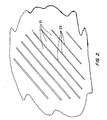
- FIG. 2 is a sketch of the dislocated lath structure of the alloy, with substantially parallel laths 21 consisting of grains of martensite-phase crystals, the laths separated by thin films 22 of retained austenite phase.
- This structure is the absence of carbides and of precipitates in general (including nitrides and carbonitrides), which appear in the prior art structures as additional needle-like structures of a considerably smaller size scale than the two phases shown and dispersed throughout the dislocated martensite laths. The absence of these precipitates contributes significantly to the corrosion resistance of the alloy.
- the desired microstructure is also obtained by casting such steels, and by cooling at rates fast enough to achieve the microstructure depicted in FIG. 2 , as stated above.
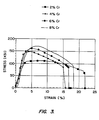
- FIG. 3 is a plot of stress vs. strain for the microstructures of four alloys within the scope of the present invention, all four of which are of the dislocated lath arrangement and free of autotempered products.
- Each alloy has 0.05% carbon, with varying amounts of chromium, the squares representing 2% chromium, the triangles 4%, the circles 6% and the smooth line 8%.
- the area under each stress-strain curve is a measure of the toughness of the steel, and it will be noted that each increase in the chromium content produces an increase in the area and hence the toughness, and yet all four chromium levels exhibit a curve with substantial area underneath and hence high toughness.
- the steel alloys of this invention are particularly useful in products that require high tensile strengths and are manufactured by processes involving cold forming operations, since the microstructure of the alloys lends itself particularly well to cold forming.
- Examples of such products are sheet metal for automobiles and wire or rods such as for radially reinforced automobile tires.
Landscapes
- Chemical & Material Sciences (AREA)
- Engineering & Computer Science (AREA)
- Materials Engineering (AREA)
- Mechanical Engineering (AREA)
- Metallurgy (AREA)
- Organic Chemistry (AREA)
- Crystallography & Structural Chemistry (AREA)
- Thermal Sciences (AREA)
- Physics & Mathematics (AREA)
- Heat Treatment Of Steel (AREA)
- Carbon And Carbon Compounds (AREA)
- Heat Treatment Of Sheet Steel (AREA)
- Heat Treatment Of Articles (AREA)
- Laminated Bodies (AREA)
- Heat Treatment Of Strip Materials And Filament Materials (AREA)
Abstract
Description
- This invention resides in the field of steel alloys, particularly those of high strength, toughness, corrosion resistance, and cold formability, and also in the technology of the processing of steel alloys to form microstructures that provide the steel with particular physical and chemical properties.
- Steel alloys of high strength and toughness and cold formability whose microstructures are composites of martensite and austenite phases are disclosed in the following-United States patents (all assigned to The Regents of the University of California):
-
4,170,497 (Gareth Thomas and Bangaru V. N. Rao ), issued October 9, 1979 on an application filed August 24,1977 -
4,170,499 (Gareth Thomas and Bangaru V. N. Rao), issued October 9, 1979 on an application filed September 14,1978 as a continuation in-part of the above application filed on August 24,1977 -
4,619,714 (Gareth Thomas, Jae-Hwan Ahn, and Nack-Joon Kim), issued October 28, 1986 on an application filed November 29,1984, as a continuation-in-part of an application filed on August 6,1984 -
4,671,827 (Gareth Thomas, Nack J. Kim, and Ramamoorthy Ramesh), issued June 9, 1987 on an application filed on October 11, 1985 - The microstructure plays a key role in establishing the properties of a particular steel alloy, and thus strength and toughness of the alloy depend not only on the selection and amounts of the alloying elements, but also on the crystalline phases present and their arrangement. Alloys intended for use in certain environments require higher strength and toughness, and in general a combination of properties that are often in conflict, since certain alloying elements that contribute to one property may detract from another.
- The alloys disclosed in the patents listed above are carbon steel alloys that have microstructures consisting of laths of martensite alternating with thin films of austenite and dispersed with fine grains of carbides produced by autotempering. The arrangement in which laths of one phase are separated by thin films of the other is referred to as a "dislocated lath" structure, and is formed by first heating the alloy into the austenite range, then cooling the alloy below a phase transition temperature into a range in which austenite transforms to martensite, accompanied by rolling to achieve the desired shape of the product and to refine the alternating lath and thin film arrangement. This microstructure is preferable to the alternative of a twinned martensite structure, since the lath structure has a greater toughness. The patents also disclose that excess carbon in the lath regions precipitates during the cooling process to form cementite (iron carbide, Fe3C) by a phenomenon known as "autotempering." These autotempered carbides are believed to contribute to the toughness of the steel.
- The dislocated lath structure produces a high-strength steel that is both tough and ductile, qualities that are needed for resistance to crack propagation and for sufficient formability to permit the successful fabrication of engineering components from the steel. Controlling the martensite phase to achieve a dislocated lath structure rather than a twinned structure is one of the most effective means of achieving the necessary levels of strength and toughness, while the thin films of retained austenite contribute the qualities of ductility and formability. Achieving this dislocated lath microstructure rather than the less desirable twinned structure requires a careful selection of the alloy composition, since the alloy composition affects the martensite start temperature, commonly referred to as Ms, which is the temperature at which the martensite phase first begins to form. The martensite transition temperature is one of the factors that determine whether a twinned structure or a dislocated lath structure will be formed during the phase transition.
- In many applications, the ability to resist corrosion is highly important to the success of the steel component. This is particularly true in steel-reinforced concrete in view of the porosity of concrete, and in steel that is used in moist environments in general. In view of the ever-present concerns about corrosion, there is a continuing effort to develop steel alloys with improved corrosion resistance. These and other matters in regard to the production of steel of high strength and toughness that is also resistant to corrosion are addressed by the present invention.
-
US 5129966 describes a method for enhancing the mechanical properties of a high strength, low alloy, low to medium carbon steel casting of the Fe/Cr/C type containing 0.1 to 0.5% Si by weight together with a small amount of Cu and Ni. This enhances by stability of the retained austenite based on quenching. The resulting fine grained microstructure also includes small quantities of Al, Ti and Nb. - The present invention provides a process for manufacturing a high-strength, corrosion-resistant, tough alloy carbon steel, comprising:
- (a) forming an alloy composition consisting of iron and at least one alloying element comprising carbon in proportions selected to provide said alloy composition with a martensite transition range having a martensite start temperature Ms (11) of at least 350°C;
- (b) heating said alloy composition to a temperature sufficiently high to cause austenitization thereof, under conditions causing said alloy composition to assume a homogeneous austenite phase (12) with all alloying elements in solution; and
- (c) cooling said homogeneous austenite phase (12) through said martensite transition range, to achieve a microstructure containing laths of martensite (21) alternating with films of retained austenite (22);
- said alloy composition comprises a carbon content of 0.01-0.35% by weight and either a chromium content of 1-13% by weight or a silicon content of 0.5-2% by weight;
- the proportions selected during stage (a) permit air-cooling of said alloy composition through said martensite transition range without forming carbides; the cooling of stage (c) is at a cooling rate to avoid the occurrence of autotempering and to achieve a microstructure containing substantially no carbides, nitrides, or carbonitrides.
- The invention further provides a product obtainable by the previously described process and comprising a carbon content of 0.01-0.35% by weight and either a chromium content of 1-13% by weight or a silicon content of 0.5-2% by weight, having a martensite start temperature Ms (11) of at least 350°C and wherein the microstructure comprises substantially no carbides, nitrides, or carbonitrides.
- The invention further provides a product obtainable by the previously described process and comprising from 0.05% to 0.2% by weight carbon and from 6% to 12% by weight chromium.
- The invention further provides a product obtainable by the previously described process and comprising from 0.05% to 0.2% by weight carbon and up to 2% by weight silicon.
- The invention further provides a product obtainable by the previously described process in which step (b) is performed at a maximum temperature of 1150°C and said films of retained austenite (22) constitute a maximum of 5% of said microstructure of step (c).
- The invention further provides a product obtainable by the previously described process, and wherein step (c) is performed by quenching in water, and comprising 0.05% to 0.1% by weight carbon, a member selected from the group consisting of silicon and chromium at a concentration of at least 2% by weight, and manganese at a concentration of at least 0.5% by weight, and wherein the microstructure comprises substantially no carbides, nitrides, or carbonitrides.
- The invention further provides a product obtainable by the previously described process, and wherein step (c) is performed by quenching in water, and comprising 0.05% to 0.1% by weight carbon, a member selected from the group consisting of silicon and chromium at a concentration of 2% by weight, and manganese at a concentration of 0.5% by weight, and wherein the microstructure comprises substantially no carbides, nitrides, or carbonitrides.
- The invention further provides a product obtainable by the previously described process, and wherein step (c) is performed by air cooling, and comprising 0.03% to 0.05% by weight carbon, chromium at a concentration of from 8% to 12% by weight, and manganese at a concentration of from 0.2% to 0.5% by weight, and wherein the microstructure comprises substantially no carbides, nitrides, or carbonitrides.
- It has now been discovered that corrosion in a dislocated lath structure can be reduced by eliminating the presence of precipitates such as carbides, nitrides, and carbonitrides from the structure, including those that are produced by autotempering and also including transformation products such as bainite and pearlite containing carbides, nitrides or carbonitrides of different morphologies depending on composition, cooling rate, and other parameters of the alloying process. It has been discovered that the interfaces between the small crystals of these precipitates and the martensite phase through which the,precipitates are dispersed promote corrosion by acting as galvanic cells, and that pitting of the steel begins at these interfaces. Accordingly, the present invention resides in part in an alloy steel with a dislocated lath microstructure that does not contain carbides, nitrides or carbonitrides, as well as a method for forming an alloy steel of this microstructure. The invention also resides in the discovery that this type of microstructure can be achieved by limiting the choice and the amounts of the alloying elements such that the martensite start temperature M is 3 50°C or greater. Still further, the invention resides in the discovery that while autotempering and other means of carbide, nitride or carbonitride precipitation in a dislocated lath structure can be avoided by a rapid cooling rate, certain alloy compositions will produce a dislocated lath structure free of autotempered products and precipitates in general simply by air cooling. These and other objects, features, and advantages of the invention will be better understood by the description that follows.
-
-
FIG. 1 is a phase transformation kinetic diagram demonstrating the alloy processing procedures and conditions of this invention. -
FIG. 2 is a sketch representing the microstructure of the alloy composition of this invention. -
FIG. 3 is a plot of stress vs. strain for four alloys in accordance with this invention. - Autotempering of an alloy composition occurs when a phase that is under stress due to supersaturation with an alloying element is relieved of its stress by precipitating the excess amount of the alloying element as a compound with another element of the alloy composition in such a manner that the resulting compound resides in isolated regions dispersed throughout the phase while the remainder of the phase reverts to a saturated condition. Autotempering will thus cause excess carbon to precipitate as iron carbide (Fe3C). If chromium is present as an additional alloying element, some of the excess carbon may also precipitate as trichromium dicarbide (Cr3C2), and similar carbides may precipitate with other alloying elements. Autotempering will also cause excess nitrogen to precipitate as either nitrides or carbonitrides. All of these precipitates are collectively referred to herein as "autotempering (or autotempered) products" and it is the avoidance of these products and other transformation products that include precipitates that is achieved by the present invention as a means of accomplishing its goal of lessening the susceptibility of the alloy to corrosion.
- The avoidance of the formation of autotempered products and carbides, nitrides and carbonitrides in general is achieved in accordance with this invention by appropriate selection of an alloy composition and a cooling rate through the martensite transition range. The phase transitions that occur upon cooling an alloy from the austenite phase are governed by the cooling rate at any particular stage of the cooling, and the transitions are commonly represented by phase transformation kinetic diagrams with temperature as the vertical axis and time as the horizontal axis, showing the different phases in different regions of the diagram, the lines between the regions representing the conditions at which transitions from one phase to another occur. The locations of the boundary lines in the phase diagram and thus the regions that are defined by the boundary lines vary with the alloy composition.
- An example of such a phase diagram is shown in
FIG. 1 . The martensite transition range is represented by the area below a horizontal line 11 which represents the martensite start temperature Ms, and theregion 12 above this line is the region in which the austenite phase prevails. A C-shapedcurve 13 within theregion 12 above the Ms line divides the austenite region into two subregions. Thesubregion 14 to the left of the "C" is that in which the alloy remains entirely in the austenite phase, while thesubregion 15 to the right of the "C" is that in which autotempered products and other transformation products that contain carbides, nitrides or carbonitrides of various morphologies, such as bainite and pearlite, form within the austenite phase. The position of the Ms line and the position and curvature of the "C" curve will vary with the choice of alloying elements and the amounts of each. - The avoidance of the formation of autotempering products is thus achieved by selecting a cooling regime which avoids intersection with or passage through the autotempered products subregion 15 (inside the curve of the "C"). If for example a constant cooling rate is used, the cooling regime will be represented by a straight line that is well into the
austenite regime 14 at time zero and has a constant (negative) slope. The upper limit of cooling rates that will avoid the autotempered products subregion 15 is represented by theline 16 in the Figure which is tangential to the "C" curve. To avoid the formation of autotempered products or carbides in general, a cooling rate must be used that is represented by a line to the left of the limit line 16 (i.e., one starting at the same time-zero point but having a steeper slope). - Depending on the alloy composition, therefore, a cooling rate that is sufficiently great to meet this requirement may be one that requires water cooling or one that can be achieved with air cooling. In general, if the levels of certain alloying elements in an alloy composition that is air-coolable and still has a sufficiently high cooling rate are lowered, it will be necessary to raise the levels of other alloying elements to retain the ability to use air cooling. For example, the lowering of one or more of such alloying elements as carbon, chromium, or silicon may be compensated for by raising the level of an element such as manganese.
- Alloy compositions for example that contain (i) from about 0.05% to about 0.1% carbon, (ii) either silicon or chomium at a concentration of at least about 2%, and (iii) manganese at a concentration of at least about 0.5%, all by weight (the remainder being iron), are preferably cooled by a water quench. Specific examples of these alloy compositions are (A) an alloy in which the alloying elements are 2% silicon, 0.5% manganese, and 0.1 % carbon, and (B) an alloy in which the alloying elements are 2% chromium, 0.5% manganese, and 0.05% carbon (all by weight with iron as the remainder). Examples of alloy compositions that can be cooled by air cooling while still avoiding the formation of autotempered products are those that contain as alloying elements 0.03% to 0.05% carbon, 8% to 12% chromium, and 0.2% to 0.5% manganese, all by weight (the remainder being iron). Specific examples of these alloy compositions are (A) those containing 0.05% carbon, 8% chromium, and 0.5% manganese, and (B) those containing 0.03% carbon, 12% chromium, and 0.2% manganese.
- As stated above, the avoidance of twinning during the phase transition is achieved by using an alloy composition that has a martensite start temperature Ms of 350°C or greater. A preferred means of achieving this result is by use of an alloy composition that contains carbon as an alloying element at a concentration of from 0.01% to 0.35%, more preferably from 0.05% to 0.20%, or from 0.02% to 0.15%, all by weight. Examples of other alloying elements that may also be included are chromium, silicon, manganese, nickel, molybdenum, cobalt, aluminum, and nitrogen, either singly or in combinations. Chromium is particularly preferred for its passivating capability as a further means of imparting corrosion resistance to the steel.
- When chromium is included, its content may vary, but in most cases chromium will constitute an amount within the range of 1% to 13% by weight. A preferred range for the chromium content is 6% to 12% by weight, and a more preferred range is about 8% to 10% by weight. When silicon is present, its concentration may vary as well. Silicon is preferably present at a maximum of 2% by weight, and most preferably from 0.5% to 2.0% by weight.
- In accordance with these procedures, the heating of the alloy composition to the austenite phase is preferably performed at a temperature up to about 1150°C, or more preferably within the range of from about 900°C to about 1150°C. The alloy is then held at this austenitization temperature for a sufficient period of time to achieve substantially full orientation of the elements according to the crystal structure of the austenite phase. Rolling is performed in a controlled manner at one or more stages during the austenitization and cooling procedures to deform the crystal grains and store strain energy into the grains, and to guide the newly forming martensite phase into a dislocated lath arrangement of martensite laths separated by thin films of retained austenite. Rolling at the austenitization temperature aids in the diffusion of the alloying elements to form a homogeneous austenite crystalline phase. This is generally achieved by rolling to reductions of 10% or greater, and preferably to reductions ranging from about 30% to about 60%.
- Partial cooling followed by further rolling may then take place, guiding the grains and crystal structure toward the dislocated lath arrangement, followed by final cooling in a manner that will achieve a cooling rate that avoids regions in which autotempered or transformation products will be formed, as described above. The thicknesses of the dislocated laths of martensite and the austenite films will vary with the alloy composition and the processing conditions and are not critical to this invention. In most cases, however, the retained austenite films will constitute from about 0.5% to about 15% by volume of the microstructure, preferably from about 3% to about 10%, and most preferably a maximum of about 5%.
FIG. 2 is a sketch of the dislocated lath structure of the alloy, with substantiallyparallel laths 21 consisting of grains of martensite-phase crystals, the laths separated bythin films 22 of retained austenite phase. Notable in this structure is the absence of carbides and of precipitates in general (including nitrides and carbonitrides), which appear in the prior art structures as additional needle-like structures of a considerably smaller size scale than the two phases shown and dispersed throughout the dislocated martensite laths. The absence of these precipitates contributes significantly to the corrosion resistance of the alloy. The desired microstructure is also obtained by casting such steels, and by cooling at rates fast enough to achieve the microstructure depicted inFIG. 2 , as stated above. -
FIG. 3 is a plot of stress vs. strain for the microstructures of four alloys within the scope of the present invention, all four of which are of the dislocated lath arrangement and free of autotempered products. Each alloy has 0.05% carbon, with varying amounts of chromium, the squares representing 2% chromium, thetriangles 4%, thecircles 6% and thesmooth line 8%. The area under each stress-strain curve is a measure of the toughness of the steel, and it will be noted that each increase in the chromium content produces an increase in the area and hence the toughness, and yet all four chromium levels exhibit a curve with substantial area underneath and hence high toughness. - The steel alloys of this invention are particularly useful in products that require high tensile strengths and are manufactured by processes involving cold forming operations, since the microstructure of the alloys lends itself particularly well to cold forming. Examples of such products are sheet metal for automobiles and wire or rods such as for radially reinforced automobile tires.
- The foregoing is offered primarily for purposes of illustration. Further modifications and variations of the various parameters of the alloy composition and the processing procedures and conditions may be made that still embody the basic and novel concepts of this invention. These will readily occur to those skilled in the art and are included within the scope of this invention.
Claims (16)
- A process for manufacturing a high-strength, corrosion-resistant, tough alloy carbon steel, comprising:(a) forming an alloy composition consisting of iron and at least one alloying element comprising carbon in proportions selected to provide said alloy composition with a martensite transition range having a martensite start temperature Ms (11) of at least 350°C;(b) heating said alloy composition to a temperature sufficiently high to cause austenitization thereof, under conditions causing said alloy composition to assume a homogeneous austenite phase (12) with all alloying elements in solution; and(c) cooling said homogeneous austenite phase (12) through said martensite transition range, to achieve a microstructure containing laths of martensite (21) alternating with films of retained austenite (22);characterised in that:said alloy composition comprises a carbon content of 0.01-0.35% by weight and either a chromium content of 1-13% by weight or a silicon content of 0.5-2% by weight;the proportions selected during stage (a) permit air-cooling of said alloy composition through said martensite transition range without forming carbides;the cooling of stage (c) is at a cooling rate to avoid the occurrence of autotempering and to achieve a microstructure containing substantially no carbides, nitrides, or carbonitrides.
- A process in accordance with claim 1 in which said carbon constitutes from 0.05% to 0.20% by weight of said alloy composition.
- A process in accordance with claim 1 in which said carbon constitutes from 0.02% to 0.15% by weight of said alloy composition.
- A process in accordance with claim 1 in which said chromium constitutes from 6% to 12% by weight of said alloy composition.
- A process in accordance with claim 1 in which said chromium constitutes from 8% to 10% by weight of said alloy composition.
- A process in accordance with claim 1 in which said at least one alloying element further comprises silicon of 2.0% by weight of said alloy composition.
- A process in accordance with claim 1 in which said at least one alloying element further comprises nitrogen, and said cooling rate of step (c) is sufficiently fast to achieve a microstructure containing laths of martensite (21) alternating with films of retained austenite (22) and containing substantially no carbides, nitrides, or carbonitrides.
- A process in accordance with claim 1 in which step (b) is performed at a temperature within the range of from 900°C to 1150°C.
- A process in accordance with claim 1 in which step (b) is performed at a temperature of a maximum of 1150°C.
- A process in accordance with claim 1 in which said films of retained austenite (22) constitute from 0.5% to 15% of said microstructure of step (c).
- A process in accordance with claim 1 in which said films of retained austenite (22) constitute from 3% to 10% of said microstructure of step (c).
- A process in accordance with claim 1 in which said films of retained austenite (22) constitute a maximum of 5% of said microstructure of step (c).
- A process in accordance with claim 1 in which said carbon constitutes from 0.05% to 0.1% by weight of said alloy composition and said at least one alloying element further comprises (i) a member selected from the group consisting of silicon and chromium at a concentration of at least 2% by weight and (ii) manganese at a concentration of at least 0.5% by weight, and step (c) is performed by quenching in water.
- A process in accordance with claim 1 in which said carbon constitutes from 0.05% to 0.1% by weight of said alloy composition and said at least one alloying element further comprises (i) a member selected from the group consisting of silicon and chromium at a concentration of 2% by weight and (ii) manganese at a concentration of 0.5% by weight, and step (c) is performed by quenching in water.
- A process in accordance with claim 1 in which said carbon constitutes from 0.03% to 0.05% by weight of said alloy composition and said at least one alloying element further comprises (i) chromium at a concentration of from 8% to 12% by weight and (ii) manganese at a concentration of from 0.2% to 0.5% by weight, and step (c) is performed by air cooling.
- A product obtainable by the process of claim 1 having a microstructure containing laths of martensite (21) alternating with films of retained austenite (22); comprising a carbon content of 0.01-0.35% by weight and either a chromium content of 1-13% by weight or a silicon content of 0.5-2% by weight, having a martensite start temperature Ms (11) of at least 350°C and wherein the microstructure comprises substantially no carbides, nitrides, or carbonitrides.
Priority Applications (1)
| Application Number | Priority Date | Filing Date | Title |
|---|---|---|---|
| CY20091101107T CY1109520T1 (en) | 1999-07-12 | 2009-10-26 | LOW CARBON STEELS FOR HIGHER MECHANICAL AND ANTI-CORRESPONDENT PROPERTIES |
Applications Claiming Priority (3)
| Application Number | Priority Date | Filing Date | Title |
|---|---|---|---|
| US14332199P | 1999-07-12 | 1999-07-12 | |
| US143321P | 1999-07-12 | ||
| PCT/US2000/008135 WO2001004365A1 (en) | 1999-07-12 | 2000-03-28 | Low-carbon steels of superior mechanical and corrosion properties |
Publications (3)
| Publication Number | Publication Date |
|---|---|
| EP1218552A1 EP1218552A1 (en) | 2002-07-03 |
| EP1218552A4 EP1218552A4 (en) | 2004-12-01 |
| EP1218552B1 true EP1218552B1 (en) | 2009-07-29 |
Family
ID=22503559
Family Applications (1)
| Application Number | Title | Priority Date | Filing Date |
|---|---|---|---|
| EP00918462A Expired - Lifetime EP1218552B1 (en) | 1999-07-12 | 2000-03-28 | Low-carbon steels of superior mechanical and corrosion properties |
Country Status (23)
| Country | Link |
|---|---|
| US (1) | US6273968B1 (en) |
| EP (1) | EP1218552B1 (en) |
| JP (3) | JP2003504514A (en) |
| KR (1) | KR100650408B1 (en) |
| CN (1) | CN1141403C (en) |
| AT (1) | ATE437967T1 (en) |
| AU (1) | AU768347B2 (en) |
| BR (1) | BR0006678A (en) |
| CA (1) | CA2377782C (en) |
| CY (1) | CY1109520T1 (en) |
| DE (1) | DE60042654D1 (en) |
| DK (1) | DK1218552T3 (en) |
| ES (1) | ES2329646T3 (en) |
| HK (1) | HK1048142B (en) |
| MX (1) | MXPA01013294A (en) |
| NO (1) | NO336435B1 (en) |
| NZ (1) | NZ516393A (en) |
| PT (1) | PT1218552E (en) |
| RU (1) | RU2232196C2 (en) |
| TR (1) | TR200200061T2 (en) |
| UA (1) | UA73311C2 (en) |
| WO (1) | WO2001004365A1 (en) |
| ZA (1) | ZA200200223B (en) |
Cited By (1)
| Publication number | Priority date | Publication date | Assignee | Title |
|---|---|---|---|---|
| CN109500099A (en) * | 2018-09-27 | 2019-03-22 | 东南大学 | The experimental method that a kind of pair of mild steel DSIT rolling mill practice optimizes |
Families Citing this family (14)
| Publication number | Priority date | Publication date | Assignee | Title |
|---|---|---|---|---|
| JP2003129190A (en) * | 2001-10-19 | 2003-05-08 | Sumitomo Metal Ind Ltd | Martensitic stainless steel and method for producing the same |
| US6709534B2 (en) * | 2001-12-14 | 2004-03-23 | Mmfx Technologies Corporation | Nano-composite martensitic steels |
| US6746548B2 (en) * | 2001-12-14 | 2004-06-08 | Mmfx Technologies Corporation | Triple-phase nano-composite steels |
| US20040149362A1 (en) * | 2002-11-19 | 2004-08-05 | Mmfx Technologies Corporation, A Corporation Of The State Of California | Cold-worked steels with packet-lath martensite/austenite microstructure |
| UA80009C2 (en) * | 2002-11-19 | 2007-08-10 | Mmfx Technologies Corp | Process for production of high-test, high-plastic alloyed carbonaceous steel |
| US7169239B2 (en) | 2003-05-16 | 2007-01-30 | Lone Star Steel Company, L.P. | Solid expandable tubular members formed from very low carbon steel and method |
| US7214278B2 (en) * | 2004-12-29 | 2007-05-08 | Mmfx Technologies Corporation | High-strength four-phase steel alloys |
| CN1328406C (en) * | 2005-06-22 | 2007-07-25 | 宁波浙东精密铸造有限公司 | Martensite wear resistant cast steel with film austenic toughened and its manufacturing method |
| US20070095266A1 (en) * | 2005-10-28 | 2007-05-03 | Chevron U.S.A. Inc. | Concrete double-hulled tank ship |
| US20090185943A1 (en) * | 2006-05-17 | 2009-07-23 | National Institute For Materials Science | Steel plate and steel plate coil |
| US8430075B2 (en) * | 2008-12-16 | 2013-04-30 | L.E. Jones Company | Superaustenitic stainless steel and method of making and use thereof |
| US20110236696A1 (en) * | 2010-03-25 | 2011-09-29 | Winky Lai | High strength rebar |
| WO2012153008A1 (en) | 2011-05-12 | 2012-11-15 | Arcelormittal Investigación Y Desarrollo Sl | Method for the production of very-high-strength martensitic steel and sheet or part thus obtained |
| US8978430B2 (en) | 2013-03-13 | 2015-03-17 | Commercial Metals Company | System and method for stainless steel cladding of carbon steel pieces |
Family Cites Families (18)
| Publication number | Priority date | Publication date | Assignee | Title |
|---|---|---|---|---|
| US2395608A (en) | 1943-12-10 | 1946-02-26 | United States Steel Corp | Treating inherently precipitationhardenable chromium-nickel stainless steel |
| US2778079A (en) | 1952-05-21 | 1957-01-22 | United States Steel Corp | Method of controlling the formation of crystals in molten metal as it solidifies |
| US4086107A (en) | 1974-05-22 | 1978-04-25 | Nippon Steel Corporation | Heat treatment process of high-carbon chromium-nickel heat-resistant stainless steels |
| SU595402A1 (en) * | 1976-12-24 | 1978-02-28 | Московский вечерний металлургический институт | Method of heat treatment of corrosion-resistant steels |
| US4170499A (en) | 1977-08-24 | 1979-10-09 | The Regents Of The University Of California | Method of making high strength, tough alloy steel |
| US4170497A (en) * | 1977-08-24 | 1979-10-09 | The Regents Of The University Of California | High strength, tough alloy steel |
| US4263063A (en) | 1979-07-05 | 1981-04-21 | The United States Of America As Represented By The United States Department Of Energy | Process for stabilizing dimensions of duplex stainless steels for service at elevated temperatures |
| US4619714A (en) | 1984-08-06 | 1986-10-28 | The Regents Of The University Of California | Controlled rolling process for dual phase steels and application to rod, wire, sheet and other shapes |
| US4613385A (en) | 1984-08-06 | 1986-09-23 | Regents Of The University Of California | High strength, low carbon, dual phase steel rods and wires and process for making same |
| US4671827A (en) * | 1985-10-11 | 1987-06-09 | Advanced Materials And Design Corp. | Method of forming high-strength, tough, corrosion-resistant steel |
| AU660928B2 (en) * | 1990-06-05 | 1995-07-13 | Ellwood Materials Technologies Company | High performance high strength low alloy steel |
| US5180450A (en) | 1990-06-05 | 1993-01-19 | Ferrous Wheel Group Inc. | High performance high strength low alloy wrought steel |
| JP2769422B2 (en) | 1993-04-19 | 1998-06-25 | 日立金属株式会社 | High strength stainless steel for fuel injection nozzle or needle of internal combustion engine, fuel injection nozzle for internal combustion engine and method of manufacturing the same |
| JPH06306538A (en) * | 1993-04-20 | 1994-11-01 | Kobe Steel Ltd | High strength steel wire excellent in weldability |
| DE19614407A1 (en) * | 1996-04-12 | 1997-10-16 | Abb Research Ltd | Martensitic-austenitic steel |
| JP3358951B2 (en) | 1996-09-10 | 2002-12-24 | 三菱重工業株式会社 | High strength, high toughness heat-resistant cast steel |
| DE19712020A1 (en) | 1997-03-21 | 1998-09-24 | Abb Research Ltd | Fully martensitic steel alloy |
| US5980662A (en) | 1997-04-22 | 1999-11-09 | Allegheny Ludlum Corporation | Method for batch annealing of austenitic stainless steels |
-
2000
- 2000-03-28 UA UA2002021101A patent/UA73311C2/en unknown
- 2000-03-28 KR KR1020027000385A patent/KR100650408B1/en not_active Expired - Fee Related
- 2000-03-28 NZ NZ516393A patent/NZ516393A/en not_active IP Right Cessation
- 2000-03-28 CN CNB008102104A patent/CN1141403C/en not_active Expired - Lifetime
- 2000-03-28 MX MXPA01013294A patent/MXPA01013294A/en active IP Right Grant
- 2000-03-28 EP EP00918462A patent/EP1218552B1/en not_active Expired - Lifetime
- 2000-03-28 US US09/537,000 patent/US6273968B1/en not_active Expired - Lifetime
- 2000-03-28 AU AU39265/00A patent/AU768347B2/en not_active Ceased
- 2000-03-28 HK HK03100032.7A patent/HK1048142B/en not_active IP Right Cessation
- 2000-03-28 DE DE60042654T patent/DE60042654D1/en not_active Expired - Lifetime
- 2000-03-28 PT PT00918462T patent/PT1218552E/en unknown
- 2000-03-28 TR TR2002/00061T patent/TR200200061T2/en unknown
- 2000-03-28 JP JP2001509563A patent/JP2003504514A/en not_active Withdrawn
- 2000-03-28 BR BR0006678-8A patent/BR0006678A/en not_active IP Right Cessation
- 2000-03-28 AT AT00918462T patent/ATE437967T1/en active
- 2000-03-28 DK DK00918462T patent/DK1218552T3/en active
- 2000-03-28 WO PCT/US2000/008135 patent/WO2001004365A1/en not_active Ceased
- 2000-03-28 CA CA002377782A patent/CA2377782C/en not_active Expired - Lifetime
- 2000-03-28 ES ES00918462T patent/ES2329646T3/en not_active Expired - Lifetime
- 2000-03-28 RU RU2002103374/02A patent/RU2232196C2/en not_active IP Right Cessation
-
2002
- 2002-01-10 ZA ZA200200223A patent/ZA200200223B/en unknown
- 2002-01-11 NO NO20020157A patent/NO336435B1/en not_active IP Right Cessation
-
2005
- 2005-07-26 JP JP2005216547A patent/JP4810153B2/en not_active Expired - Lifetime
-
2009
- 2009-10-26 CY CY20091101107T patent/CY1109520T1/en unknown
-
2011
- 2011-05-18 JP JP2011111912A patent/JP2011202280A/en active Pending
Cited By (1)
| Publication number | Priority date | Publication date | Assignee | Title |
|---|---|---|---|---|
| CN109500099A (en) * | 2018-09-27 | 2019-03-22 | 东南大学 | The experimental method that a kind of pair of mild steel DSIT rolling mill practice optimizes |
Also Published As
| Publication number | Publication date |
|---|---|
| TR200200061T2 (en) | 2002-06-21 |
| CA2377782C (en) | 2009-06-30 |
| NZ516393A (en) | 2003-01-31 |
| US6273968B1 (en) | 2001-08-14 |
| WO2001004365A1 (en) | 2001-01-18 |
| BR0006678A (en) | 2001-05-02 |
| KR100650408B1 (en) | 2006-11-28 |
| JP4810153B2 (en) | 2011-11-09 |
| PT1218552E (en) | 2009-10-22 |
| CN1141403C (en) | 2004-03-10 |
| CY1109520T1 (en) | 2014-08-13 |
| JP2006009155A (en) | 2006-01-12 |
| UA73311C2 (en) | 2005-07-15 |
| HK1048142B (en) | 2009-11-20 |
| RU2232196C2 (en) | 2004-07-10 |
| EP1218552A4 (en) | 2004-12-01 |
| HK1048142A1 (en) | 2003-03-21 |
| NO336435B1 (en) | 2015-08-17 |
| EP1218552A1 (en) | 2002-07-03 |
| AU768347B2 (en) | 2003-12-11 |
| MXPA01013294A (en) | 2003-09-04 |
| ZA200200223B (en) | 2003-03-26 |
| JP2003504514A (en) | 2003-02-04 |
| AU3926500A (en) | 2001-01-30 |
| JP2011202280A (en) | 2011-10-13 |
| CA2377782A1 (en) | 2001-01-18 |
| NO20020157D0 (en) | 2002-01-11 |
| NO20020157L (en) | 2002-03-11 |
| KR20020035833A (en) | 2002-05-15 |
| ES2329646T3 (en) | 2009-11-30 |
| CN1360640A (en) | 2002-07-24 |
| DK1218552T3 (en) | 2009-11-30 |
| ATE437967T1 (en) | 2009-08-15 |
| DE60042654D1 (en) | 2009-09-10 |
Similar Documents
| Publication | Publication Date | Title |
|---|---|---|
| KR102044693B1 (en) | High strength cold rolled steel sheet and method of producing such steel sheet | |
| EP2157203B1 (en) | High-strength steel sheet superior in formability | |
| CN101861406B (en) | High-strength cold-rolled steel sheet | |
| JP2011202280A (en) | Low-carbon steel of superior mechanical and corrosion properties | |
| US7754030B2 (en) | High strength steel sheet and method for production thereof | |
| EP1461467B1 (en) | Triple-phase nano-composite steels | |
| US7214278B2 (en) | High-strength four-phase steel alloys | |
| CN113316649A (en) | High-strength high-ductility complex-phase cold-rolled steel strip or plate | |
| KR20230026400A (en) | High-strength steel products and their manufacturing methods | |
| KR20240019756A (en) | High-strength cold-rolled steel sheet for automobiles with excellent overall formability and bending properties | |
| EP2831292A1 (en) | High strength cold rolled steel sheet and method of producing such steel sheet | |
| SE2350336A1 (en) | A high strength steel strip or sheet, and a method for producing the same | |
| HK1065342B (en) | Triple-phase nano-composite steels |
Legal Events
| Date | Code | Title | Description |
|---|---|---|---|
| PUAI | Public reference made under article 153(3) epc to a published international application that has entered the european phase |
Free format text: ORIGINAL CODE: 0009012 |
|
| 17P | Request for examination filed |
Effective date: 20020104 |
|
| AK | Designated contracting states |
Kind code of ref document: A1 Designated state(s): AT BE CH CY DE DK ES FI FR GB GR IE IT LI LU MC NL PT SE |
|
| AX | Request for extension of the european patent |
Free format text: AL;LT;LV;MK;RO;SI PAYMENT 20020104 |
|
| A4 | Supplementary search report drawn up and despatched |
Effective date: 20041018 |
|
| 17Q | First examination report despatched |
Effective date: 20050209 |
|
| GRAP | Despatch of communication of intention to grant a patent |
Free format text: ORIGINAL CODE: EPIDOSNIGR1 |
|
| GRAS | Grant fee paid |
Free format text: ORIGINAL CODE: EPIDOSNIGR3 |
|
| GRAA | (expected) grant |
Free format text: ORIGINAL CODE: 0009210 |
|
| AK | Designated contracting states |
Kind code of ref document: B1 Designated state(s): AT BE CH CY DE DK ES FI FR GB GR IE IT LI LU MC NL PT SE |
|
| AX | Request for extension of the european patent |
Extension state: AL LT LV MK RO SI |
|
| REG | Reference to a national code |
Ref country code: GB Ref legal event code: FG4D |
|
| REG | Reference to a national code |
Ref country code: CH Ref legal event code: EP |
|
| REG | Reference to a national code |
Ref country code: IE Ref legal event code: FG4D |
|
| REF | Corresponds to: |
Ref document number: 60042654 Country of ref document: DE Date of ref document: 20090910 Kind code of ref document: P |
|
| REG | Reference to a national code |
Ref country code: SE Ref legal event code: TRGR |
|
| REG | Reference to a national code |
Ref country code: PT Ref legal event code: SC4A Free format text: AVAILABILITY OF NATIONAL TRANSLATION Effective date: 20091014 |
|
| REG | Reference to a national code |
Ref country code: CH Ref legal event code: NV Representative=s name: KIRKER & CIE S.A. Ref country code: CH Ref legal event code: PFA Owner name: MMFX TECHNOLOGIES CORPORATION Free format text: MMFX STEEL CORPORATION OF AMERICA#2 CORPORATE PARK, SUITE 102#IRVINE, CA 92606 (US) -TRANSFER TO- MMFX TECHNOLOGIES CORPORATION#2415 CAMPUS DRIVE STE 100#IRVINE, CA 92612 (US) |
|
| REG | Reference to a national code |
Ref country code: GR Ref legal event code: EP Ref document number: 20090402468 Country of ref document: GR |
|
| REG | Reference to a national code |
Ref country code: HK Ref legal event code: GR Ref document number: 1048142 Country of ref document: HK |
|
| REG | Reference to a national code |
Ref country code: DK Ref legal event code: T3 Ref country code: ES Ref legal event code: FG2A Ref document number: 2329646 Country of ref document: ES Kind code of ref document: T3 |
|
| NLT1 | Nl: modifications of names registered in virtue of documents presented to the patent office pursuant to art. 16 a, paragraph 1 |
Owner name: MMFX TECHNOLOGIES CORPORATION |
|
| REG | Reference to a national code |
Ref country code: FR Ref legal event code: CA Ref country code: FR Ref legal event code: CD |
|
| RAP2 | Party data changed (patent owner data changed or rights of a patent transferred) |
Owner name: MMFX TECHNOLOGIES CORPORATION |
|
| PLBE | No opposition filed within time limit |
Free format text: ORIGINAL CODE: 0009261 |
|
| STAA | Information on the status of an ep patent application or granted ep patent |
Free format text: STATUS: NO OPPOSITION FILED WITHIN TIME LIMIT |
|
| 26N | No opposition filed |
Effective date: 20100503 |
|
| PG25 | Lapsed in a contracting state [announced via postgrant information from national office to epo] |
Ref country code: MC Free format text: LAPSE BECAUSE OF NON-PAYMENT OF DUE FEES Effective date: 20100331 |
|
| PG25 | Lapsed in a contracting state [announced via postgrant information from national office to epo] |
Ref country code: LU Free format text: LAPSE BECAUSE OF NON-PAYMENT OF DUE FEES Effective date: 20100328 |
|
| PGFP | Annual fee paid to national office [announced via postgrant information from national office to epo] |
Ref country code: IE Payment date: 20130312 Year of fee payment: 14 |
|
| PGFP | Annual fee paid to national office [announced via postgrant information from national office to epo] |
Ref country code: GR Payment date: 20130319 Year of fee payment: 14 |
|
| PGFP | Annual fee paid to national office [announced via postgrant information from national office to epo] |
Ref country code: CY Payment date: 20130320 Year of fee payment: 14 |
|
| PG25 | Lapsed in a contracting state [announced via postgrant information from national office to epo] |
Ref country code: CY Free format text: LAPSE BECAUSE OF NON-PAYMENT OF DUE FEES Effective date: 20140328 |
|
| REG | Reference to a national code |
Ref country code: LT Ref legal event code: MM9D Effective date: 20140328 |
|
| REG | Reference to a national code |
Ref country code: GR Ref legal event code: ML Ref document number: 20090402468 Country of ref document: GR Effective date: 20141002 |
|
| REG | Reference to a national code |
Ref country code: IE Ref legal event code: MM4A |
|
| PG25 | Lapsed in a contracting state [announced via postgrant information from national office to epo] |
Ref country code: GR Free format text: LAPSE BECAUSE OF NON-PAYMENT OF DUE FEES Effective date: 20141002 Ref country code: IE Free format text: LAPSE BECAUSE OF NON-PAYMENT OF DUE FEES Effective date: 20140328 |
|
| REG | Reference to a national code |
Ref country code: FR Ref legal event code: PLFP Year of fee payment: 17 |
|
| REG | Reference to a national code |
Ref country code: FR Ref legal event code: PLFP Year of fee payment: 18 |
|
| PGFP | Annual fee paid to national office [announced via postgrant information from national office to epo] |
Ref country code: FR Payment date: 20170213 Year of fee payment: 18 Ref country code: NL Payment date: 20170320 Year of fee payment: 18 Ref country code: SE Payment date: 20170313 Year of fee payment: 18 Ref country code: FI Payment date: 20170309 Year of fee payment: 18 Ref country code: CH Payment date: 20170314 Year of fee payment: 18 Ref country code: DE Payment date: 20170321 Year of fee payment: 18 |
|
| PGFP | Annual fee paid to national office [announced via postgrant information from national office to epo] |
Ref country code: GB Payment date: 20170322 Year of fee payment: 18 Ref country code: AT Payment date: 20170227 Year of fee payment: 18 Ref country code: BE Payment date: 20170124 Year of fee payment: 18 Ref country code: PT Payment date: 20170320 Year of fee payment: 18 Ref country code: DK Payment date: 20170310 Year of fee payment: 18 |
|
| PGFP | Annual fee paid to national office [announced via postgrant information from national office to epo] |
Ref country code: IT Payment date: 20170320 Year of fee payment: 18 Ref country code: ES Payment date: 20170214 Year of fee payment: 18 |
|
| REG | Reference to a national code |
Ref country code: DE Ref legal event code: R119 Ref document number: 60042654 Country of ref document: DE |
|
| REG | Reference to a national code |
Ref country code: DK Ref legal event code: EBP Effective date: 20180331 |
|
| PG25 | Lapsed in a contracting state [announced via postgrant information from national office to epo] |
Ref country code: PT Free format text: LAPSE BECAUSE OF NON-PAYMENT OF DUE FEES Effective date: 20180928 Ref country code: SE Free format text: LAPSE BECAUSE OF NON-PAYMENT OF DUE FEES Effective date: 20180329 Ref country code: FI Free format text: LAPSE BECAUSE OF NON-PAYMENT OF DUE FEES Effective date: 20180328 |
|
| REG | Reference to a national code |
Ref country code: CH Ref legal event code: PL |
|
| REG | Reference to a national code |
Ref country code: NL Ref legal event code: MM Effective date: 20180401 |
|
| REG | Reference to a national code |
Ref country code: AT Ref legal event code: MM01 Ref document number: 437967 Country of ref document: AT Kind code of ref document: T Effective date: 20180328 |
|
| GBPC | Gb: european patent ceased through non-payment of renewal fee |
Effective date: 20180328 |
|
| REG | Reference to a national code |
Ref country code: BE Ref legal event code: MM Effective date: 20180331 |
|
| PG25 | Lapsed in a contracting state [announced via postgrant information from national office to epo] |
Ref country code: NL Free format text: LAPSE BECAUSE OF NON-PAYMENT OF DUE FEES Effective date: 20180401 |
|
| PG25 | Lapsed in a contracting state [announced via postgrant information from national office to epo] |
Ref country code: AT Free format text: LAPSE BECAUSE OF NON-PAYMENT OF DUE FEES Effective date: 20180328 Ref country code: DE Free format text: LAPSE BECAUSE OF NON-PAYMENT OF DUE FEES Effective date: 20181002 |
|
| PG25 | Lapsed in a contracting state [announced via postgrant information from national office to epo] |
Ref country code: CH Free format text: LAPSE BECAUSE OF NON-PAYMENT OF DUE FEES Effective date: 20180331 Ref country code: IT Free format text: LAPSE BECAUSE OF NON-PAYMENT OF DUE FEES Effective date: 20180328 Ref country code: LI Free format text: LAPSE BECAUSE OF NON-PAYMENT OF DUE FEES Effective date: 20180331 Ref country code: BE Free format text: LAPSE BECAUSE OF NON-PAYMENT OF DUE FEES Effective date: 20180331 Ref country code: GB Free format text: LAPSE BECAUSE OF NON-PAYMENT OF DUE FEES Effective date: 20180328 |
|
| PG25 | Lapsed in a contracting state [announced via postgrant information from national office to epo] |
Ref country code: FR Free format text: LAPSE BECAUSE OF NON-PAYMENT OF DUE FEES Effective date: 20180331 |
|
| PG25 | Lapsed in a contracting state [announced via postgrant information from national office to epo] |
Ref country code: DK Free format text: LAPSE BECAUSE OF NON-PAYMENT OF DUE FEES Effective date: 20180331 |
|
| REG | Reference to a national code |
Ref country code: ES Ref legal event code: FD2A Effective date: 20190911 |
|
| PG25 | Lapsed in a contracting state [announced via postgrant information from national office to epo] |
Ref country code: ES Free format text: LAPSE BECAUSE OF NON-PAYMENT OF DUE FEES Effective date: 20180329 |