EP1218067B1 - Adjusting stiffness and flexibility in sports equipment - Google Patents
Adjusting stiffness and flexibility in sports equipment Download PDFInfo
- Publication number
- EP1218067B1 EP1218067B1 EP99943820A EP99943820A EP1218067B1 EP 1218067 B1 EP1218067 B1 EP 1218067B1 EP 99943820 A EP99943820 A EP 99943820A EP 99943820 A EP99943820 A EP 99943820A EP 1218067 B1 EP1218067 B1 EP 1218067B1
- Authority
- EP
- European Patent Office
- Prior art keywords
- spine
- stiffness
- flexibility
- sports equipment
- cavity
- Prior art date
- Legal status (The legal status is an assumption and is not a legal conclusion. Google has not performed a legal analysis and makes no representation as to the accuracy of the status listed.)
- Expired - Lifetime
Links
- 238000000034 method Methods 0.000 claims description 6
- 230000013011 mating Effects 0.000 claims 2
- 229910003460 diamond Inorganic materials 0.000 claims 1
- 239000010432 diamond Substances 0.000 claims 1
- 230000007246 mechanism Effects 0.000 description 33
- 239000000463 material Substances 0.000 description 11
- 230000000750 progressive effect Effects 0.000 description 9
- 230000000694 effects Effects 0.000 description 6
- 229910000831 Steel Inorganic materials 0.000 description 5
- 230000027455 binding Effects 0.000 description 5
- 238000009739 binding Methods 0.000 description 5
- 239000010959 steel Substances 0.000 description 5
- 230000006835 compression Effects 0.000 description 4
- 238000007906 compression Methods 0.000 description 4
- 239000000835 fiber Substances 0.000 description 4
- -1 woods Substances 0.000 description 4
- 238000005452 bending Methods 0.000 description 3
- 238000006073 displacement reaction Methods 0.000 description 3
- 229920000642 polymer Polymers 0.000 description 3
- 229920005989 resin Polymers 0.000 description 3
- 239000011347 resin Substances 0.000 description 3
- 230000035939 shock Effects 0.000 description 3
- OKTJSMMVPCPJKN-UHFFFAOYSA-N Carbon Chemical compound [C] OKTJSMMVPCPJKN-UHFFFAOYSA-N 0.000 description 2
- 238000010521 absorption reaction Methods 0.000 description 2
- 230000002411 adverse Effects 0.000 description 2
- 239000002131 composite material Substances 0.000 description 2
- 238000010276 construction Methods 0.000 description 2
- 229920001971 elastomer Polymers 0.000 description 2
- 239000011152 fibreglass Substances 0.000 description 2
- 239000002184 metal Substances 0.000 description 2
- 229910052751 metal Inorganic materials 0.000 description 2
- 230000003387 muscular Effects 0.000 description 2
- 230000002787 reinforcement Effects 0.000 description 2
- 229920001169 thermoplastic Polymers 0.000 description 2
- XLYOFNOQVPJJNP-UHFFFAOYSA-N water Substances O XLYOFNOQVPJJNP-UHFFFAOYSA-N 0.000 description 2
- ZOXJGFHDIHLPTG-UHFFFAOYSA-N Boron Chemical compound [B] ZOXJGFHDIHLPTG-UHFFFAOYSA-N 0.000 description 1
- 229920000049 Carbon (fiber) Polymers 0.000 description 1
- 241000288673 Chiroptera Species 0.000 description 1
- 235000009854 Cucurbita moschata Nutrition 0.000 description 1
- 240000001980 Cucurbita pepo Species 0.000 description 1
- 235000009852 Cucurbita pepo Nutrition 0.000 description 1
- 239000004593 Epoxy Substances 0.000 description 1
- 239000004677 Nylon Substances 0.000 description 1
- 239000004698 Polyethylene Substances 0.000 description 1
- 239000004743 Polypropylene Substances 0.000 description 1
- BZHJMEDXRYGGRV-UHFFFAOYSA-N Vinyl chloride Chemical compound ClC=C BZHJMEDXRYGGRV-UHFFFAOYSA-N 0.000 description 1
- 229910052796 boron Inorganic materials 0.000 description 1
- 239000004917 carbon fiber Substances 0.000 description 1
- POIUWJQBRNEFGX-XAMSXPGMSA-N cathelicidin Chemical compound C([C@@H](C(=O)N[C@@H](CCCNC(N)=N)C(=O)N[C@@H](CCCCN)C(=O)N[C@@H](CO)C(=O)N[C@@H](CCCCN)C(=O)N[C@@H](CCC(O)=O)C(=O)N[C@@H](CCCCN)C(=O)N[C@@H]([C@@H](C)CC)C(=O)NCC(=O)N[C@@H](CCCCN)C(=O)N[C@@H](CCC(O)=O)C(=O)N[C@@H](CC=1C=CC=CC=1)C(=O)N[C@@H](CCCCN)C(=O)N[C@@H](CCCNC(N)=N)C(=O)N[C@@H]([C@@H](C)CC)C(=O)N[C@@H](C(C)C)C(=O)N[C@@H](CCC(N)=O)C(=O)N[C@@H](CCCNC(N)=N)C(=O)N[C@@H]([C@@H](C)CC)C(=O)N[C@@H](CCCCN)C(=O)N[C@@H](CC(O)=O)C(=O)N[C@@H](CC=1C=CC=CC=1)C(=O)N[C@@H](CC(C)C)C(=O)N[C@@H](CCCNC(N)=N)C(=O)N[C@@H](CC(N)=O)C(=O)N[C@@H](CC(C)C)C(=O)N[C@@H](C(C)C)C(=O)N1[C@@H](CCC1)C(=O)N[C@@H](CCCNC(N)=N)C(=O)N[C@@H]([C@@H](C)O)C(=O)N[C@@H](CCC(O)=O)C(=O)N[C@@H](CO)C(O)=O)NC(=O)[C@H](CC=1C=CC=CC=1)NC(=O)[C@H](CC(O)=O)NC(=O)CNC(=O)[C@H](CC(C)C)NC(=O)[C@@H](N)CC(C)C)C1=CC=CC=C1 POIUWJQBRNEFGX-XAMSXPGMSA-N 0.000 description 1
- 229920001577 copolymer Polymers 0.000 description 1
- 230000001419 dependent effect Effects 0.000 description 1
- 238000010586 diagram Methods 0.000 description 1
- 230000008030 elimination Effects 0.000 description 1
- 238000003379 elimination reaction Methods 0.000 description 1
- 229920003247 engineering thermoplastic Polymers 0.000 description 1
- 230000002708 enhancing effect Effects 0.000 description 1
- HQQADJVZYDDRJT-UHFFFAOYSA-N ethene;prop-1-ene Chemical group C=C.CC=C HQQADJVZYDDRJT-UHFFFAOYSA-N 0.000 description 1
- 238000001125 extrusion Methods 0.000 description 1
- 206010016256 fatigue Diseases 0.000 description 1
- 229910002804 graphite Inorganic materials 0.000 description 1
- 239000010439 graphite Substances 0.000 description 1
- 229920000554 ionomer Polymers 0.000 description 1
- 150000002739 metals Chemical class 0.000 description 1
- 210000003205 muscle Anatomy 0.000 description 1
- 229920001778 nylon Polymers 0.000 description 1
- 229920001084 poly(chloroprene) Polymers 0.000 description 1
- 229920000058 polyacrylate Polymers 0.000 description 1
- 229920006122 polyamide resin Polymers 0.000 description 1
- 229920000728 polyester Polymers 0.000 description 1
- 229920000573 polyethylene Polymers 0.000 description 1
- 229920000139 polyethylene terephthalate Polymers 0.000 description 1
- 239000005020 polyethylene terephthalate Substances 0.000 description 1
- 229920000098 polyolefin Polymers 0.000 description 1
- 229920001155 polypropylene Polymers 0.000 description 1
- 230000001105 regulatory effect Effects 0.000 description 1
- 229920003987 resole Polymers 0.000 description 1
- 238000000926 separation method Methods 0.000 description 1
- 239000011359 shock absorbing material Substances 0.000 description 1
- 229910052710 silicon Inorganic materials 0.000 description 1
- 239000010703 silicon Substances 0.000 description 1
- 239000007787 solid Substances 0.000 description 1
- 230000037078 sports performance Effects 0.000 description 1
- 235000020354 squash Nutrition 0.000 description 1
- 239000000725 suspension Substances 0.000 description 1
- 229920001187 thermosetting polymer Polymers 0.000 description 1
- 239000004634 thermosetting polymer Substances 0.000 description 1
- 208000016254 weariness Diseases 0.000 description 1
Images


Classifications
-
- A—HUMAN NECESSITIES
- A63—SPORTS; GAMES; AMUSEMENTS
- A63C—SKATES; SKIS; ROLLER SKATES; DESIGN OR LAYOUT OF COURTS, RINKS OR THE LIKE
- A63C5/00—Skis or snowboards
- A63C5/06—Skis or snowboards with special devices thereon, e.g. steering devices
- A63C5/07—Skis or snowboards with special devices thereon, e.g. steering devices comprising means for adjusting stiffness
-
- A—HUMAN NECESSITIES
- A63—SPORTS; GAMES; AMUSEMENTS
- A63B—APPARATUS FOR PHYSICAL TRAINING, GYMNASTICS, SWIMMING, CLIMBING, OR FENCING; BALL GAMES; TRAINING EQUIPMENT
- A63B60/00—Details or accessories of golf clubs, bats, rackets or the like
- A63B60/06—Handles
- A63B60/22—Adjustable handles
- A63B60/26—Adjustable handles with adjustable stiffness
-
- A—HUMAN NECESSITIES
- A63—SPORTS; GAMES; AMUSEMENTS
- A63B—APPARATUS FOR PHYSICAL TRAINING, GYMNASTICS, SWIMMING, CLIMBING, OR FENCING; BALL GAMES; TRAINING EQUIPMENT
- A63B59/00—Bats, rackets, or the like, not covered by groups A63B49/00 - A63B57/00
- A63B59/20—Bats, rackets, or the like, not covered by groups A63B49/00 - A63B57/00 having means, e.g. pockets, netting or adhesive type surfaces, for catching or holding a ball, e.g. for lacrosse or pelota
-
- A—HUMAN NECESSITIES
- A63—SPORTS; GAMES; AMUSEMENTS
- A63B—APPARATUS FOR PHYSICAL TRAINING, GYMNASTICS, SWIMMING, CLIMBING, OR FENCING; BALL GAMES; TRAINING EQUIPMENT
- A63B59/00—Bats, rackets, or the like, not covered by groups A63B49/00 - A63B57/00
- A63B59/70—Bats, rackets, or the like, not covered by groups A63B49/00 - A63B57/00 with bent or angled lower parts for hitting a ball on the ground, on an ice-covered surface, or in the air, e.g. for hockey or hurling
-
- A—HUMAN NECESSITIES
- A63—SPORTS; GAMES; AMUSEMENTS
- A63B—APPARATUS FOR PHYSICAL TRAINING, GYMNASTICS, SWIMMING, CLIMBING, OR FENCING; BALL GAMES; TRAINING EQUIPMENT
- A63B59/00—Bats, rackets, or the like, not covered by groups A63B49/00 - A63B57/00
- A63B59/80—Circular bats or paddles not provided for in groups A63B59/20 - A63B59/70
-
- A—HUMAN NECESSITIES
- A63—SPORTS; GAMES; AMUSEMENTS
- A63B—APPARATUS FOR PHYSICAL TRAINING, GYMNASTICS, SWIMMING, CLIMBING, OR FENCING; BALL GAMES; TRAINING EQUIPMENT
- A63B60/00—Details or accessories of golf clubs, bats, rackets or the like
- A63B60/002—Resonance frequency related characteristics
-
- A—HUMAN NECESSITIES
- A63—SPORTS; GAMES; AMUSEMENTS
- A63B—APPARATUS FOR PHYSICAL TRAINING, GYMNASTICS, SWIMMING, CLIMBING, OR FENCING; BALL GAMES; TRAINING EQUIPMENT
- A63B60/00—Details or accessories of golf clubs, bats, rackets or the like
- A63B60/0081—Substantially flexible shafts; Hinged shafts
-
- A—HUMAN NECESSITIES
- A63—SPORTS; GAMES; AMUSEMENTS
- A63B—APPARATUS FOR PHYSICAL TRAINING, GYMNASTICS, SWIMMING, CLIMBING, OR FENCING; BALL GAMES; TRAINING EQUIPMENT
- A63B2102/00—Application of clubs, bats, rackets or the like to the sporting activity ; particular sports involving the use of balls and clubs, bats, rackets, or the like
- A63B2102/24—Ice hockey
-
- A—HUMAN NECESSITIES
- A63—SPORTS; GAMES; AMUSEMENTS
- A63B—APPARATUS FOR PHYSICAL TRAINING, GYMNASTICS, SWIMMING, CLIMBING, OR FENCING; BALL GAMES; TRAINING EQUIPMENT
- A63B53/00—Golf clubs
- A63B53/08—Golf clubs with special arrangements for obtaining a variable impact
-
- A—HUMAN NECESSITIES
- A63—SPORTS; GAMES; AMUSEMENTS
- A63B—APPARATUS FOR PHYSICAL TRAINING, GYMNASTICS, SWIMMING, CLIMBING, OR FENCING; BALL GAMES; TRAINING EQUIPMENT
- A63B53/00—Golf clubs
- A63B53/10—Non-metallic shafts
-
- A—HUMAN NECESSITIES
- A63—SPORTS; GAMES; AMUSEMENTS
- A63B—APPARATUS FOR PHYSICAL TRAINING, GYMNASTICS, SWIMMING, CLIMBING, OR FENCING; BALL GAMES; TRAINING EQUIPMENT
- A63B60/00—Details or accessories of golf clubs, bats, rackets or the like
- A63B60/06—Handles
- A63B60/22—Adjustable handles
- A63B60/24—Weighted handles
-
- A—HUMAN NECESSITIES
- A63—SPORTS; GAMES; AMUSEMENTS
- A63B—APPARATUS FOR PHYSICAL TRAINING, GYMNASTICS, SWIMMING, CLIMBING, OR FENCING; BALL GAMES; TRAINING EQUIPMENT
- A63B60/00—Details or accessories of golf clubs, bats, rackets or the like
- A63B60/48—Details or accessories of golf clubs, bats, rackets or the like with corrugated cross-section
-
- A—HUMAN NECESSITIES
- A63—SPORTS; GAMES; AMUSEMENTS
- A63B—APPARATUS FOR PHYSICAL TRAINING, GYMNASTICS, SWIMMING, CLIMBING, OR FENCING; BALL GAMES; TRAINING EQUIPMENT
- A63B60/00—Details or accessories of golf clubs, bats, rackets or the like
- A63B60/50—Details or accessories of golf clubs, bats, rackets or the like with through-holes
-
- A—HUMAN NECESSITIES
- A63—SPORTS; GAMES; AMUSEMENTS
- A63B—APPARATUS FOR PHYSICAL TRAINING, GYMNASTICS, SWIMMING, CLIMBING, OR FENCING; BALL GAMES; TRAINING EQUIPMENT
- A63B60/00—Details or accessories of golf clubs, bats, rackets or the like
- A63B60/54—Details or accessories of golf clubs, bats, rackets or the like with means for damping vibrations
Definitions
- the user may choose a particular piece of sports equipment having a desired stiffness or flexibility characteristic and, during play, switch to a different piece of sports equipment that is slightly more flexible or stiffer to suit changing playing conditions or to help compensate for weariness or fatigue. Such switching, of course, is subject to availability of different pieces of sports equipment from which to choose.
- US-A-4,105,205 relates to a racket having a handle provided with one or more cylindrical cavities wherein an elongated I-shaped beam is located.
- One end of said beam is provided with a cylindrical shaft rotatably carried in said cavity.
- a stud shaft is provided at the other end of said beam and is fixedly mounted in the open end of said cavity. This open end is blocked by a closure through which extends a small shaft integrally formed with said beam for regulating the stiffness of said racket handle. If the shaft is rotated by the knob so that the long dimension of the beam extends at a right angle to the plane of the frame, the racket will have a stiff quality.
- US-A-4,577,886 concerns an adjustable flexi ski including steel strips wherein the tension can be selectively adjusted by means of a rear tensioning assembly and a forward tensioning assembly. Said steel strips are connected to a steel thrust and to a sidewall of the ski through flexible shaft aligned in a fibreglass housing. A slidable steel anchor is welded to the steel strip and has a threaded shaft connected to said flexible shaft in order to adjust the tension in the ski through the ski sidewall.
- the sports equipment may have a shaft with an elongated cavity, an elongated flexure resistance spine, two locking elements that secure the spine against rotation at two spaced apart locations within the cavity.
- the spine is stiffer and less flexible in one direction than in another.
- a further aspect of the invention resides in a method of varying stiffness and flexibility, comprising providing sports equipment having an elongated cavity; imparting stiffness and flexibility variations within the cavity so the sports equipment becomes more stiff and less flexible in one direction than in a different direction; and securing against rotation at two spaced apart locations within the cavity while imparting the stiffness ad flexibility variations.
- Fig. 1 shows a hockey stick 10, which has a body that includes a hollow shaft 12 and blade 14. Also shown is a flexure stiffening rod or spine 16 extending through a majority of the length of the hollow shaft 12. The top open end of the shaft 12 is closed by a cap 18.
- the spine 16 is secured at both ends in place by respective locking mechanisms 20, 22.
- Spaced along the length of the shaft 12 and the spine 16 are a plurality of spaced apart centering collars 24.
- the centering collars 24 may be made of rubber or other shock absorbing material, such as neoprene or silicon.
- the centering collars each have a relatively tight tolerance and low coefficient of friction to facilitate the function of guiding the spine 16 into position.
- splined collars may be used to prevent the spine 16 from deflecting when severely flexed and enhancing holding power in high stress applications.
- the advantage of securing the spine 16 at both ends is the elimination of torsion or roll-over of the spine 16 from twisting forces otherwise present during puck play with the hockey stick 10.
- the locking of the spine in two places such as at the vicinity of the ends ensures the flexible rigidity performance at each selected (manual) setting of the spine orientation relative to the shaft 12.
- the flexural and rigidity mechanical responses that are selected become manually locked into place. This ensures the setting will not jump out of its selected mechanical position from the performance desired due to twisting forces otherwise present.
- the locking mechanisms 20, 22 become anchor points, which mitigate energy absorption or attenuation of energy in the spine 16.
- the spine 16 is held in compression within the shaft 12 by the locking mechanisms 20, 22 when a flexural resistance selection setting is locked. Such is advantageous in that energy is transmitted out of the shaft 12 at its terminus such as the hockey blade instead of being absorbed by the spine 16 itself.
- the dead stick feel is mitigated by minimizing energy shock absorption by the spine 16. Instead, energy is reflected back into the object such as a hockey puck.
- energy shock is mechanically achieved by the locking mechanisms 20, 22, which expand to lock in the flexural resistance setting, thereby compressing a spring material.
- force loading of the spring is believed to produce the reflection of energy when the hockey stick is used to strike the object such as the puck.
- the centering collars 24 are used to center the spine 16 within the shaft 12 so as to mitigate or absorb any attenuation of the spine 16 during the strike-impact event with an object, thereby further minimizing the dead stick feel.
- the locking mechanism 20 is shown in greater detail in Fig. 2. It has a positioning base plate 26 with locking teeth, a selecting knurl 28 with positioning locking teeth that engage those of the positioning base plate 26 and with a threaded portion 30, a knurled lock ring 32 threaded onto the threaded portion 30, a knurl 34 threaded onto the threaded portion 30, and a compression spring 38.
- the knurled lock ring 32 is between the selecting knurl 28 and the knurl 34.
- the knurl 34 is arranged to compress the spring 38 when fully unscrewed, but still engaged to the compression head 36 at the end of the knurl 28.
- the knurl 28 has the threaded portion 30 extended from it and the unthreaded end 36 more distal and extending from the threaded portion 30.
- the locking mechanism 22 includes serrated teeth assembly that engage to lock into position, but is able to rotate as is the spine 16 by 360 degrees when freed.
- the flexure resistance spine 16 may have an I-shape 50, or any other a variety of other types of shapes. As best seen in Fig. 5, the I-shape 50 changes its relative position within the shaft 12 dependent upon the position that it is rotated to enter in registry with the settings.
- Neighboring the upper end of the shaft may be placed a designation to signify a reference location.
- markings may be spaced about the periphery at the top of the flexure resistance spine 16, each representing different graduation in stiffness or flexibility.
- This protruding portion may have the markings signifying the different degrees of stiffness or flexibility.
- the reference location designation should be located so when aligned with the marking on the flexure resistance spine signifying the most stiff or most flexible, the flexure resistance spine orientation coincides with that needed to impart the most stiff or most flexible characteristic to the shaft out of all the settings.
- Fig. 6 shows the locking mechanism 20 in an extended condition to effect locking.
- an extension distance 40 which is shown to define a gap that spaces apart the knurl 28 and the knurled lock ring 32.
- Fig. 7 shows the locking mechanism 20 in a compressed assembly condition with an unloaded spring 38 and no appreciable extension distance 40 being present.
- the compression head 36 is at a lower relative position in Fig. 7 than in Fig. 6, that is with respect to the end chamber 42 that contains the spring 38.
- Fig. 8 shows the relationship with respect Figs. 6 and 7 between the spring displacement distance 44, the travel distance 46 and the adjustable distance 48.
- the spring displacement distance 40 is the amount of distance traveled by the spring while displacing from a compressed condition to a relaxed condition.
- the travel distance 46 is essentially the extension distance 40 of Fig. 6, but represents the distance the knurl 28 travels.
- the adjustable distance 48 represents the separation distance between the serrated teeth.
- the spring displacement distance 42 is the same dimension as the travel distance 44, which in turn is the same dimension as the adjustable distance 48.
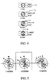
- Fig. 9 shows a golf club 56 containing the spine 16 of Fig. 1 together with a uni-directional clutch mechanism 60 that employs a uni-direction rotation to enter into a locking condition analogous to the socket wrench concept.
- the spine is dimensioned to fit within the golf club shaft, which is thinner than a hockey stick.
- the top end of the golf club 56 has a rigidity selector 58 that allows one direction of rotation of the spine.
- the unidirectional clutch mechanism 60 is at a location neighboring the rigidity selector 58 in the vicinity of the top portion of the golf club 56.
- the unidirectional clutch mechanism 60 is within the golf club outer wall 64 and includes a snap ring 66 whose snap-fit fingers 68 engage in a lock ring anchor 70 that is bounded by the golf club outer wall 64.
- the force components V1 are shown as well.
- each turn from one snap-fit finger to its neighbor would traverse an angular sweep of 30 degree.
- the spine 16 is shown here having a flexural I-shape movable in association with the rotatable movement of the snap ring 66.
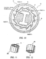
- Figs. 11 and 12 respectively show right and left handed unidirectional clutch mechanisms.
- Fig. 11 shows a perspective view of the right hand unidirectional clutch mechanism 60R (and Fig. 12 is of the left hand unidirectional clutch mechanism 60L) with central I-beam shape spine 16 used in the lower portion of the golf club 56.
- This provides for two spaced apart locations along the length of the shaft of the golf club 56 to secure the spine 16. These two locking locations lock the torsion of the golf club shaft, creating a more accurate golf club, because the rotation of the head of the club is redundantly and mechanically prevented from rotating.
- Fig. 13 shows the manner in which the unidirectional clutch mechanism is assembled.
- the lock ring 66 is inserted into the snap ring 68 such that the snap-fit fingers 68 are accommodated in respective recesses in the snap ring 68 that conform in shape to that of the snap-fit fingers.
- the snap-fit fingers are arranged one after another so as to be directed in a clockwise direction. Note that a left hand clutch mechanism such as that of Fig. 12 would have the snap-fit fingers direct in a counter-clockwise direction.
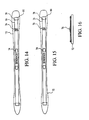
- Figs. 14-16 show the flexure resistance spine 16 being used on a pair of skis 72 having bindings 74.
- a tension rigidity selector is provided in the form of a lever 76 that may be lifted upwardly from the position shown in Figs. 14-16.
- the flexure resistance spine 16 simultaneously rotates to change the flexural performance of the skis at the ends 78, 80.
- the lever 76 may be locked to secure the changed flexural performance position by folding the lever to the left or right side in a direction perpendicular to the vertical lift.
- the spines 16 are arrange to the outside of the binding 74 footprint.
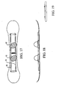
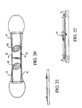
- Figs. 17-22 show arrangements for using the flexure resistance spines 16 on snowboards, thereby providing a dynamic tensioning system for slalom and mogul terrain.
- the spines 16 are arranged beneath the binding footprints 82.
- the spines 16 are arranged to the outside of the binding footprints 82.
- a lever 84 is provided that is analogous to the lever 76 of Figs. 14-16 is operative in the same manner to rotate the flex spines 16 and to secure the position by looking in position.
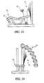
- Figs. 23 and 24 show arrangements for using the flexure resistance spines 16 of universal benches 90 designed for exercising that strengthens the quadriceps, hamstrings, chest, triceps, biceps and back muscles.
- the cross section wall thickness of the spines 16 in this embodiment is proportional to the flexural resistance for ovoid geometry 92 orientation of the spines 16.
- the end of the spine 16 is secured to a resistance wire or cable to tension at 94 for quadriceps and hamstring exercises and at 96 for the chest, triceps, biceps and back exercises.
- the spines may be used in any type of exercise machine or weight bench that exerts resistance to muscular forces.
- Figs. 25-27 show the use of the flexural resistance spine 16 being an extrusion with the main frame rod 100 of a bicycle 102.
- torsion, or bending of the main bicycle frame rod occurs as cyclists shift their weight while riding and the force exerted upon the pedals.
- access is provided to rotate the spine 16, which may have an I-shape (see Fig. 28), into any one of various different relative orientations.
- the maximum rigidity and minimum torsion is attained with the orientation of the uppermost I-beam orientation shown and the minimum rigidity and maximum torsion is attained with the orientation of the lowermost I-beam orientation shown.
- the cyclist may adjust to optimize riding conditions in view of weight shifting and pedal forces. For instance, the adjustment of the flexural resistance spine 16 provides the cyclist with the ability to alter ride conform and the ability to absorb shocks transmitted from the wheels in a manner analogous to a suspension system.
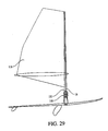
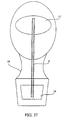
- Figs. 29-31 show the flexural resistance spine 16 is use within the mast 110 of a windsurf board 112.
- the relative orientations that the spine 16 may be rotated into is shown generally at 114 in Fig. 30, which are individually represented in Fig. 31 with respect to the I-beam shape.
- the sail 116 is arranged so that the wind may exert a perpendicular force to the sail.
- the mast 110 may be formed of a composite material whose center includes the spine 16.
- a flex position locking collar 118 is provided so that the I-beam shape of the spine 16 is fixed to the a desired flexural setting and moves with the windsurf board's tacking, windward and leeward sail movements and maintains flex position within the mast.
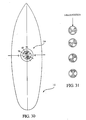
- Figs. 32-35 show the spines 16 arranged in scuba fins 120. Each spine may be rotated to the desired relative orientation. As seen in Fig. 35, such variable orientations change the relative position of the I-shape configuration that runs the full length of the spine 16.
- At each end region of the spine 16 are respective locking elements 122, 124 that engage the spine 16 to lock the same in position relative to its orientation on the scuba fin.
- the locking elements 122, 124 may each be annular and friction fit onto the spine.
- the bottom of the scuba fin may have a configuration adapted to friction fit the locking elements in position.
- the spine 16 is pulled linearly out of friction fit engagement with the locking elements 122, 124, rotated such as in the clockwise direction shown to the desired relative position, and then pushed linearly to engage with the locking elements 122, 124.
- Figs. 36 and 37 show the spine 16 used on footwear such as a hiking shoe 130.
- the sole and heel of the shoe are each equipped with cavities 132, 134 between which extends the spine 16, which may have an I-beam shape for its entire length or another geometry that provides different stiffness coefficients in different directions.
- a force plate may be inserted within each of the cavities to receive the locking elements 122, 124. Locking may be effected with a rachet engagement to vary the relative position of the I-beam shape.
- Figs. 39, 40, 41, 42 and 43 show different suitable geometries that the spine in any of the embodiments may have. By rotating such geometries, the stiffness or torsion characteristics in particular directions may vary.
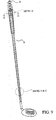
- Figs. 43-45 show a tapered spine 140 that is fitted into a hollow cavity of the fishing rod 142.
- the tapered spine 140 extends from the proximal butt 144 of the handle of the fishing rod 142 to the distal tip 146 of the fishing rod 142.
- the fishing rod is of a two-piece construction as opposed to a one-piece as shown, then either two separate tapered spines are used (one for the upper half of rod and the other for the lower half of the rod) or the two separate tapered spines screw or otherwise attach together when the upper and lower halves of the fishing rod are joined so as to in effect provide for a continuous spine.
- Locking elements are arranged neighboring the butt of the handle of the fishing rod and as far as feasible toward the tip of the fishing rod.
- the locking elements may be the same as for the hockey stick or golf club embodiments, for instance, except they need to lock to a tapered spine.
- Fig. 45 shows the relative position of the spine during its rotation within the fishing rod.
- the I-shape cross-section 148 that is shown for the spine is exemplary only.
- Figs. 46-49 show a hockey stick 150 with an elongated cavity 152 into which is inserted an elongated double flute or tapered spine 154. Opposite ends of the spine 154 are secured with a socket ratchet 156 at one end and knurl gears 158 and locking pin 160 at the other end.
- Figs. 50 and 51 show an exemplary spine 154 that has an ellipsoidal I-beam shape 162 with asymmetric cross-sections.
- the spine 154 is double fluted or tapered to increase or decrease the mechanical flex characteristics, e.g., the thinner or flatter portion has the smaller minor ellipsoid axis whose cross-section is of double wall I-beam shape and is extremely rigid.
- the wider or ovoid portion has the larger minor ellipsoid axis whose cross-section is of double wall I-beam shape that is less rigid, more flexible.
- Fig. 51 shows the relative orientation of the spine rotating from the top to the bottom views of high flex to low flex.
- Each of these pieces of sports equipment as exemplified by the embodiments may be in a sense split up into multiple sections, each with its own adjustable flexibility and stiffness.
- the flexure resistance spines 16 may be stepped or tapered and need not be of uniform dimension.
- the cross-sectional shape of the flexure resistance spine 16 is common in each of the embodiments, the actual dimensions may vary depending upon the actual piece of sports equipment to which the flexure resistance spine is to be used. In all embodiments, it is preferred that the length of the flexure resistance spine reach a majority of the length of the piece of sports equipment to which it is used and that the spine be secured at two spaced apart locations (neighboring respective ends of the spine).
- the sports equipment such as a hockey stick or a lacrosse stick will be referred to as a stick; sports equipment such as a baseball bat, softball bat and cricket bat will be referred to as a bat; sports equipment such as a tennis racket, paddleball racket, squash racket, court tennis racket and badminton racket will be referred to as a racket; golf club will be referred to as a club; an archery bow will be referred to as a bow; a fishing rod with be referred to as a rod; a water ski, a downhill ski and a cross-country ski will be referred to as a ski; a snow board or skiboard will be referred to as a board; a snow skate will be referred to as a skate; a pole vault pole and a ski pole will be referred to as a pole; an oar or paddle will be referred to collectively as a paddle; a polo mallet will be referred to
- a reference marking may be provided at the end of the sports equipment neighboring where the flexure resistance spine 16 protrudes.
- the reference marking is arranged to signify the greatest stiffness or flexibility for a particular direction when an appropriate marking or indicia of the flexure resistance spine is turned to be coincident with the reference marking.
- the flexure resistance spine 16 be rotatable in response to manual turning forces. If not, however, then the flexure resistance spine 16 may be removed from its position in the sports equipment, turned to the desired orientation and then inserted once more back into the cavity.
- the actual configuration of the flexure resistance spine 16 may be any desired configuration in which the stiffness in one direction is greater than in a different direction and the flexibility is greater in the different direction than the one direction. That is, where both the one direction and the different direction are directed transverse to the longitudinal axis, in contrast to being coincident with it.
- the materials of the flexure resistance spine may be fabricated of any material having desired flexibility and stiffness characteristics.
- Such materials include, but are not limited to, metals, woods, rubber, thermoplastic polymers, thermoset polymers, ionomers, and the like.
- the thermoplastic polymers include the polyamide resins such as nylon; the polyolefins such as polyethylene, polypropylene, as well as their copolymers such as ethylene-propylene; the polyesters such as polyethylene terephthalate and the like; vinyl chloride polymers and the like, and the polycarbonite resins, and other engineering thermoplastics such as ABS class or any composites using these resins or polymers.
- the thermoset resins include acrylic polymers, resole resins, epoxy polymers, and the like.
- Polymeric materials may contain reinforcements that enhance the stiffness or flexure of the flexure resistance spine 16.
- Some reinforcements include fibers such as fiberglass, metal, polymeric fibers, graphite fibers, carbon fibers, boron fibers and the like.
- the protruding portion of the flexure resistance spine 16 may be freely accessible from the end of the piece of sports equipment or be enclosed by a suitable cap or handle end so that removal of this cap or handle would be necessary to gain access to the flexure resistance spine from the cavity and effect its removal.
- the flexure resistance spine is freely turned within the cavity, then its removal would not be necessary to alter the direction of stiffness and flexibility if provision were made so that rotation of the cap or handle resulted in rotation of the flexure resistance spine.
- having the ability to change the flexibility and stiffness of the sports equipment affords an additional advantage in that it may be used as a training aid, allowing the player or teacher to instantly change only the flex and stiffness characteristics of the sports equipment, without altering the swing weight, grip size, feel, etc. This permits the focus of training to be only on the flex and not other factors.
- the spine 16 may be double walled, tapered longitudinally, asymmetric in cross-section, of variable shape along its length such as circular to elliptical to triangular, flared and/or fluted. Further, depending upon the application, the spine may be constructed of materials to render them relative more rigid (as for hockey) or semi-flexible (as for golf).
- the object is to adjust the flexibility of a shaft by rotating a spine within the shaft. This affects the longitudinal flex and may be made to affect the torsional flex and the kick or hinge point of flexure (where maximum flexure bending forces arise).
- a shaft includes any tube-like structure by itself, attached to the outside of another surface or incorporated within a structure.
- Examples of a tube-like shaft by itself include hockey sticks, golf clubs, lacrosse sticks, pole vaulting poles, fishing rods, sailboard/sailboard masts, canoe/kayak paddles or oars, baseball bats, archery bows, tennis racquets and exercise machine tensioning rods.
- Examples of products to which a tube-like shaft might be attached externally include skis, snowboard bindings and bicycle frames.
- a spine includes any longitudinal structure whose flexure is different in one plane than another, in any increment of 0 to 90 degrees. This can be achieved using many materials. Examples of design shapes that have this property include, but are not limited to, I-beams, ovals, stars, triangles, stacked circles, ellipses, etc.
- the spine may be solid or hollow in construction and utilize combinations of different materials and material thicknesses to achieve the preferred flexibility profile and characteristics.
- a distinct advantage is the ability to maintain consistent flex adjustment as well as affect torsional flex. This advantages arises from the adjustment being locked in at the ends of the spine and, depending upon the application, at one or more additional locations through the length of the spine.
Landscapes
- Health & Medical Sciences (AREA)
- General Health & Medical Sciences (AREA)
- Physical Education & Sports Medicine (AREA)
- Golf Clubs (AREA)
- Footwear And Its Accessory, Manufacturing Method And Apparatuses (AREA)
- Endoscopes (AREA)
- Diaphragms For Electromechanical Transducers (AREA)
- Polymerisation Methods In General (AREA)
- Laminated Bodies (AREA)
- Materials For Medical Uses (AREA)
- Orthopedics, Nursing, And Contraception (AREA)
Applications Claiming Priority (2)
| Application Number | Priority Date | Filing Date | Title |
|---|---|---|---|
| US09/136,117 US6113508A (en) | 1998-08-18 | 1998-08-18 | Adjusting stiffness and flexibility in sports equipment |
| PCT/US1999/019096 WO2000010655A1 (en) | 1998-08-18 | 1999-08-18 | Adjusting stiffness and flexibility in sports equipment |
Publications (3)
| Publication Number | Publication Date |
|---|---|
| EP1218067A1 EP1218067A1 (en) | 2002-07-03 |
| EP1218067A4 EP1218067A4 (en) | 2004-12-22 |
| EP1218067B1 true EP1218067B1 (en) | 2007-01-03 |
Family
ID=22471381
Family Applications (1)
| Application Number | Title | Priority Date | Filing Date |
|---|---|---|---|
| EP99943820A Expired - Lifetime EP1218067B1 (en) | 1998-08-18 | 1999-08-18 | Adjusting stiffness and flexibility in sports equipment |
Country Status (10)
| Country | Link |
|---|---|
| US (1) | US6113508A (enExample) |
| EP (1) | EP1218067B1 (enExample) |
| JP (1) | JP2002523155A (enExample) |
| KR (1) | KR20020095153A (enExample) |
| CN (1) | CN100441253C (enExample) |
| AT (1) | ATE350116T1 (enExample) |
| AU (1) | AU5684699A (enExample) |
| CA (1) | CA2382571C (enExample) |
| DE (1) | DE69934721T2 (enExample) |
| WO (1) | WO2000010655A1 (enExample) |
Families Citing this family (73)
| Publication number | Priority date | Publication date | Assignee | Title |
|---|---|---|---|---|
| US6257997B1 (en) * | 1999-08-18 | 2001-07-10 | Alliance Design And Development Group | Adjusting stiffness and flexibility in sports equipment |
| US7252597B2 (en) | 1999-10-14 | 2007-08-07 | Laurence H. Li | Golf club assembly with recessed adjuster assembly |
| CA2330083C (en) | 2000-01-07 | 2010-04-13 | Jas. D. Easton, Inc. | Hockey stick |
| US6530852B2 (en) * | 2000-03-07 | 2003-03-11 | Jaime Rios | Bat structure |
| US20020037780A1 (en) * | 2000-07-10 | 2002-03-28 | York Andrew William | Hockey stick with reinforced shaft |
| CA2357331C (en) | 2000-09-15 | 2010-07-20 | Jas D. Easton, Inc. | Hockey stick |
| US7963868B2 (en) | 2000-09-15 | 2011-06-21 | Easton Sports, Inc. | Hockey stick |
| US6866273B2 (en) | 2000-12-08 | 2005-03-15 | The Burton Corporation | Sliding device |
| FI113624B (fi) * | 2001-06-28 | 2004-05-31 | Montreal Sports Oy | Menetelmä mailan varren valmistamiseksi ja varsi |
| US7140398B2 (en) | 2002-01-28 | 2006-11-28 | Alliance Design And Development Group, Inc. | Sports equipment having a tubular structural member |
| US7410433B2 (en) * | 2002-04-02 | 2008-08-12 | Wilson Sporting Goods Co. | Bat handle with optimal damping |
| US20040116217A1 (en) * | 2002-10-15 | 2004-06-17 | Warrior Lacrosse, Inc. | Lacrosse stick handle with a reinforcing insert |
| US7726346B2 (en) * | 2003-01-27 | 2010-06-01 | Doble William C | Outer tubular reinforcement member |
| US7758446B2 (en) * | 2003-02-14 | 2010-07-20 | George W Hodgetts | Golf club shaft tuner |
| US20040176194A1 (en) * | 2003-03-06 | 2004-09-09 | Mitchell Donald W. | Lacrosse training device |
| US7232386B2 (en) | 2003-05-15 | 2007-06-19 | Easton Sports, Inc. | Hockey stick |
| US7108609B2 (en) * | 2003-07-10 | 2006-09-19 | Nike, Inc. | Golf club having a weight positioning system |
| US20050043123A1 (en) * | 2003-08-22 | 2005-02-24 | Harvey Charles M. | Lacrosse stick |
| CN100404088C (zh) * | 2003-09-17 | 2008-07-23 | 张荣士 | 复合式棒球棒 |
| US7090597B2 (en) * | 2003-09-19 | 2006-08-15 | Shield Mfg. Inc. | Hand shield for hockey stick |
| CN100402115C (zh) * | 2003-09-26 | 2008-07-16 | 张荣士 | 复合式棒球棒 |
| US20050096159A1 (en) * | 2003-11-04 | 2005-05-05 | Houston David J. | A training device used with a sports stick having a hollow handle |
| US20050130759A1 (en) * | 2003-12-12 | 2005-06-16 | Hayden Mark X. | Sports shaft with variable contour |
| US20050130773A1 (en) * | 2003-12-12 | 2005-06-16 | Hayden Mark X. | Sports shaft |
| CA2493996C (en) * | 2004-01-26 | 2011-10-11 | Gerald W. Kavanaugh | Hockey stick handle |
| GB0412281D0 (en) * | 2004-06-02 | 2004-07-07 | Clark Sarah | Shoe spine |
| US20050288132A1 (en) * | 2004-06-25 | 2005-12-29 | Hayden Mark X | Sports shaft with end stop |
| US7736251B2 (en) * | 2004-07-26 | 2010-06-15 | Quikstick Lacrosse, Llc | Lacrosse stick |
| US20060025247A1 (en) * | 2004-07-29 | 2006-02-02 | Hayden Mark X | One Piece LaCrosse Stick |
| US7479069B2 (en) * | 2004-11-24 | 2009-01-20 | Michael H. L. Cheng | Insert for altering the stiffness of a golf club shaft |
| CA2508313A1 (en) * | 2005-05-25 | 2006-11-25 | 2946-6380 Quebec Inc. A/S Production P.H. Enr | Pre-stressed hockey shaft |
| US7727096B2 (en) * | 2005-07-18 | 2010-06-01 | Prince Sports, Inc. | Composite hockey stick system |
| EP1790393B1 (en) | 2005-11-29 | 2008-08-06 | Prince Sports, Inc. | Sport racquet wih multi-section frame |
| EP1795370B1 (en) * | 2005-12-09 | 2009-03-25 | Prince Sports, Inc. | Wheel having multiple tube frame structure. |
| US7500921B2 (en) | 2006-04-13 | 2009-03-10 | Cheng Michael H L | Golf club shaft insert assembly |
| ATE552894T1 (de) * | 2006-05-22 | 2012-04-15 | Prince Sports Inc | Sportschläger mit mehrfachrohrstruktur |
| ATE507890T1 (de) * | 2006-05-29 | 2011-05-15 | Prince Sports Inc | Sportschläger mit einem einzigen hohlprimärrohr |
| US20080020872A1 (en) * | 2006-07-24 | 2008-01-24 | Johnson Benjamin J | Hockey stick |
| US7883434B2 (en) * | 2006-08-26 | 2011-02-08 | Prince Sports, Inc. | Composite bat having a multiple tube structure |
| US7575527B2 (en) * | 2006-09-20 | 2009-08-18 | Prince Sports, Inc. | Composite bat having a single, hollow primary tube structure |
| WO2008091803A1 (en) * | 2007-01-25 | 2008-07-31 | Cheng Michael H L | Golf club shaft insert assemblies, insert assembly systems and apparatus for use with same |
| US7494423B2 (en) * | 2007-01-25 | 2009-02-24 | Cheng Michael H L | Golf club shaft insert assemblies, insert assembly systems and apparatus for use with same |
| US7614963B2 (en) * | 2007-01-25 | 2009-11-10 | Cheng Michael H L | Golf club shaft insert assemblies, insert assembly systems and apparatus for use with same |
| US7594861B2 (en) * | 2007-07-18 | 2009-09-29 | Directflex, Llc | Direct flex |
| US20090143161A1 (en) * | 2007-12-03 | 2009-06-04 | Qualizza Gregory K | Shaft Structure with Configurable Bending, Weight, Moment-of-Inertia and Torque Profile |
| US8029382B2 (en) | 2008-03-24 | 2011-10-04 | Taylor Made Golf Company, Inc. | Golf-club shafts having selectable-stiffness tip regions, and golf clubs comprising same |
| USD594920S1 (en) | 2008-05-30 | 2009-06-23 | Sport Maska Inc. | Hockey stick shaft |
| USD595368S1 (en) | 2008-05-30 | 2009-06-30 | Sport Maska Inc. | Hockey stick shaft |
| USD595792S1 (en) | 2008-05-30 | 2009-07-07 | Sport Maska Inc. | Hockey stick shaft |
| US7914403B2 (en) | 2008-08-06 | 2011-03-29 | Easton Sports, Inc. | Hockey stick |
| US7857717B2 (en) * | 2008-11-18 | 2010-12-28 | Martin Jean-Maurice | Hockey stick apparatus for stick handling training and methods of stick handling training |
| WO2010060201A1 (en) * | 2008-11-27 | 2010-06-03 | Michel-Olivier Huard | Camber adjustment system and method for snow-riding devices |
| US7931549B2 (en) | 2009-07-30 | 2011-04-26 | Sport Maska Inc. | Ice hockey stick |
| US8747261B2 (en) | 2009-11-23 | 2014-06-10 | Entrotech Composites, Llc | Reinforced objects |
| CA2689868A1 (en) | 2010-01-08 | 2011-07-08 | Daniel Baroux | Hockey sticks and method of manufacture thereof |
| USD648788S1 (en) * | 2010-05-14 | 2011-11-15 | Rob Dewberry | Pen cap |
| US20120202622A1 (en) * | 2011-02-04 | 2012-08-09 | Gerald Sena | Lacrosse training device |
| CN102645367B (zh) * | 2011-02-22 | 2014-04-16 | 中国航空工业集团公司西安飞机设计研究所 | 一种扭转刚度调节装置 |
| US10398921B1 (en) * | 2012-01-11 | 2019-09-03 | Alliance Design And Development Group, Inc. | Methods of adjusting stiffness and flexibility in devices, apparatus and equipment |
| US20130178344A1 (en) | 2012-01-11 | 2013-07-11 | Robert Walsh | Methods for Adjusting Stiffness and Flexibility in Devices, Apparatus and Equipment |
| US20130287976A1 (en) * | 2012-04-26 | 2013-10-31 | Integran Technologies Inc. | Anisotropic elongated metallic structural member |
| FR2996462B1 (fr) * | 2012-10-04 | 2014-12-19 | Babolat Vs | Raquette de badminton |
| JP6284435B2 (ja) * | 2014-06-10 | 2018-02-28 | 崇仁 鈴木 | スポーツ用練習具 |
| US9511268B1 (en) * | 2015-06-02 | 2016-12-06 | Michael Levy | Stick assembly |
| US20170282042A1 (en) * | 2015-08-05 | 2017-10-05 | Ue-Ming Yang | Golf Swing Practicing Apparatus and Practicing Methods |
| US10500454B2 (en) | 2015-09-17 | 2019-12-10 | Ready Grip Technologies, Inc. | Removable and reattachable golf club grip |
| WO2017046654A2 (en) | 2015-09-17 | 2017-03-23 | Ready Grip Technologies, LLC | Removable and re-attachable golf club grip |
| US10279235B2 (en) * | 2016-05-06 | 2019-05-07 | Bauer Hockey, Llc | End cap of a hockey stick or other sports implement |
| USD800238S1 (en) | 2016-05-31 | 2017-10-17 | Sport Maska Inc. | Hockey stick |
| USD800239S1 (en) | 2016-05-31 | 2017-10-17 | Sport Maska Inc. | Hockey stick |
| US10213666B1 (en) | 2018-01-31 | 2019-02-26 | Breakthrough Golf Technology Llc | Golf shaft |
| US10857433B2 (en) | 2018-01-31 | 2020-12-08 | Breakthrough Golf Technology, Llc | Golf shaft system and golf shaft |
| TWI677368B (zh) * | 2018-07-13 | 2019-11-21 | 林忠信 | 高爾夫球桿 |
Family Cites Families (36)
| Publication number | Priority date | Publication date | Assignee | Title |
|---|---|---|---|---|
| US31419A (en) * | 1861-02-12 | Improvement in plows | ||
| US1662712A (en) * | 1927-08-01 | 1928-03-13 | James K Thomson | Golf club |
| US1994069A (en) * | 1931-03-11 | 1935-03-12 | Aluminum Co Of America | Shaft and method of making same |
| US3300226A (en) * | 1964-09-28 | 1967-01-24 | Jr Charles L Reed | Ski construction and method for varying the flexibility thereof |
| US3461953A (en) * | 1967-08-15 | 1969-08-19 | Hull Corp | Vacuum dryer shelf temperature control |
| US3461593A (en) * | 1967-09-22 | 1969-08-19 | Leon P Martuch | Fishing rod |
| US3612121A (en) * | 1970-04-23 | 1971-10-12 | Estwing Mfg Co | Impact tool |
| US3913918A (en) * | 1971-08-02 | 1975-10-21 | Alvin Trachtman | Puck-type apparatus |
| US3833219A (en) * | 1971-11-08 | 1974-09-03 | J Dean | Racket with adjustable handle |
| CA966164A (en) * | 1972-12-08 | 1975-04-15 | Leo M. Bieganowski | Hockey stick handle device |
| US3833223A (en) * | 1973-07-09 | 1974-09-03 | R Shulkin | Golf club assembly having interchangeable inner flex members |
| US4105205A (en) * | 1975-08-13 | 1978-08-08 | Sudbury Engineering Corporation | Racket |
| USRE31419E (en) | 1976-01-05 | 1983-10-18 | Tennis racket | |
| US4024666A (en) * | 1976-02-17 | 1977-05-24 | Stephen Dee Carver | Variable stiffness fishing rod |
| US4082273A (en) * | 1976-02-19 | 1978-04-04 | The Ellzey Company | Striking implements |
| CA1147767A (en) * | 1976-03-12 | 1983-06-07 | Corporation Inglasco Ltee (La) | Ice hockey stick with fibre reinforced handle |
| US4214395A (en) * | 1978-10-17 | 1980-07-29 | Caldwell Benjamin P Jr | Lever assemblies |
| US4221400A (en) * | 1978-11-08 | 1980-09-09 | Powers John T | Method and apparatus for selectively adjusting the stiffness of a ski |
| US4351528A (en) * | 1980-07-07 | 1982-09-28 | William H. Brine, Jr. | Sports stick handle |
| US4358113A (en) * | 1981-02-12 | 1982-11-09 | Mckinnon John D | Hockey stick |
| US5409216A (en) * | 1984-04-18 | 1995-04-25 | R. H. Associates, Ltd. | Racket handle |
| US5641162A (en) * | 1984-04-18 | 1997-06-24 | R. H. Associates, Ltd. | Method of aligning and using a racket handle |
| US4577886A (en) * | 1984-07-26 | 1986-03-25 | Chernega John O | Adjustable flex ski |
| US4685682A (en) * | 1985-06-10 | 1987-08-11 | Isabell James T | Adjustable flex golf club |
| US4738046A (en) * | 1987-03-16 | 1988-04-19 | Shakespeare Company | Variable action fishing rod |
| IT1206070B (it) * | 1987-05-25 | 1989-04-14 | Carbonetti Italo | Racchetta da tennis con piatto ad assetto angolarmente variabile e impugnatura anatomica stabile |
| US5108114A (en) * | 1990-01-08 | 1992-04-28 | Marx Alvin J | Collapsible sports racket |
| DE4134972A1 (de) * | 1991-07-27 | 1993-04-29 | Roland Sommer | Tennisschlaeger mit verbesserter daempfung von schwingungen und rueckschlagimpulsen und mit schlagkrafterhoehung sowie verfahren fuer seine herstellung unter beruecksichtigung des ablaufs einer automatisierten herstellungsweise fuer tennisschlaeger |
| FR2684012B1 (fr) * | 1991-11-22 | 1994-08-05 | Rossignol Sa | Ski en forme, de section non rectangulaire. |
| US5244442A (en) * | 1992-07-23 | 1993-09-14 | Schill John M | Portable wrist exercise device utilizing frictional resistance |
| US5456650A (en) * | 1992-07-31 | 1995-10-10 | Natraflex Systems, Inc. | Ergonomic exercising and bracing device |
| US5913733A (en) * | 1992-12-31 | 1999-06-22 | Bamber; Jeffrey Vincent | Golf club shaft |
| CN2179770Y (zh) * | 1993-08-07 | 1994-10-19 | 陈正盛 | 一种高尔夫球杆中杆 |
| US5520386A (en) * | 1994-09-12 | 1996-05-28 | Sasko; Jeffry P. | Hockey stick training weight |
| US5653643A (en) * | 1995-11-20 | 1997-08-05 | Pendulum Corp. | Vibration absorbing material for handles of sporting equipment |
| FI101769B1 (fi) * | 1996-11-07 | 1998-08-31 | Khf Sports Oy | Jääkiekkomailan tai vastaavantyyppiseen peliin tarkoitetun mailan varsi |
-
1998
- 1998-08-18 US US09/136,117 patent/US6113508A/en not_active Expired - Lifetime
-
1999
- 1999-08-18 AT AT99943820T patent/ATE350116T1/de not_active IP Right Cessation
- 1999-08-18 CN CNB998171034A patent/CN100441253C/zh not_active Expired - Fee Related
- 1999-08-18 DE DE69934721T patent/DE69934721T2/de not_active Expired - Lifetime
- 1999-08-18 KR KR1020027002085A patent/KR20020095153A/ko not_active Withdrawn
- 1999-08-18 WO PCT/US1999/019096 patent/WO2000010655A1/en not_active Ceased
- 1999-08-18 AU AU56846/99A patent/AU5684699A/en not_active Abandoned
- 1999-08-18 JP JP2000565973A patent/JP2002523155A/ja active Pending
- 1999-08-18 EP EP99943820A patent/EP1218067B1/en not_active Expired - Lifetime
- 1999-08-18 CA CA002382571A patent/CA2382571C/en not_active Expired - Fee Related
Also Published As
| Publication number | Publication date |
|---|---|
| KR20020095153A (ko) | 2002-12-20 |
| ATE350116T1 (de) | 2007-01-15 |
| AU5684699A (en) | 2000-03-14 |
| EP1218067A1 (en) | 2002-07-03 |
| DE69934721D1 (de) | 2007-02-15 |
| CA2382571A1 (en) | 2000-03-02 |
| CN1430528A (zh) | 2003-07-16 |
| EP1218067A4 (en) | 2004-12-22 |
| US6113508A (en) | 2000-09-05 |
| WO2000010655A1 (en) | 2000-03-02 |
| WO2000010655A9 (en) | 2000-08-17 |
| JP2002523155A (ja) | 2002-07-30 |
| CN100441253C (zh) | 2008-12-10 |
| CA2382571C (en) | 2009-09-15 |
| DE69934721T2 (de) | 2007-07-12 |
Similar Documents
| Publication | Publication Date | Title |
|---|---|---|
| EP1218067B1 (en) | Adjusting stiffness and flexibility in sports equipment | |
| US6257997B1 (en) | Adjusting stiffness and flexibility in sports equipment | |
| US7140398B2 (en) | Sports equipment having a tubular structural member | |
| US9737747B1 (en) | Methods of adjusting stiffness and flexibility in devices, apparatus and equipment | |
| US9597571B2 (en) | Unbalanced weighted apparatus with a heavy end and a light end | |
| US20050153799A1 (en) | Sports equipment stick with truss construction | |
| US10398921B1 (en) | Methods of adjusting stiffness and flexibility in devices, apparatus and equipment | |
| US7625295B2 (en) | Weighted trainer golf club | |
| US20080039245A1 (en) | Hockey stick with ergonomic shaft | |
| US20070287561A1 (en) | Two piece sports equipment stick with internal truss construction and vented handle | |
| US4861030A (en) | Two-handed racquet | |
| GB2070445A (en) | Tennis racket | |
| ZA200202154B (en) | Adjusting stiffness and flexibility in sports equipment. | |
| US20180256952A1 (en) | Sports Training Device | |
| CA2266981C (en) | Arcuate shaft for sporting equipment | |
| JPH03193070A (ja) | 長尺部を持つスポーツ用具 | |
| US12447385B2 (en) | Sport sticks configured to selectively disassemble and having adjustable strength and flex characteristics | |
| US20210245023A1 (en) | Sport sticks configured to selectively disassemble | |
| CA3071753A1 (en) | Sport sticks configured to selectively diassemble |
Legal Events
| Date | Code | Title | Description |
|---|---|---|---|
| PUAI | Public reference made under article 153(3) epc to a published international application that has entered the european phase |
Free format text: ORIGINAL CODE: 0009012 |
|
| 17P | Request for examination filed |
Effective date: 20020314 |
|
| AK | Designated contracting states |
Kind code of ref document: A1 Designated state(s): AT BE CH CY DE DK ES FI FR GB GR IE IT LI LU MC NL PT SE |
|
| AX | Request for extension of the european patent |
Free format text: AL;LT;LV;MK;RO;SI |
|
| A4 | Supplementary search report drawn up and despatched |
Effective date: 20041110 |
|
| RIC1 | Information provided on ipc code assigned before grant |
Ipc: 7A 63C 5/07 B Ipc: 7A 63B 49/08 B Ipc: 7A 63B 53/10 B Ipc: 7A 63B 59/00 A |
|
| 17Q | First examination report despatched |
Effective date: 20050217 |
|
| GRAP | Despatch of communication of intention to grant a patent |
Free format text: ORIGINAL CODE: EPIDOSNIGR1 |
|
| GRAS | Grant fee paid |
Free format text: ORIGINAL CODE: EPIDOSNIGR3 |
|
| GRAA | (expected) grant |
Free format text: ORIGINAL CODE: 0009210 |
|
| AK | Designated contracting states |
Kind code of ref document: B1 Designated state(s): AT BE CH CY DE DK ES FI FR GB GR IE IT LI LU MC NL PT SE |
|
| PG25 | Lapsed in a contracting state [announced via postgrant information from national office to epo] |
Ref country code: NL Free format text: LAPSE BECAUSE OF FAILURE TO SUBMIT A TRANSLATION OF THE DESCRIPTION OR TO PAY THE FEE WITHIN THE PRESCRIBED TIME-LIMIT Effective date: 20070103 Ref country code: LI Free format text: LAPSE BECAUSE OF FAILURE TO SUBMIT A TRANSLATION OF THE DESCRIPTION OR TO PAY THE FEE WITHIN THE PRESCRIBED TIME-LIMIT Effective date: 20070103 Ref country code: FI Free format text: LAPSE BECAUSE OF FAILURE TO SUBMIT A TRANSLATION OF THE DESCRIPTION OR TO PAY THE FEE WITHIN THE PRESCRIBED TIME-LIMIT Effective date: 20070103 Ref country code: DK Free format text: LAPSE BECAUSE OF FAILURE TO SUBMIT A TRANSLATION OF THE DESCRIPTION OR TO PAY THE FEE WITHIN THE PRESCRIBED TIME-LIMIT Effective date: 20070103 Ref country code: CH Free format text: LAPSE BECAUSE OF FAILURE TO SUBMIT A TRANSLATION OF THE DESCRIPTION OR TO PAY THE FEE WITHIN THE PRESCRIBED TIME-LIMIT Effective date: 20070103 Ref country code: AT Free format text: LAPSE BECAUSE OF FAILURE TO SUBMIT A TRANSLATION OF THE DESCRIPTION OR TO PAY THE FEE WITHIN THE PRESCRIBED TIME-LIMIT Effective date: 20070103 |
|
| REG | Reference to a national code |
Ref country code: GB Ref legal event code: FG4D |
|
| REF | Corresponds to: |
Ref document number: 69934721 Country of ref document: DE Date of ref document: 20070215 Kind code of ref document: P |
|
| REG | Reference to a national code |
Ref country code: IE Ref legal event code: FG4D |
|
| PG25 | Lapsed in a contracting state [announced via postgrant information from national office to epo] |
Ref country code: SE Free format text: LAPSE BECAUSE OF FAILURE TO SUBMIT A TRANSLATION OF THE DESCRIPTION OR TO PAY THE FEE WITHIN THE PRESCRIBED TIME-LIMIT Effective date: 20070403 |
|
| PG25 | Lapsed in a contracting state [announced via postgrant information from national office to epo] |
Ref country code: ES Free format text: LAPSE BECAUSE OF FAILURE TO SUBMIT A TRANSLATION OF THE DESCRIPTION OR TO PAY THE FEE WITHIN THE PRESCRIBED TIME-LIMIT Effective date: 20070414 |
|
| RAP2 | Party data changed (patent owner data changed or rights of a patent transferred) |
Owner name: ALLIANCE DESIGN & DEVELOPMENT GROUP, INC. |
|
| PG25 | Lapsed in a contracting state [announced via postgrant information from national office to epo] |
Ref country code: PT Free format text: LAPSE BECAUSE OF FAILURE TO SUBMIT A TRANSLATION OF THE DESCRIPTION OR TO PAY THE FEE WITHIN THE PRESCRIBED TIME-LIMIT Effective date: 20070604 |
|
| NLV1 | Nl: lapsed or annulled due to failure to fulfill the requirements of art. 29p and 29m of the patents act | ||
| REG | Reference to a national code |
Ref country code: CH Ref legal event code: PL |
|
| ET | Fr: translation filed | ||
| PLBE | No opposition filed within time limit |
Free format text: ORIGINAL CODE: 0009261 |
|
| STAA | Information on the status of an ep patent application or granted ep patent |
Free format text: STATUS: NO OPPOSITION FILED WITHIN TIME LIMIT |
|
| 26N | No opposition filed |
Effective date: 20071005 |
|
| PG25 | Lapsed in a contracting state [announced via postgrant information from national office to epo] |
Ref country code: BE Free format text: LAPSE BECAUSE OF FAILURE TO SUBMIT A TRANSLATION OF THE DESCRIPTION OR TO PAY THE FEE WITHIN THE PRESCRIBED TIME-LIMIT Effective date: 20070103 |
|
| PG25 | Lapsed in a contracting state [announced via postgrant information from national office to epo] |
Ref country code: MC Free format text: LAPSE BECAUSE OF NON-PAYMENT OF DUE FEES Effective date: 20070831 Ref country code: GR Free format text: LAPSE BECAUSE OF FAILURE TO SUBMIT A TRANSLATION OF THE DESCRIPTION OR TO PAY THE FEE WITHIN THE PRESCRIBED TIME-LIMIT Effective date: 20070404 |
|
| PG25 | Lapsed in a contracting state [announced via postgrant information from national office to epo] |
Ref country code: IE Free format text: LAPSE BECAUSE OF NON-PAYMENT OF DUE FEES Effective date: 20070820 |
|
| PG25 | Lapsed in a contracting state [announced via postgrant information from national office to epo] |
Ref country code: CY Free format text: LAPSE BECAUSE OF FAILURE TO SUBMIT A TRANSLATION OF THE DESCRIPTION OR TO PAY THE FEE WITHIN THE PRESCRIBED TIME-LIMIT Effective date: 20070103 |
|
| PG25 | Lapsed in a contracting state [announced via postgrant information from national office to epo] |
Ref country code: LU Free format text: LAPSE BECAUSE OF NON-PAYMENT OF DUE FEES Effective date: 20070818 |
|
| PGFP | Annual fee paid to national office [announced via postgrant information from national office to epo] |
Ref country code: FR Payment date: 20090730 Year of fee payment: 11 |
|
| PGFP | Annual fee paid to national office [announced via postgrant information from national office to epo] |
Ref country code: GB Payment date: 20090819 Year of fee payment: 11 |
|
| PGFP | Annual fee paid to national office [announced via postgrant information from national office to epo] |
Ref country code: DE Payment date: 20091021 Year of fee payment: 11 |
|
| PGFP | Annual fee paid to national office [announced via postgrant information from national office to epo] |
Ref country code: IT Payment date: 20090804 Year of fee payment: 11 |
|
| GBPC | Gb: european patent ceased through non-payment of renewal fee |
Effective date: 20100818 |
|
| REG | Reference to a national code |
Ref country code: FR Ref legal event code: ST Effective date: 20110502 |
|
| PG25 | Lapsed in a contracting state [announced via postgrant information from national office to epo] |
Ref country code: IT Free format text: LAPSE BECAUSE OF NON-PAYMENT OF DUE FEES Effective date: 20100818 |
|
| REG | Reference to a national code |
Ref country code: DE Ref legal event code: R119 Ref document number: 69934721 Country of ref document: DE Effective date: 20110301 |
|
| PG25 | Lapsed in a contracting state [announced via postgrant information from national office to epo] |
Ref country code: FR Free format text: LAPSE BECAUSE OF NON-PAYMENT OF DUE FEES Effective date: 20100831 Ref country code: DE Free format text: LAPSE BECAUSE OF NON-PAYMENT OF DUE FEES Effective date: 20110301 |
|
| PG25 | Lapsed in a contracting state [announced via postgrant information from national office to epo] |
Ref country code: GB Free format text: LAPSE BECAUSE OF NON-PAYMENT OF DUE FEES Effective date: 20100818 |