EP1217791A2 - Wireless communication system having communication system switching function - Google Patents
Wireless communication system having communication system switching function Download PDFInfo
- Publication number
- EP1217791A2 EP1217791A2 EP01129881A EP01129881A EP1217791A2 EP 1217791 A2 EP1217791 A2 EP 1217791A2 EP 01129881 A EP01129881 A EP 01129881A EP 01129881 A EP01129881 A EP 01129881A EP 1217791 A2 EP1217791 A2 EP 1217791A2
- Authority
- EP
- European Patent Office
- Prior art keywords
- communication
- communication system
- mobile terminal
- sub
- communication systems
- Prior art date
- Legal status (The legal status is an assumption and is not a legal conclusion. Google has not performed a legal analysis and makes no representation as to the accuracy of the status listed.)
- Granted
Links
Images






Classifications
-
- H—ELECTRICITY
- H04—ELECTRIC COMMUNICATION TECHNIQUE
- H04W—WIRELESS COMMUNICATION NETWORKS
- H04W36/00—Hand-off or reselection arrangements
- H04W36/14—Reselecting a network or an air interface
-
- H—ELECTRICITY
- H04—ELECTRIC COMMUNICATION TECHNIQUE
- H04L—TRANSMISSION OF DIGITAL INFORMATION, e.g. TELEGRAPHIC COMMUNICATION
- H04L61/00—Network arrangements, protocols or services for addressing or naming
- H04L61/50—Address allocation
- H04L61/5007—Internet protocol [IP] addresses
- H04L61/5014—Internet protocol [IP] addresses using dynamic host configuration protocol [DHCP] or bootstrap protocol [BOOTP]
-
- H—ELECTRICITY
- H04—ELECTRIC COMMUNICATION TECHNIQUE
- H04L—TRANSMISSION OF DIGITAL INFORMATION, e.g. TELEGRAPHIC COMMUNICATION
- H04L9/00—Cryptographic mechanisms or cryptographic arrangements for secret or secure communications; Network security protocols
- H04L9/40—Network security protocols
-
- H—ELECTRICITY
- H04—ELECTRIC COMMUNICATION TECHNIQUE
- H04L—TRANSMISSION OF DIGITAL INFORMATION, e.g. TELEGRAPHIC COMMUNICATION
- H04L2101/00—Indexing scheme associated with group H04L61/00
- H04L2101/60—Types of network addresses
- H04L2101/677—Multiple interfaces, e.g. multihomed nodes
-
- H—ELECTRICITY
- H04—ELECTRIC COMMUNICATION TECHNIQUE
- H04W—WIRELESS COMMUNICATION NETWORKS
- H04W36/00—Hand-off or reselection arrangements
- H04W36/0005—Control or signalling for completing the hand-off
- H04W36/0011—Control or signalling for completing the hand-off for data sessions of end-to-end connection
- H04W36/0019—Control or signalling for completing the hand-off for data sessions of end-to-end connection adapted for mobile IP [MIP]
-
- H—ELECTRICITY
- H04—ELECTRIC COMMUNICATION TECHNIQUE
- H04W—WIRELESS COMMUNICATION NETWORKS
- H04W40/00—Communication routing or communication path finding
- H04W40/02—Communication route or path selection, e.g. power-based or shortest path routing
- H04W40/20—Communication route or path selection, e.g. power-based or shortest path routing based on geographic position or location
-
- H—ELECTRICITY
- H04—ELECTRIC COMMUNICATION TECHNIQUE
- H04W—WIRELESS COMMUNICATION NETWORKS
- H04W40/00—Communication routing or communication path finding
- H04W40/24—Connectivity information management, e.g. connectivity discovery or connectivity update
- H04W40/26—Connectivity information management, e.g. connectivity discovery or connectivity update for hybrid routing by combining proactive and reactive routing
-
- H—ELECTRICITY
- H04—ELECTRIC COMMUNICATION TECHNIQUE
- H04W—WIRELESS COMMUNICATION NETWORKS
- H04W40/00—Communication routing or communication path finding
- H04W40/24—Connectivity information management, e.g. connectivity discovery or connectivity update
- H04W40/28—Connectivity information management, e.g. connectivity discovery or connectivity update for reactive routing
-
- H—ELECTRICITY
- H04—ELECTRIC COMMUNICATION TECHNIQUE
- H04W—WIRELESS COMMUNICATION NETWORKS
- H04W80/00—Wireless network protocols or protocol adaptations to wireless operation
- H04W80/04—Network layer protocols, e.g. mobile IP [Internet Protocol]
-
- H—ELECTRICITY
- H04—ELECTRIC COMMUNICATION TECHNIQUE
- H04W—WIRELESS COMMUNICATION NETWORKS
- H04W88/00—Devices specially adapted for wireless communication networks, e.g. terminals, base stations or access point devices
- H04W88/02—Terminal devices
- H04W88/06—Terminal devices adapted for operation in multiple networks or having at least two operational modes, e.g. multi-mode terminals
-
- H—ELECTRICITY
- H04—ELECTRIC COMMUNICATION TECHNIQUE
- H04W—WIRELESS COMMUNICATION NETWORKS
- H04W88/00—Devices specially adapted for wireless communication networks, e.g. terminals, base stations or access point devices
- H04W88/16—Gateway arrangements
-
- H—ELECTRICITY
- H04—ELECTRIC COMMUNICATION TECHNIQUE
- H04W—WIRELESS COMMUNICATION NETWORKS
- H04W92/00—Interfaces specially adapted for wireless communication networks
- H04W92/02—Inter-networking arrangements
Definitions
- the present invention relates to a wireless communication system and a mobile terminal therefor capable of switching communication systems.
- each communication cell has a larger processing load and uses a wider frequency band for transmission in proportion as the data rate becomes higher, and the inevitable use of higher frequency results in a shorter reach of radio signals. Consequently, the cell size becomes smaller.
- These high-speed data communication systems will be conceivably coexist with the existing communication systems. Specifically, there will coexist communication systems which are high in speed but narrow in service area and allocated in spot-wise fashion. Other communication systems which are low in speed but wide in service area are allocated in overcast fashion.
- a wireless communication system is designed to communicate with a mobile terminal by using a plurality of communication systems which are different from each other.
- the base stations of each communication system belong to a sub-network which is unique to the communication system, and each sub-network is connected to the Internet by way of a gateway provided for the sub-network.
- the mobile terminal has a plurality of mobile station network interfaces which can access the respective communication systems.
- the mobile terminal has a switching function of switching the communication systems accessed by the mobile station network interfaces depending on communication quality of the communication systems.
- the mobile terminal may alternatively has a switching function to switch the communication systems depending on cell position information of cells which are formed by the base stations of the communication systems and the present location of the mobile terminal and depending on the cell at the present location.
- the mobile terminal may further alternatively has a switching unit with a router function located between the mobile station network interfaces and a section of running application software, thereby switching the communication systems by connecting the application software running section to any one of the multiple mobile station network interfaces.
- a wireless communication system has communication systems S1 and S2.
- the communication system S1 is a system, such as the DSRC (dedicated short-range communication) or wireless LAN for example, which is high in communication speed but narrow in service area and intended for spot-wise communication.
- the communication system S2 is a system, such as the cellular phone or PHS, which is relatively low in communication speed but wide in service area and intended for overcast communication.
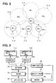
- the communication system S1 performs high-speed communication in narrow cells 1-1,1-2,1-3,1-4, etc. which are allocated in spot-wise fashion as shown in Fig. 2, while the communication system S2 performs relatively low speed communication in wide cells 2-1,2-2,2-3,2-4 2-5,2-6, etc. which are allocated in overcast fashion.
- the communication system S1 has base stations BS1-1, BS1-2, BS1-3, etc. which belong to the same sub-network (sub-network) SN1.
- the sub-network SN1 is connected to the Internet IN by way of a gateway GW1.
- the communication system S2 has base stations BS2-1, BS2-2, BS2-3, etc. which belong to the same sub-network (sub-network) SN2.
- the sub-network SN2 is connected to the Internet IN by way of a gateway GW2.
- a mobile terminal 20 makes access to a server SV via the Internet IN by using one of the communication systems S1 and S2.
- the mobile terminal 20 is designed to perform communication by using one of the communication systems S1 and S2 based on the provision of a mobile station network interface MS1 which can access the communication system S1 and a mobile station network interface MS2 which can access the communication system S2.
- the mobile station network interface MS1 makes access by using the IP (Internet IN) address of the sub-network SN1.
- the mobile station network interface MS2 makes access by using the IP address of the sub-network SN2.
- the mobile terminal 20 which communicates with one of the base stations BS1-1, BS1-2, BS1-3, etc. by using the communication system S1 and with one of the base stations BS2-1, BS2-2, BS2-3, etc by using the communication system S2, has its communication partner in each communication system determined by roaming.
- Roaming is the scheme of handing over communication among different base stations within the same communication system.
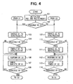
- Fig. 3 shows the specific arrangement of the mobile terminal 20.
- the mobile terminal 20 is made up of communication units 21a and 21b which are the mobile station network interfaces MS1 and MS2 mentioned above, line interfaces 22a and 22b which transact signals between the communication units 21a and 21b and the functional sections in the mobile terminal 20, a communication system switching unit 23, a network driver 24, an application unit 25, a receiving power monitor 26, a communication quality checking unit 27, and a control unit 28.
- the functional sections of the mobile terminal 20 are shown by blocks in the figure, these sections excluding the inherent hardware devices can be accomplished by means of a computer.
- the communication system switching unit 23 operates based on the standby/send-receive switching signal from the control unit 28 to bring each of the communication units 21a and 21b into the send/receive-enabled state (active state) or the standby state (inactive state) by way of the interfaces 22a and 22b.
- the communication unit can receive but cannot send information for example.
- the send/receive-enabled state of the communication unit 21a or 21b is the send/receive-enabled state of the communication system S1 or 2
- the standby state of the communication unit 21a or 21b is the standby state of the communication system S1 or S2.
- the receiving power monitor 26 detects the receiving power of the communication units 21a and 21b, i.e., the receiving power of the communication systems S1 and S2, by way of the interfaces 22a and 22b.
- the communication quality checking unit 27 assesses the communication quality of the communication unit which is in use currently among the communication units 21a and 21b.
- the checking of communication quality can be in terms of bit error rate (BER) for example.
- the application unit 25 has various application software for running the Web browser, electronic mail, etc., so that communication takes place based on these application software. In this case, information indicative of the mode of communication, i.e., sending or receiving, is notified to the control unit 28.
- the control unit 28 controls to bring one of the communication systems S1 and S2 into the send/receive-enabled state and the other into the standby state in response to the output signal of the receiving power monitor 26 and the output signal of the communication quality checking unit 27.
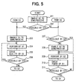
- Fig. 4 shows the control processing.
- control unit 28 executes the initializing processing to bring the communication systems S1 and S2 into the standby state (step 101). Next, it determines as to whether or not communication by use of the communication system S1 is possible based on the receiving power of the communication system S1 detected by the receiving power monitor 26 (step 102).
- the mobile terminal 20 In case the mobile terminal 20 is located in any of the narrow cells 1-1,1-2,1-3,1-4, etc. and communication by use of the communication system S1 is possible, it brings the communication system S1 into the send/receive-enabled state (step 103).
- step 104 determines as to whether or not the communication system S2 is in the send/receive-enabled state.
- the communication system S2 is in the standby state by the initializing processing, and the result of determination is "NO" .
- the control unit 28 brings the communication system S2 into the standby state (step 105).
- the control unit 28 controls the network driver 24 so as to perform communication by using the communication system S1 (step 106). It checks communication quality by the communication quality checking unit 27 during the communication by use of the communication system S1 (step 107), and determines based on the checking of communication quality as to whether or not communication by use of the communication system S1 can be maintained (step 108). In case communication by use of the communication system S1 is possible, it repeats the processing from step 106 to step 108.
- the mobile terminal 20 moves off the narrow cell where it has been located and communication by use of the communication system S1 can no longer be maintained, it brings the communication system S2 into the send/receive-enabled state (step 109).
- the communication system S1 In case the communication system S1 is in the send/receive-enabled state ("YES" at step 110), it brings the communication system S1 into the standby state (step 111). Subsequently, it controls the network driver 24 so as to perform communication by using the communication system S2 (step 112). It checks receiving power from receiving power monitor 26 by using the communication system S1 (step 113), and determines based on the receiving power as to whether or not communication by use of the communication system S1 can be started (step 114). In case communication by use of the communication system S1 cannot be started, it repeats the processing from step 112 to step 114.
- the control unit 28 determines that communication by use of the communication system S1 can be started, it proceeds to the foregoing step 103 thereby to perform communication by using the communication system S1.
- a high-speed communication system is used with high priority thereby to enhance the overall transmission efficiency and unused communication systems are brought to the standby state so that the power consumption is reduced.
- control unit 28 implements the initializing processing to bring the communication system S2 into the send/receive-enabled state (step 201). Next, it determines as to whether or not communication by use of the communication system S1 is possible based on the receiving power of the communication system S1 detected by the receiving power monitor 26 (step 202).
- step 203 In case communication by use of the communication system S1 is possible, it brings the communication system S1 into the send/receive-enabled state (step 203).
- the control unit 28 controls the network driver 24 so as to perform communication by using the communication system S1 (step 204). It checks communication quality by the communication quality checking unit 27 during the communication by use of the communication system S1 (step 205). It determines based on the checking of communication quality as to whether or not communication by use of the communication system S1 can be maintained (step 206). In case communication by use of the communication system S1 is possible, it repeats the processing from step 204 to step 206.
- the control unit 28 determines as to whether or not the communication system S2 is in the send/receive-enabled state (step 207). This is for the checking of linkage of the communication system S2 which can possibly enter the outside of wide cell temporarily and can be cut off. If the communication system S2 is not in the send/receive-enabled state, the control unit 28 brings the communication system S2 into the send/receive-enabled state (step 208).
- the control unit 28 controls the network driver 24 so as to perform communication by using the communication system S2 (step 209). It checks receiving power from receiving power monitor 26 by using the communication system S1 (step 210). It determines based on the receiving power as to whether or not communication by use of the communication system S1 can be started (step 211). In case communication by use of the communication system S1 cannot be started, it repeats the processing from step 209 to step 211.
- control unit 28 determines that communication by use of the communication system S1 can be started, it proceeds to the foregoing step 203 thereby to perform communication by using the communication system S1.
- the communication system S2 which can perform communication in a wide cell of wide service area, is kept active as backup system. Consequently momentary interruption of communication at an event of switching of communication systems can be prevented.
- this embodiment enables the mobile terminal 20, wherever it may move, to perform communication based on the selection of the fastest communication system available at the immediate location. Providing the communication systems with individual sub-networks facilitates the routing of communication with the mobile terminal 20.
- the up-link communication from the mobile terminal 20 to the server SV can take place as usual since the use of which communication system is known by the mobile terminal 20.
- the down-link communication from the server SV to the mobile terminal 20 necessitates the routing to determine which of the communication systems S1 and S2 be used.
- this embodiment uses the technique of mobile IP.
- a home agent HA is installed in the gateway GW1 of the sub-network SN1 to which the communication system S1 belongs, and a foreign agent FA is installed in the gateway GW2 of the sub-network SN2 of the communication system S2.
- access is made by using a home address.
- access is made by using a care-of address determined by the foreign agent FA.
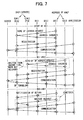
- Fig. 7 and Fig. 8 show the transaction of signals in this case.
- This embodiment is based on the assumption that both gateways GW1 and GW2 also function as DHCP (Dynamic Host Configuration Protocol) server SVs.
- DHCP Dynamic Host Configuration Protocol
- Fig. 7 shows the case where the mobile terminal 20 at the time of starting can use the communication system S1.
- the mobile terminal 20 requests the home agent HA by using the communication system S1 to issue a home IP address.
- the gateway GW1 which also functions as DHCP server SV, responds to the request to issue a home IP address to the mobile terminal 20.
- the mobile terminal 20 registers the home address in the home agent HA.
- the mobile terminal 20 can communicate with the server SV for both the up-link and down-link by using the home address. In this case, communication takes place based on the application software.
- the mobile terminal 20 When the mobile terminal 20 becomes to have communication by switching from the communication system S1 to the communication system S2, it requests the foreign agent FA by using the communication system S2 to issue a care-of address.
- the gateway GW2 which also functions as DHCP server SV, responds to the request to issue a care-of IP address to the mobile terminal 20.
- the mobile terminal 20 registers the care-of IP address in the home agent HA. In this case, the care-of IP address is transferred from the foreign agent FA to the home agent HA via the Internet IN. After that, the mobile terminal 20 can communicate on the up-link with the server SV by using the home address.
- the server SV For the down-link, the server SV makes transmission to the home agent HA via the Internet IN by using the home address, the home agent HA makes transmission by using the care-of IP address to the foreign agent FA via the Internet IN.
- the foreign agent FA makes transmission to the mobile terminal 20 via the base station BS2. Accordingly, for the down-link, the server SV makes transmission to the mobile terminal 20 based on the IP tunneling of the home agent HA and foreign agent FA.
- the mobile terminal 20 when the mobile terminal 20 has communication by switching from the communication system S1 to the communication system S2, it indicates the return to the home segment (communication by use of the communication system S1) to the home agent HA by using the communication system S1.
- the IP address which is no more used may be released (given back). This scheme fosters the efficient use of the IP address space.
- the IP address is released, however, it is necessary to get the above care-of IP address again at the time of switching to the communication system S2. However, in case the IP address is not released, it is not necessary to get the care-of IP address again.
- the mobile terminal 20 can communicate with the server SV by using the home address for both the up-link and down-link.
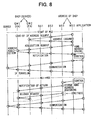
- Fig. 8 shows the case where the mobile terminal 20 at the time of starting cannot use the communication system S1.
- the mobile terminal 20 requests the foreign agent FA by using the communication system S2 to issue a care-of IP address.
- the foreign agent FA responds to the request to issue a care-of IP address to the mobile terminal 20.
- the mobile terminal 20 requests to have a home address. This request is sent from the foreign agent FA to the home agent HA via the Internet IN, and a home address is acquired.
- the home address is notified from the home agent HA to the mobile terminal 20 via the foreign agent FA and via the base station BS2.
- the mobile terminal 20 saves the acquired home address by using the control program.
- the mobile terminal 20 makes transmission on the up-link to the server SV by using the home address, and the server SV makes transmission on the down-link to the mobile terminal 20 by using the IP tunneling of the foreign agent FA.
- the mobile terminal 20 When the mobile terminal 20 becomes to have communication by switching from the communication system S1 to the communication system S2, it uses the home address, which has been saved by the control program, to notify from the communication system S1 to the home agent HA the return to the home segment. In this case, the IP address which is no more used may be released. After that, the mobile terminal 20 can communicate with the server SV by using the home address on both the up-link and down-link as described above.
- a home agent HA is installed in the sub-network to which the communication system of the highest communication speed belongs, and foreign agents FA are installed in sub-networks to which other communication systems belong.
- gateways GW1 and GW2 function also as DHCP server SVs and that the mobile terminal 20 checks temporarily IP addresses used for the mobile station network interfaces MS1 and MS2 from the DHCP server SVs, it is possible to foster the efficient use of the IP address space and eliminate the task of address issuance.
- An alternative scheme is to use fixed addresses for the communication systems S1 and S2 and give the addresses to the mobile terminal 20 in advance. This scheme eliminates the time expenditure of address issuance and enables smooth switching of communication systems.
- Fig. 9 shows the arrangement of the mobile terminal which is used for the wireless communication system of a second embodiment.
- the mobile terminal 20 is assumed to have a navigation system.
- a vehicle driver should drive a vehicle along the guided route. Accordingly, in the case of movement along the guided route, it is possible to know in advance the order of switching of communication systems. This processing enables smooth switching of communication systems.
- the mobile terminal 20 of this embodiment includes a navigation system 29 and a storage medium 30 for storing cell position information as shown in Fig. 9. It operates to switch communication systems by using these devices.
- the remaining portion of Fig. 9 is identical to the first embodiment.
- the navigation system 29 releases the present location of the mobile terminal 20 and route information in the case of route guidance to the control unit 28.
- the storage medium 30 stores cell position information indicative of the positions and ranges (e.g., center coordinates of circles and radiuses) of individual narrow cells 1-1,1-2, 1-3,1-4, etc. and wide cells 2-1,2-2,2-3,2-4 2-5,2-6, etc. shown in Fig. 2.
- the navigation system 29, in the case of performing route guide, sets a route from the present location to the destination as shown in Fig. 10.
- the control unit 28 checks the route information from the navigation system 29 and determines the switching positions of communication systems on the route, e.g., positions a through h in Fig. 10, based on the cell position information stored in the storage medium 30, thereby making a switching table as shown in Fig. 11.
- the switching table shown in Fig. 10 indicates the switching between the communication system S1 and communication system S2 at positions b, c, d, e, g and h.
- Fig. 12 shows the control processing of this second embodiment.
- the control unit 28 Prior to the control processing, the control unit 28 makes a switching table as shown in Fig. 11 by making reference to the cell position information in the storage medium 30 based on the route information provided by the navigation system 29.
- the control unit 28 starts the control processing shown in Fig. 12, and checks information of the present location from the navigation system 29 (step 301). It determines based on the switching table as to whether or not the cell in use is an object cell of the communication system S1 (step 302). If the cell in use is an object of the communication system S1, it brings the communication system S1 into the send/receive-enabled state (step 303).
- step 304 it determines as to whether or not communication by use of the communication system S1 is possible based on the receiving power of the communication system S1 detected by the receiving power monitor 26 (step 304). In case communication by use of the communication system S1 is possible, it determines as to whether or not the communication system S2 is in the send/receive-enabled state (step 305). If the communication system S2 is in the send/receive-enabled state, it brings the communication system S2 into the standby state (step 306).
- the control unit 28 controls the network driver 24 so as to perform communication by using the communication system S1 (step 307). It checks communication quality by the communication quality checking unit 27 during the communication by use of the communication system S1 (step 308). It determines based on the checking of communication quality as to whether or not communication by use of the communication system S1 can be maintained (step 309). In case communication by use of the communication system S1 is possible, it checks information of the present location from the navigation system 29 (step 310). It determines based on the switching table as to whether or not the present location is close to the switching position to the communication system S2, i.e., whether or not the present location is within a certain distance from the switching position (step 311). Unless the present location is close to the switching position to the communication system S2, it repeats the processing of step 307 through step 312.
- the present location In case the present location is close to the switching position to the communication system S2, it brings the communication system S2 into the send/receive-enabled state (step 312). It determines as to whether or not the communication system S1 is in the send/receive-enabled state (step 313). If the communication system S1 is in the send/receive-enabled state, it brings the communication system S1 into the standby state (step 314).
- the control unit 28 controls the network driver 24 so as to perform communication by using the communication system S2 (step 315).
- it checks information of the present location from the navigation system 29 (step 316). It determines based on the switching table as to whether or not the present location is close to the switching position to the communication system S1 (step 317). Unless the present location is close to the switching position to the communication system S1, it repeats the processing of step 315 through step 317. In case the present location is close to the switching position to the communication system S1, it proceeds to the foregoing step 303 to perform communication by using the communication system S1.
- the control unit 28 corrects the cell position information and proceeds to communication by use of the communication system S2. That is, if cell position information is not necessarily correct, the mobile terminal 20 checks the information and modifies the cell position information by learning if it is erroneous.
- an alternative scheme is to get only information of the present location from the navigation system 29 and determine the communication system to be used from the present location and cell position information.
- This embodiment can also be applied to the case of three or more communication systems as in the case of the first embodiment.
- Fig. 13 shows a wireless communication system designed to switch communication systems between the mobile terminal 20 and the server SV by using routers.
- the gateways GW1 and GW2 also function as routers, and the mobile terminal 20 switches the connection between the communication systems S1 and S2 and the application unit 25 by using a router 31.
- the remaining portion of Fig. 13 is identical to the first embodiment.
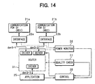
- Fig. 14 shows the specific arrangement of the mobile terminal 20.
- the router 31 is used in place of the communication system switching unit 23 shown in Fig. 3.
- the router 31 can be accomplished on a software basis.
- the router 31 selectively connects the driver dev3-1 for the interface 22a of the communication system S1 or the driver dev3-2 for the interface 22b of the communication system S2 to the driver dev3-3 for the application unit 25.
- the routers of the gateways GW1 and GW2 and the router of the mobile terminal 20 implement the routing by using routing tables.
- Fig. 16 shows the provision of routing tables R1 and R2 for the gateways GW1 and GW2, respectively, and a routing table R3 for the router. These routing tables R1-R3 have their contents revised depending on which of the communication systems S1 and S2 be used for communication.
- Fig. 16A shows an example of the routing tables R1-R3 in the case of communication by use of the communication system S1.
- Fig. 16B shows an example of the routing tables R1-R3 in the case of communication by use of the communication system S2.
- the routing table R1 of the gateway GW1 is given dev1-1 for sub-network SN1 and for sub-network 3 (section where application software runs) and dev1-0 for the other.
- the routing table R2 of the gateway GW2 is given dev2-2 for sub-network SN2 and dev2-0 for the other.
- the routing table R3 in the mobile terminal 20 is given dev3-3 for sub-network 3 and dev3-1 for the other.
- the server SV releases data to dev1-1 since sub-network 3 is contained in the routing table R1 of the gateway GW1.
- the released data is transmitted from any base station BS1 (BS1-2 in Fig. 15) of the communication system S1 to the mobile terminal 20.
- the mobile terminal 20 receives the transmitted signal by using the communication system S1.
- the router 31 has sub-network 3 in the routing table R3, and the received signal from the communication system S1 is fed to dev3-3.
- the application unit 25 designates "other"
- data from the application unit 25 is fed to dev3-1 and then data is sent from the communication system S1 to the gateway GW1 by way of any base station BS1 (BS1-2 in Fig. 15) of the communication system S1.
- the gateway GW1 makes reference to the routing table R1 to release the received data to dev1-0, and it is transmitted to the server SV.
- routing of the down-link and up-link takes place by use of the routing tables R1-R3 shown in Fig. 16B in the same manner as explained above.
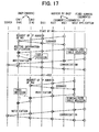
- Fig. 17 shows the transaction of signals when the routing tables R1-R3 are revised.
- the mobile terminal 20 requests the IP address of the communication system S1 to the gateway GW1 by using the communication system S1. Since the gateway GW1 also functions as DHCP server SV, as in the case of the first embodiment, it responds to the IP address request to issue the IP address of the communication system S1 to the mobile terminal 20. Then, the mobile terminal 20 revises the routing table R3 as shown in Fig. 16B.
- the mobile terminal 20 notifies routing information (command of altering the routing tables R1 and R2 as shown in Fig. 16A) to the gateway GW1 by using the communication system S1.
- This routing information is further transferred from the gateway GW1 to the gateway GW2 via the Internet IN.
- the gateways GW1 and GW2 revise the routing tables R1 and R2 based on the routing information as shown in Fig. 16A.
- communication with the server SV can take place based on the application software.
- the mobile terminal 20 When the mobile terminal 20 becomes to have communication by switching from the communication system S1 to the communication system S2, it requests the IP address of the MS2 to the gateway GW2 by using the communication system S2. Since the gateway GW2 also functions as the DHCP server SV, as in the case of the first embodiment, it responds to the IP address request to issue the IP address of the MS2 to the mobile terminal 20. Then, the mobile terminal 20 revises the routing table R3 accordingly as shown in Fig. 16B.
- the mobile terminal 20 indicates routing information (command of altering the routing tables R1 and R2 as shown in Fig. 16B) to the gateway GW2 by using the communication system S2.
- This routing information is further transferred from the gateway GW2 to the gateway GW1 via the Internet IN.
- the gateways GW1 and GW2 revise the routing tables R1 and R2 based on the routing information as shown in Fig. 16B.
- communication with the server SV can take place based on the application software.
- the router 31 is placed between the communication systems S1 and S2 and the section where the application software runs, with the application software having a specific sub-network (sub-network SN3) address, and then communication with a same caller's address can take place.
- sub-network SN3 sub-network
- the data communication route can be selected from among the communication systems S1 and S2 based on the rewriting of the routing tables R1-R3, and switching of communication systems can take place smoothly.
- the control unit 28 of this embodiment implements the same control processing as the first and second embodiments except for the rewriting of the routing tables as described above. Specifically, the part of processing for performing communication by use of the communication systems S1 and S2 in the first and second embodiments is replaced with the processing of rewriting the routing tables R1-R3.
- the router 31 may be of a different arrangement, provided that it is a switching means having the router function.
- This embodiment can also be applied to the case of three or more communication systems as in the cases of the first and second embodiments.
- each section of the mobile terminal is understood to be a means of accomplishing its intended function.
Landscapes
- Engineering & Computer Science (AREA)
- Computer Networks & Wireless Communication (AREA)
- Signal Processing (AREA)
- Computer Security & Cryptography (AREA)
- Mobile Radio Communication Systems (AREA)
- Data Exchanges In Wide-Area Networks (AREA)
Abstract
Description
Claims (17)
- A wireless system comprising:a mobile terminal (20); anda plurality of communication systems (S1, S2) for communication with the mobile terminal, the systems being different from each other, characterized in thatthe communication systems (S1, S2) each have base stations (BS1, BS2) belonging to a sub-network (SN1, SN2) which is unique to the communication system, each sub-network being connected to an Internet (IN) by way of a gateway (GW1, GW2) provided for the sub-network, andthe mobile terminal (20) has a plurality of mobile station network interfaces (MS1, MS2) which can access the communication systems respectively, and means (23, 27, 28) of switching communication systems accessed by the mobile station network interfaces depending on the communication quality of the communication systems.
- A wireless system comprising:a mobile terminal (20); anda plurality of communication systems (S1, S2) for communication with the mobile terminal, the systems being different from each other, characterized in thateach of the communication systems (S1, S2) has base stations (BS1, BS2) belonging to a sub-network (SN1, SN2) which is unique to the communication system, each sub-network being connected to an Internet (IN) by way of a gateway (GW1, GW2) provided for the sub-network, andthe mobile terminal (20) has a plurality of mobile station network interfaces (22a, 22b) which can access the communication systems respectively, and means (23, 28-30) of switching the communication systems accessed by the mobile station network interfaces based on cell position information of cells which are formed by the base stations of the communication systems and the present location of the mobile terminal and depending on the cell at the present location.
- The wireless system as in claim 2, further characterized in that:the communication system switching means (23, 28-30) sets switching positions of the communication systems based on the cell position information and route information in a case of implementation of route guidance of the mobile terminal by means of a navigation system (29), and carries out switching depending on a relation between the switching positions and the present location.
- The wireless system according to any one of claims 1 through 3, further characterized in that:one of the sub-networks (SN1, SN2) has a home agent (HA) and another of the sub-networks (SN1, SN2) has a foreign agent (FA); andthe mobile terminal (20) makes access by using a home address in a case of communication with the base station which belongs to the one of sub-networks or makes access by using a care-of address determined by the foreign agent in a case of communication with the base station which belongs to the another of the sub-networks.
- The wireless system as in claim 4, further characterized in that:the base station which belongs to the one of sub-networks communicates with the mobile terminal faster than the base station which belongs to the another of sub-networks.
- A network comprising:a mobile terminal (20); anda plurality of base stations (BS1, BS2) each of which communicates with the mobile terminal by using a communication system among a plurality of communication systems (S1, S2) which are different from each other, characterized in thata plurality of sub-networks (SN1, SN2) are arranged so that one of the base stations, which communicates with the mobile terminal by using a same communication system belong to a same sub-network, andthe sub-networks (SN1, SN2) are each connected to an Internet (IN) by way of gateways (GW1, GW2) which are positioned for the sub-networks.
- The wireless system as in claim 1, further characterized by comprising:wherein the means (23, 27, 28) switches the communication systems accessed by the mobile station network interfaces depending on the communication quality of the communication systems.a plurality of mobile station network interfaces (22a, 22b) which can access the communication systems respectively,
- The wireless system as in claim 1, further characterized by comprising:wherein the (23, 27, 28) switches the communication systems accessed by the mobile station network interfaces based on cell position information of cells which are formed by the base stations of the communication systems and present location of the mobile terminal and depending on the cell at the present location.a plurality of mobile station network interfaces (22a, 22b) which access the communication systems, respectively,
- The wireless system as in claim 8, further characterized in that:the means (23, 27, 28) sets the switching positions of the communication systems based on the cell position information and route information in a case of implementation of route guidance of the mobile terminal by means of a navigation system (29), and carries out switching depending on a relation between the switching positions and the present location.
- The wireless system as in claim 9, further characterized by comprising:means for modifying the cell position information upon determining before switching at a next switching position that communication by use of the communication system which is in use currently cannot be maintained.
- The wireless system as in any one of claims 8 through 10, further characterized by comprising:means which, if communication by use of a high-speed communication system which is highest in communication speed among the communication systems is possible, brings the mobile station network interface for the communication by use of the high-speed communication system into a send/receive-enabled state and other mobile station network interfaces into a standby state, and if communication by use of the high-speed communication system cannot be maintained, brings the mobile station network interface for the communication by use of the high-speed communication system into the standby state and any other mobile station network interface into the send/receive-enabled state.
- The wireless system as in any one of claims 8 through 10, further characterized in that:the mobile station network interfaces (22a, 22b) are all brought into the send/receive-enabled state, and, if communication by use of the high-speed communication system which is highest in communication speed among the communication systems is possible, communication is performed by using the high-speed communication system, and if communication by use of the high-speed communication system cannot be maintained, communication is performed by using a communication system which is wider in service area than the high-speed communication system.
- The wireless system as in any one of claims 8 through claim 12, further characterized in that:the mobile station network interfaces (22a, 22b) make access by using IP addresses which are given temporarily by a server (SV) in the sub-networks which belong to the communication systems.
- The wireless system as in any one of claims 8 through 12, further characterized in that:the mobile station networks make access by using fixed IP addresses.
- A wireless system comprising:a mobile terminal (20); anda plurality of communication systems (S1, S2) for communication with the mobile terminal, the systems being different from each other, characterized in thatthe communication systems (S1, S2) each have base stations (BS1, BS2) belonging to a sub-network (SN1, SN2) which is unique to the communication system, each sub-network being connected to an Internet (IN) by way of a gateway (GW1, GW2) provided for the sub-network, the gateway having a router function for routing between the internet and the sub-network, andthe mobile terminal (20) has a plurality of mobile station network interfaces (22a, 22b) which can access the communication systems respectively, and means (31) having the router function located between the mobile station network interfaces and a section of running application software (25), thereby switching the communication systems by connecting the application software running section to any one of the mobile station network interfaces.
- The wireless communication system as in claim 15, further characterized in that:each of the gateways (GW1, GW2) and the means (28, 31) have routing tables used for the routing, thereby switching the communication systems by revising contents of the respective routing tables.
- The wireless system as in claim 16, further characterized in that:each of the gateways (GW1, GW2) revises the routing table in response to a command from the mobile terminal.
Applications Claiming Priority (2)
| Application Number | Priority Date | Filing Date | Title |
|---|---|---|---|
| JP2000391124A JP3580250B2 (en) | 2000-12-22 | 2000-12-22 | Wireless communication system, network and mobile terminal used in wireless communication system |
| JP2000391124 | 2000-12-22 |
Publications (3)
| Publication Number | Publication Date |
|---|---|
| EP1217791A2 true EP1217791A2 (en) | 2002-06-26 |
| EP1217791A3 EP1217791A3 (en) | 2004-01-02 |
| EP1217791B1 EP1217791B1 (en) | 2008-08-27 |
Family
ID=18857338
Family Applications (1)
| Application Number | Title | Priority Date | Filing Date |
|---|---|---|---|
| EP20010129881 Expired - Lifetime EP1217791B1 (en) | 2000-12-22 | 2001-12-14 | Wireless communication system having communication system switching function |
Country Status (4)
| Country | Link |
|---|---|
| US (1) | US7209465B2 (en) |
| EP (1) | EP1217791B1 (en) |
| JP (1) | JP3580250B2 (en) |
| DE (1) | DE60135536D1 (en) |
Cited By (2)
| Publication number | Priority date | Publication date | Assignee | Title |
|---|---|---|---|---|
| KR100795061B1 (en) | 2006-06-13 | 2008-01-17 | 강릉대학교산학협력단 | Communication service method and terminal accordingly |
| EP2362601B1 (en) * | 2003-01-27 | 2019-10-23 | Qualcomm Incorporated(1/3) | Seamless roaming |
Families Citing this family (39)
| Publication number | Priority date | Publication date | Assignee | Title |
|---|---|---|---|---|
| JP3580250B2 (en) * | 2000-12-22 | 2004-10-20 | 株式会社デンソー | Wireless communication system, network and mobile terminal used in wireless communication system |
| JPWO2003041341A1 (en) * | 2001-11-05 | 2005-03-03 | 松下電器産業株式会社 | Server device and terminal device used in video transmission system |
| US7236475B2 (en) * | 2002-02-06 | 2007-06-26 | Ntt Docomo, Inc. | Using subnet relations to conserve power in a wireless communication device |
| US20030233453A1 (en) * | 2002-06-18 | 2003-12-18 | Institute For Information Industry | Topology probing method for mobile IP system |
| KR100625654B1 (en) * | 2002-08-29 | 2006-09-20 | 에스케이 텔레콤주식회사 | A method for determining access system based on WLAN signal strength in wireless local area network / mobile phone interworking system and mobile terminal for same |
| US7219367B2 (en) * | 2002-09-09 | 2007-05-15 | Scientific-Atlanta, Inc. | Backup communication modes |
| US7376097B2 (en) * | 2002-11-27 | 2008-05-20 | Ntt Docomo Inc. | Method of associating an IP address with a plurality of link layer addresses in a wireless communication network |
| KR100542119B1 (en) | 2002-12-12 | 2006-01-11 | 한국전자통신연구원 | Wireless LAN auto discovery method and terminal performing the method |
| JP2004208001A (en) | 2002-12-25 | 2004-07-22 | Sharp Corp | Wireless communication system, wireless communication method, wireless communication program, and program recording medium |
| JP4552449B2 (en) * | 2003-02-20 | 2010-09-29 | パナソニック株式会社 | Mobile router device, mobile network system, and mobility management method for mobile router device |
| JP2004260444A (en) | 2003-02-25 | 2004-09-16 | Ntt Docomo Inc | Handover control system and method, mobile terminal, handover control device |
| TWI353753B (en) * | 2003-03-27 | 2011-12-01 | Lenovo Singapore Pte Ltd | Access to a wireless local area network |
| KR100955759B1 (en) | 2003-03-31 | 2010-04-30 | 주식회사 케이티 | Wireless Internet Service Method in Wireless Internet Service System with Various Service Areas |
| US6987985B2 (en) * | 2003-06-06 | 2006-01-17 | Interdigital Technology Corporation | Wireless communication components and methods for multiple system communications |
| US7978655B2 (en) * | 2003-07-22 | 2011-07-12 | Toshiba America Research Inc. | Secure and seamless WAN-LAN roaming |
| JP3960963B2 (en) | 2003-10-29 | 2007-08-15 | 京セラ株式会社 | Mobile communication terminal, mobile communication management apparatus, mobile communication system, mobile communication terminal program, mobile communication management program, and mobile communication method |
| CN1898660B (en) | 2003-12-01 | 2014-06-25 | 美商内数位科技公司 | User Initiated Handover Based on Session Initiation Protocol |
| JP4529462B2 (en) * | 2004-02-09 | 2010-08-25 | Kddi株式会社 | Communication terminal, communication terminal program, and communication interface switching method |
| JP4568557B2 (en) * | 2004-08-10 | 2010-10-27 | 株式会社エヌ・ティ・ティ・ドコモ | Mobile communication system and mobile station |
| WO2006048941A1 (en) * | 2004-11-05 | 2006-05-11 | Matsushita Electric Industrial Co., Ltd. | Mobile communication terminal apparatus, control method thereof, communication system, and loaming method thereof |
| US20060146794A1 (en) * | 2004-12-30 | 2006-07-06 | Motorola, Inc. | Peer network interaction facilitation method |
| US7881280B2 (en) * | 2004-12-30 | 2011-02-01 | Motorola Mobilty, Inc. | Method and apparatus to facilitate a non-fully meshed communications system gateway interface |
| JP2006217327A (en) * | 2005-02-04 | 2006-08-17 | Kddi Corp | Wireless communication apparatus and communication system |
| KR100691505B1 (en) * | 2005-05-20 | 2007-03-09 | 한국전자통신연구원 | Communication mode control method of multi-mode terminal and multi-mode terminal |
| JP4508051B2 (en) * | 2005-09-06 | 2010-07-21 | Kddi株式会社 | Mobile device and program |
| JP4694356B2 (en) * | 2005-11-22 | 2011-06-08 | 株式会社日立製作所 | Wireless terminal having wireless telephone function and IP telephone function, and roaming method between public wireless line and wireless LAN |
| JP4577222B2 (en) * | 2006-01-20 | 2010-11-10 | 株式会社デンソー | Mobile communication system, radio base station, and distribution method |
| EP1841142A1 (en) * | 2006-03-27 | 2007-10-03 | Matsushita Electric Industries Co., Ltd. | Sleep-state and service initiation for mobile terminal |
| US8135782B2 (en) | 2006-11-22 | 2012-03-13 | Casio Hitachi Mobile Communications Co., Ltd. | Electronic apparatus, presence communication system, and computer-readable recording medium |
| JP2008236381A (en) * | 2007-03-20 | 2008-10-02 | Toshiba Corp | Mobile communication terminal device |
| KR100858767B1 (en) * | 2007-05-04 | 2008-09-16 | 마쓰시타 일렉트릭 인더스트리얼 코우.,엘티디. | Mobile communication terminal device, control method thereof, communication system and grombling method |
| JP2007336581A (en) * | 2007-08-03 | 2007-12-27 | Ntt Docomo Inc | HANDOVER CONTROL SYSTEM AND METHOD, MOBILE TERMINAL, HANDOVER CONTROL DEVICE |
| JP5098533B2 (en) * | 2007-09-14 | 2012-12-12 | 日本電気株式会社 | Road-to-vehicle communication system, road-to-vehicle communication method, road-to-vehicle communication program, and program recording medium |
| JP4634480B2 (en) * | 2008-03-31 | 2011-02-16 | 株式会社日立製作所 | Wireless communication system, terminal device and control node device |
| JP4667493B2 (en) * | 2008-08-09 | 2011-04-13 | 京セラ株式会社 | Mobile communication terminal |
| US8320346B2 (en) * | 2009-09-25 | 2012-11-27 | Intel Corporation | Apparatus and methods for universal services interface networking |
| JP5470590B2 (en) | 2011-04-14 | 2014-04-16 | 株式会社日立製作所 | Communication apparatus and handover control method |
| EP2717520B1 (en) * | 2011-05-30 | 2016-03-02 | NEC Corporation | Communication path control system, and communication path control method |
| JP7785151B1 (en) * | 2024-11-15 | 2025-12-12 | Kddi株式会社 | Information processing device, information processing method, and program |
Family Cites Families (23)
| Publication number | Priority date | Publication date | Assignee | Title |
|---|---|---|---|---|
| JPH04242353A (en) | 1991-01-16 | 1992-08-31 | Sony Corp | Radio communication terminal equipment |
| US20040264402A9 (en) * | 1995-06-01 | 2004-12-30 | Padcom. Inc. | Port routing functionality |
| FI105746B (en) * | 1995-09-29 | 2000-09-29 | Nokia Mobile Phones Ltd | Integrated radio communication system |
| US6185427B1 (en) * | 1996-09-06 | 2001-02-06 | Snaptrack, Inc. | Distributed satellite position system processing and application network |
| US6122263A (en) | 1997-06-10 | 2000-09-19 | Telefonaktiebolaget Lm Ericsson | Internet access for cellular networks |
| DE19730363B4 (en) * | 1997-07-15 | 2011-08-11 | Telefonaktiebolaget Lm Ericsson (Publ) | Site-specific World Wide Web services in digital cellular communication networks |
| US6278706B1 (en) | 1998-04-03 | 2001-08-21 | Opuswave Networks, Inc. | Wireless packet data communication apparatus and method |
| US6625135B1 (en) * | 1998-05-11 | 2003-09-23 | Cargenie Mellon University | Method and apparatus for incorporating environmental information for mobile communications |
| FI105978B (en) * | 1998-05-12 | 2000-10-31 | Nokia Mobile Phones Ltd | Method of connecting a wireless data terminal in a data transmission network and a wireless data terminal |
| US6320873B1 (en) | 1998-08-27 | 2001-11-20 | Qualcomm Incorporated | CDMA transmission of packet-switched data |
| JP2000175249A (en) | 1998-12-01 | 2000-06-23 | Denso Corp | In-vehicle communication device |
| US7239618B1 (en) | 1998-12-11 | 2007-07-03 | Lucent Technologies Inc. | Single phase local mobility scheme for wireless access to packet-based networks |
| US6763007B1 (en) | 1998-12-11 | 2004-07-13 | Lucent Technologies Inc. | Two phase local mobility scheme for wireless access to packet based networks |
| WO2000038465A1 (en) * | 1998-12-18 | 2000-06-29 | Telefonaktiebolaget Lm Ericsson (Publ) | Method and system for intersystem soft handoff |
| US6973057B1 (en) * | 1999-01-29 | 2005-12-06 | Telefonaktiebolaget L M Ericsson (Publ) | Public mobile data communications network |
| FI108832B (en) * | 1999-03-09 | 2002-03-28 | Nokia Corp | Optimization of IP path selection in an access network |
| JP3325541B2 (en) | 1999-04-30 | 2002-09-17 | 株式会社東芝 | Wireless communication system and wireless communication control method |
| GB9913102D0 (en) * | 1999-06-04 | 1999-08-04 | Nokia Telecommunications Oy | An element for a communications system |
| FI108983B (en) * | 1999-06-07 | 2002-04-30 | Nokia Corp | Lapsed by a mobility agent in an access network |
| US7327683B2 (en) * | 2000-03-16 | 2008-02-05 | Sri International | Method and apparatus for disseminating topology information and for discovering new neighboring nodes |
| FI20000662L (en) * | 2000-03-21 | 2001-09-22 | Nokia Oyj | Cell switching in a network supporting multiple relay technologies |
| ATE281047T1 (en) * | 2000-11-17 | 2004-11-15 | Ericsson Telefon Ab L M | MOBILE COMMUNICATION NETWORK |
| JP3580250B2 (en) * | 2000-12-22 | 2004-10-20 | 株式会社デンソー | Wireless communication system, network and mobile terminal used in wireless communication system |
-
2000
- 2000-12-22 JP JP2000391124A patent/JP3580250B2/en not_active Expired - Lifetime
-
2001
- 2001-12-14 EP EP20010129881 patent/EP1217791B1/en not_active Expired - Lifetime
- 2001-12-14 DE DE60135536T patent/DE60135536D1/en not_active Expired - Lifetime
- 2001-12-19 US US10/024,748 patent/US7209465B2/en not_active Expired - Lifetime
Cited By (2)
| Publication number | Priority date | Publication date | Assignee | Title |
|---|---|---|---|---|
| EP2362601B1 (en) * | 2003-01-27 | 2019-10-23 | Qualcomm Incorporated(1/3) | Seamless roaming |
| KR100795061B1 (en) | 2006-06-13 | 2008-01-17 | 강릉대학교산학협력단 | Communication service method and terminal accordingly |
Also Published As
| Publication number | Publication date |
|---|---|
| US20020080778A1 (en) | 2002-06-27 |
| JP3580250B2 (en) | 2004-10-20 |
| DE60135536D1 (en) | 2008-10-09 |
| EP1217791A3 (en) | 2004-01-02 |
| US7209465B2 (en) | 2007-04-24 |
| EP1217791B1 (en) | 2008-08-27 |
| JP2002199426A (en) | 2002-07-12 |
Similar Documents
| Publication | Publication Date | Title |
|---|---|---|
| EP1217791B1 (en) | Wireless communication system having communication system switching function | |
| US8155041B2 (en) | Method for handover between heterogeneous networks using link trigger signal in multi-interface mobile router | |
| KR100939852B1 (en) | Distributed infrastructure for wireless data communications | |
| EP1206098B1 (en) | Home agent and IP packet transferring method | |
| EP1281285B1 (en) | Apparatus and method for assigning temporary identifiers to a mobile node during handover | |
| KR100829655B1 (en) | Mobile IP for Mobile AD Hoc Network | |
| US7496084B2 (en) | Mobile node, a control method thereof, and a mobile node control program | |
| US20040184465A1 (en) | Mobile IP communication system using dual stack transition mechanism and method thereof | |
| US8223719B2 (en) | Apparatus for controlling handover between heterogeneous networks, method of performing handover between heterogeneous networks, and mobile router | |
| US20050078633A1 (en) | Wireless communication system and mobile terminal | |
| KR20030089719A (en) | Distributed infrastructure for wireless data communications | |
| EP1804443B1 (en) | Path control device and path control method | |
| US7519367B2 (en) | Handover control apparatus, radio terminal device, edge router, router, mobile communication system, and handover control method | |
| US7307967B2 (en) | Mobile communications system and routing management apparatus used in the mobile communications system | |
| US20020183089A1 (en) | Non-intrusive detection of enhanced capabilities at existing cellsites in a wireless data communication system | |
| JP2004304841A (en) | Radio communication system and mobile terminal used in radio communication system | |
| US20100118728A1 (en) | Navigation within a wireless network | |
| WO2005053250A1 (en) | Communication handover method, communication message processing method, program for executing these methods by use of computer, and communication system | |
| US20050201344A1 (en) | Mobile communication network system and a mobility managing unit | |
| US20080205393A1 (en) | System and Method for Routing Packets in Portable Internet System | |
| KR100938281B1 (en) | Handover Method between Heterogeneous Networks using Link Trigger Signal in Mobile Nodes with Multiple Interfaces | |
| US20080153489A1 (en) | Apparatus and method for reducing signaling overhead | |
| Comer et al. | An Architecture for A Camputs-Scale Wireless Mobile Internet | |
| JP2004274458A (en) | Handover control system between heterogeneous wireless systems, edge node used in the system, and mobile communication terminal | |
| US20100272016A1 (en) | Method for supporting transport network independent ip mobility in mobile terminal and system thereof |
Legal Events
| Date | Code | Title | Description |
|---|---|---|---|
| PUAI | Public reference made under article 153(3) epc to a published international application that has entered the european phase |
Free format text: ORIGINAL CODE: 0009012 |
|
| AK | Designated contracting states |
Kind code of ref document: A2 Designated state(s): AT BE CH CY DE DK ES FI FR GB GR IE IT LI LU MC NL PT SE TR |
|
| AX | Request for extension of the european patent |
Free format text: AL;LT;LV;MK;RO;SI |
|
| PUAL | Search report despatched |
Free format text: ORIGINAL CODE: 0009013 |
|
| AK | Designated contracting states |
Kind code of ref document: A3 Designated state(s): AT BE CH CY DE DK ES FI FR GB GR IE IT LI LU MC NL PT SE TR |
|
| AX | Request for extension of the european patent |
Extension state: AL LT LV MK RO SI |
|
| 17P | Request for examination filed |
Effective date: 20040628 |
|
| AKX | Designation fees paid |
Designated state(s): DE FR GB |
|
| 17Q | First examination report despatched |
Effective date: 20050801 |
|
| GRAP | Despatch of communication of intention to grant a patent |
Free format text: ORIGINAL CODE: EPIDOSNIGR1 |
|
| RIC1 | Information provided on ipc code assigned before grant |
Ipc: H04L 12/56 20060101AFI20080219BHEP Ipc: H04Q 7/38 20060101ALI20080219BHEP |
|
| GRAS | Grant fee paid |
Free format text: ORIGINAL CODE: EPIDOSNIGR3 |
|
| GRAA | (expected) grant |
Free format text: ORIGINAL CODE: 0009210 |
|
| AK | Designated contracting states |
Kind code of ref document: B1 Designated state(s): DE FR GB |
|
| REG | Reference to a national code |
Ref country code: GB Ref legal event code: FG4D |
|
| REF | Corresponds to: |
Ref document number: 60135536 Country of ref document: DE Date of ref document: 20081009 Kind code of ref document: P |
|
| REG | Reference to a national code |
Ref country code: GB Ref legal event code: 746 Effective date: 20090313 |
|
| PLBE | No opposition filed within time limit |
Free format text: ORIGINAL CODE: 0009261 |
|
| STAA | Information on the status of an ep patent application or granted ep patent |
Free format text: STATUS: NO OPPOSITION FILED WITHIN TIME LIMIT |
|
| 26N | No opposition filed |
Effective date: 20090528 |
|
| REG | Reference to a national code |
Ref country code: FR Ref legal event code: PLFP Year of fee payment: 15 |
|
| REG | Reference to a national code |
Ref country code: FR Ref legal event code: PLFP Year of fee payment: 16 |
|
| REG | Reference to a national code |
Ref country code: FR Ref legal event code: PLFP Year of fee payment: 17 |
|
| PGFP | Annual fee paid to national office [announced via postgrant information from national office to epo] |
Ref country code: FR Payment date: 20201223 Year of fee payment: 20 Ref country code: GB Payment date: 20201223 Year of fee payment: 20 Ref country code: DE Payment date: 20201211 Year of fee payment: 20 |
|
| REG | Reference to a national code |
Ref country code: DE Ref legal event code: R071 Ref document number: 60135536 Country of ref document: DE |
|
| REG | Reference to a national code |
Ref country code: GB Ref legal event code: PE20 Expiry date: 20211213 |
|
| PG25 | Lapsed in a contracting state [announced via postgrant information from national office to epo] |
Ref country code: GB Free format text: LAPSE BECAUSE OF EXPIRATION OF PROTECTION Effective date: 20211213 |