EP1217764A2 - Broadband raman amplifier - Google Patents
Broadband raman amplifier Download PDFInfo
- Publication number
- EP1217764A2 EP1217764A2 EP01310386A EP01310386A EP1217764A2 EP 1217764 A2 EP1217764 A2 EP 1217764A2 EP 01310386 A EP01310386 A EP 01310386A EP 01310386 A EP01310386 A EP 01310386A EP 1217764 A2 EP1217764 A2 EP 1217764A2
- Authority
- EP
- European Patent Office
- Prior art keywords
- pump
- amplifier
- wavelengths
- radiation
- wavelength
- Prior art date
- Legal status (The legal status is an assumption and is not a legal conclusion. Google has not performed a legal analysis and makes no representation as to the accuracy of the status listed.)
- Granted
Links
Images

Classifications
-
- H—ELECTRICITY
- H04—ELECTRIC COMMUNICATION TECHNIQUE
- H04B—TRANSMISSION
- H04B10/00—Transmission systems employing electromagnetic waves other than radio-waves, e.g. infrared, visible or ultraviolet light, or employing corpuscular radiation, e.g. quantum communication
- H04B10/29—Repeaters
- H04B10/291—Repeaters in which processing or amplification is carried out without conversion of the main signal from optical form
- H04B10/2912—Repeaters in which processing or amplification is carried out without conversion of the main signal from optical form characterised by the medium used for amplification or processing
- H04B10/2916—Repeaters in which processing or amplification is carried out without conversion of the main signal from optical form characterised by the medium used for amplification or processing using Raman or Brillouin amplifiers
-
- H—ELECTRICITY
- H01—ELECTRIC ELEMENTS
- H01S—DEVICES USING THE PROCESS OF LIGHT AMPLIFICATION BY STIMULATED EMISSION OF RADIATION [LASER] TO AMPLIFY OR GENERATE LIGHT; DEVICES USING STIMULATED EMISSION OF ELECTROMAGNETIC RADIATION IN WAVE RANGES OTHER THAN OPTICAL
- H01S3/00—Lasers, i.e. devices using stimulated emission of electromagnetic radiation in the infrared, visible or ultraviolet wave range
- H01S3/30—Lasers, i.e. devices using stimulated emission of electromagnetic radiation in the infrared, visible or ultraviolet wave range using scattering effects, e.g. stimulated Brillouin or Raman effects
- H01S3/302—Lasers, i.e. devices using stimulated emission of electromagnetic radiation in the infrared, visible or ultraviolet wave range using scattering effects, e.g. stimulated Brillouin or Raman effects in an optical fibre
Definitions
- the present invention relates to optical amplifiers and in particular to wide bandwidth optical amplifiers.
- the present invention is particularly applicable to Raman amplifiers.
- Raman amplification is considered to be particularly suitable for use in wideband and ultra wideband optical amplifiers, for example used in wavelength division multiplexing transmission systems.
- the reason for this is that, unlike Erbium doped fibre amplifiers, gain can be provided at a predetermined range of wavelengths by choosing a suitable pump wavelength.
- Raman amplification can be distributed along a transmission fibre, giving an improved optical signal-to-noise ratio, lower signal launch power and therefore longer transmission distances without requiring further amplification and/or repetition.
- the gain profile of the amplifier is far from flat.
- the gain profile will be a curve with a peak at the wavelength chosen for maximum amplification.
- FIG. 1 shows a prior art wideband Raman optical amplifier.
- a signal to be amplified is input to fibre 2.
- pump radiation is provided to fibre 2 through the signal and pump coupler 4.
- the resulting amplified signal is output on fibre 6.
- N different pump sources (generally indicated 8) are provided and each pump source produces pump radiation of a different wavelength from the other pump sources i.e. pump radiation of wavelengths ⁇ 1, ⁇ 2, ⁇ 3 .... ⁇ N are provided. All the sources of pump radiation are fed to a multiplexer 10 which multiplexes the pump sources and transmits the resulting wideband wavelength pump radiation to the signal and pump coupler 4. In this way, signals travelling on the fibre connected to the signal coupler 4 may be amplified.
- the present invention aims to provide a pump laser for Ramon amplification which mitigates some or all of these problems.
- the present invention provides a wide bandwidth, gain flattened Raman amplifier including a laser source of pump radiation, and means for producing from the pump source a plurality of wavelengths of pump radiation including means for providing adjustable optical feedback to the pump source at a plurality of radiation wavelengths.
- the invention may include means for independent power control of each wavelength.
- the amplifier may include a coupler for coupling the pump radiation into the signal fibre and may include the fibre (which can be the transmission fibre) where the amplification takes place.
- the number of pump sources which need to be provided can be reduced.
- Preferably only one pump source is included although in some circumstances more than one pump source may be provided with each pump source producing a plurality of different wavelengths of pump radiation.
- further pump source(s). may need to be provided for the purposes of redundancy.
- the means for producing the pump radiation includes one or more reflectors, for example gratings.
- each reflector produces optical feedback to the pump at one wavelength and the characteristics of the reflectors are selected such that each reflector produces optical feedback at an appropriate wavelength, typically different to the wavelengths produced by the other reflectors.
- the amplifier includes control means for controlling the optical feedback e.g. by selecting one or more wavelengths and/or attenuating radiation of selected wavelength(s).
- control means includes one or more variable optical attenuators and most preferably there is a separate variable attenuator for each reflector.
- at least some radiation from more than one reflector is coupled simultaneously back into the pump to produce a plurality of pump radiation wavelengths.
- the pump radiation thus produced, at a plurality of wavelengths, is coupled into the signal path via the signal and pump coupler 4.
- a wideband optical amplifier can be provided still using fewer (and preferably only one) pump source of pump radiation.
- the amount of attenuation provided by each variable optical attenuator may be suitably selected so as to provide an appropriate level of optical feedback to the pump at the corresponding reflector wavelength.
- the pump will provide pump radiation at each reflector wavelength, of magnitude which depends on the optical feedback at that wavelength.
- a desirable pump radiation spectrum can be achieved so as to provide an appropriate overall gain profile for the amplifier.
- one desirable gain profile may be a flat response but in certain circumstances other profiles may be desired.
- the characteristics of each variable attenuator may be determined or alternatively control means may be provided for controlling and/or adjusting the attenuation of each variable optical attenuators depending on the circumstances.
- each variable attenuator may only provide one level of attenuation. That is to say, for example, each variable optical variable attenuator may in fact be an optical switch providing either substantially no attenuation or substantially 100% attenuation depending on the setting of the switch.
- the switches may be set so that only some, or indeed only one, of the reflectors provides optical feedback to the pump at any one time. In this way it is possible to provide a discretely wavelength tuneable amplifier spectrum using fewer (and preferably only one) pump source.
- control means may be provided for selectively controlling the switches in order to change the overall characteristics of the amplifier.
- the pump source is operated under the so-called "coherence collapse” regime so that it is possible that a single pump laser is locked onto a multiple number of wavelengths. This is particularly suitable for the embodiment using the variable attenuators.
- the pump source is temperature stabilised, in order for its gain spectrum to remain unaltered during its operation.
- the present invention provides a method of providing a wide bandwidth Raman amplifier including the step of producing from a laser pump source, a plurality of wavelengths of pump radiation by providing adjustable optical feedback at these wavelengths.
- a signal to be amplified is input along transmission fibre 2.
- Pump radiation is provided to fibre 2 via the signal and pump coupler 4.
- Raman amplification is taking place in fibre 2 and the amplified signal is output on a fibre 6.
- a single pump 20 is provided which preferably produces pump radiation of substantially wide bandwidth.
- the pump radiation is fed to a TAP coupler 22 which in turn feeds the pump radiation to a further coupler 24.
- the coupler 24 couples the pump radiation to a plurality of variable optical attenuators.
- the coupler 24 couples the pump radiation to a plurality of variable optical attenuators.
- Each of the optical attenuators 26 - 32 is associated with a respective reflector 34 - 40.
- the reflectors can, for example, be fibre Bragg gratings.
- Each grating 34 - 40 produces reflected radiation of correspondingly different wavelengths, which is shown in Figure 2 as ⁇ 1, ⁇ 2, ⁇ 3 and ⁇ N (indicating the possibility for N pump wavelengths).
- the amount of reflection radiation produced by each reflector and fed back to coupler 24 is controlled by each of the respective variable optical attenuators 26 - 32.
- variable optical attenuators may be controlled to vary the overall pump radiation spectrum. In this way, a multi wavelength wideband pump of variable characteristic can be provided.
- the multiwavelength pump radiation thus produced - by optical feedback from a number of reflections at different wavelengths - is fed through the coupler 22 and signal and pump coupler 4 into the transmission fibre 2, where the signal amplification takes place.
- Figure 3 shows a second embodiment of an amplifier according to the present invention.
- the structure is similar to the embodiment of Figure 2 and like numbers have been used for like items of equipment.
- the variable optical attenuators 26 - 32 of Figure 2 have been replaced by optical switches 42, 44, 46 and 48. Again, only four optical switches are shown but any suitable number may be used.
- the optical switches may be operated so that only some, or indeed only one, of the radiation reflectors are operatively connected to the pump at any one time. In this way, a discretely wavelength tuneable pump is provided.
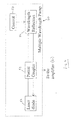
- FIG 4 is a schematic diagram showing an embodiment of the present invention in generic terms.
- a multiple wavelength pump (generally indicated by numeral 50) consists of a laser diode 52 coupled to a partial coupler 54 which is in turn coupled to means for providing adjustable optical feedback 56 under the control of control means 58.
- the means 56 is used to produce from the laser pump source 52 a plurality of wavelengths of pump radiation which may then be coupled to an amplifier 60 (not shown in Figure 4).
Landscapes
- Physics & Mathematics (AREA)
- Electromagnetism (AREA)
- Engineering & Computer Science (AREA)
- Computer Networks & Wireless Communication (AREA)
- Signal Processing (AREA)
- Optical Modulation, Optical Deflection, Nonlinear Optics, Optical Demodulation, Optical Logic Elements (AREA)
- Lasers (AREA)
- Optical Communication System (AREA)
Abstract
Description
Claims (12)
- A wide bandwidth Raman amplifier including a laser pump source of pump radiation, and means for producing from the pump source a plurality of wavelengths of pump radiation including means for independent power control of each radiation wavelength.
- An amplifier according to claim 1 including only one pump source.
- An amplifier according to claim 1 or claim 2 wherein the means for producing the plurality of pump radiation wavelengths includes one or more reflectors.
- An amplifier according to claim 3 wherein each reflector produces optical feedback to the pump source at one wavelength and the characteristics of the reflectors are selected such that each reflector produces optical feedback at a different wavelength to the wavelengths produced by the other reflectors.
- An amplifier according to any of the above claims wherein the means of power control of each pump radiation wavelength includes one or more variable optical attenuators.
- An amplifier according to claim 5 wherein there is a separate variable attenuator for each reflector.
- An amplifier according to any one of the above claims wherein at least some pump radiation of more than one wavelength is coupled to the signal to be amplified.
- An amplifier according to any of claims 5 to 6 including control means for controlling and/or adjusting the attenuation of each variable optical attenuator(s).
- An amplifier according to any one of claims 1-4 wherein the means for providing adjustable optical feedback includes one or more optical switches providing either substantially no attenuation or substantially 100% attenuation depending on the setting of the switch.
- An amplifier according to claim 9 including control means for selectively controlling the switches in order to change the overall characteristics of the amplifier.
- A method of providing a wide bandwidth Raman amplifier including the step of producing from a pump laser source, a plurality of wavelengths of pump radiation by providing adjustable optical feedback to the laser source at these wavelengths.
- A method of providing a wide bandwidth Raman amplifier including means for altering the amplifier gain profile during amplifier operation.
Applications Claiming Priority (2)
| Application Number | Priority Date | Filing Date | Title |
|---|---|---|---|
| GBGB0031508.5A GB0031508D0 (en) | 2000-12-22 | 2000-12-22 | Broadband raman amplifier |
| GB0031508 | 2000-12-22 |
Publications (3)
| Publication Number | Publication Date |
|---|---|
| EP1217764A2 true EP1217764A2 (en) | 2002-06-26 |
| EP1217764A3 EP1217764A3 (en) | 2004-03-31 |
| EP1217764B1 EP1217764B1 (en) | 2007-10-24 |
Family
ID=9905784
Family Applications (1)
| Application Number | Title | Priority Date | Filing Date |
|---|---|---|---|
| EP01310386A Expired - Lifetime EP1217764B1 (en) | 2000-12-22 | 2001-12-12 | Broadband raman amplifier |
Country Status (6)
| Country | Link |
|---|---|
| US (1) | US7154662B2 (en) |
| EP (1) | EP1217764B1 (en) |
| JP (1) | JP2002258336A (en) |
| AT (1) | ATE376724T1 (en) |
| DE (1) | DE60131063T2 (en) |
| GB (1) | GB0031508D0 (en) |
Families Citing this family (6)
| Publication number | Priority date | Publication date | Assignee | Title |
|---|---|---|---|---|
| DE10101742A1 (en) * | 2001-01-16 | 2002-07-25 | Siemens Ag | Pump source with several regulated pump lasers for optical broadband amplification of a WDM signal |
| JP3808734B2 (en) * | 2001-08-10 | 2006-08-16 | 富士通株式会社 | Raman amplifier |
| JP4175051B2 (en) * | 2002-08-02 | 2008-11-05 | 日本電気株式会社 | Optical transmission system and optical amplification method for optical transmission system |
| KR100487190B1 (en) * | 2003-04-22 | 2005-05-04 | 삼성전자주식회사 | Raman optical amplifier |
| KR100533914B1 (en) * | 2003-10-08 | 2005-12-06 | 한국전자통신연구원 | Raman amplifier and Raman pumping method |
| US7924497B2 (en) * | 2006-09-21 | 2011-04-12 | Tyco Electronics Subsea Communications Llc | System and method for gain equalization and optical communication system incorporating the same |
Family Cites Families (20)
| Publication number | Priority date | Publication date | Assignee | Title |
|---|---|---|---|---|
| US4699452A (en) * | 1985-10-28 | 1987-10-13 | American Telephone And Telegraph Company, At&T Bell Laboratories | Optical communications system comprising Raman amplification means |
| US4922495A (en) * | 1989-08-07 | 1990-05-01 | Rockwell International Corporation | Broad band crossed-beam raman amplifier |
| US5457568A (en) * | 1994-11-28 | 1995-10-10 | At&T Corp. | 980 NM pumped erbium fiber amplifier |
| KR0150486B1 (en) * | 1994-12-07 | 1998-12-01 | 양승택 | Wavelength-variable multi-wavelength fiber laser using single pump light source |
| DE19547603A1 (en) * | 1995-12-20 | 1997-06-26 | Sel Alcatel Ag | Optical amplifier device |
| AT403930B (en) | 1996-07-11 | 1998-06-25 | Voest Alpine Ind Anlagen | METHOD FOR CHARGING METAL CARRIERS IN A MELTING-GASIFICATION ZONE AND SYSTEM FOR IMPLEMENTING THE METHOD |
| US6122298A (en) * | 1996-11-01 | 2000-09-19 | Tyco Submarine Systems Ltd. | Multi-wavelength optical pump |
| US5920423A (en) * | 1997-12-05 | 1999-07-06 | Sdl, Inc. | Multiple pumped fiber amplifiers for WDM communication systems with adjustment for the amplifier signal gain bandwidth |
| EP1055299A2 (en) * | 1998-02-20 | 2000-11-29 | SDL, Inc. | Upgradable, gain flattened fiber amplifiers for wdm applications |
| US6344922B1 (en) * | 1998-07-21 | 2002-02-05 | Corvis Corporation | Optical signal varying devices |
| EP2306605B1 (en) * | 1998-07-23 | 2012-05-23 | The Furukawa Electric Co., Ltd. | Pumping unit for a Raman amplifier and Raman amplifier comprising the same |
| US6163552A (en) * | 1998-08-14 | 2000-12-19 | Lucent Technologies Inc. | Article comprising an optical fiber cascaded Raman resonator |
| US6407855B1 (en) * | 1999-10-29 | 2002-06-18 | Sdl, Inc. | Multiple wavelength optical sources |
| KR100319748B1 (en) * | 1999-12-09 | 2002-01-09 | 오길록 | Wideband multichannel fiber lasers with output power equalization |
| US6433920B1 (en) * | 2000-04-27 | 2002-08-13 | Jds Uniphase Corporation | Raman-based utility optical amplifier |
| US6717963B1 (en) * | 2000-07-14 | 2004-04-06 | Tyco Telecommunications (Us) Inc. | Raman fiber amplifier using a wide bandwidth continuous wave pump |
| US6657774B1 (en) * | 2000-08-18 | 2003-12-02 | Corning Incorporated | Amplifier system with distributed and discrete Raman fiber amplifiers |
| JP4821037B2 (en) * | 2000-08-25 | 2011-11-24 | 富士通株式会社 | Optical amplifier and Raman pump light source using Raman amplification |
| JP2002076482A (en) * | 2000-08-31 | 2002-03-15 | Fujitsu Ltd | Optical amplifier, optical amplification method, and optical amplification system |
| JP4626918B2 (en) * | 2001-03-02 | 2011-02-09 | 富士通株式会社 | Raman optical repeater |
-
2000
- 2000-12-22 GB GBGB0031508.5A patent/GB0031508D0/en not_active Ceased
-
2001
- 2001-12-12 EP EP01310386A patent/EP1217764B1/en not_active Expired - Lifetime
- 2001-12-12 AT AT01310386T patent/ATE376724T1/en not_active IP Right Cessation
- 2001-12-12 DE DE60131063T patent/DE60131063T2/en not_active Expired - Lifetime
- 2001-12-20 JP JP2001387119A patent/JP2002258336A/en not_active Withdrawn
- 2001-12-20 US US10/022,896 patent/US7154662B2/en not_active Expired - Fee Related
Also Published As
| Publication number | Publication date |
|---|---|
| GB0031508D0 (en) | 2001-02-07 |
| DE60131063T2 (en) | 2008-08-07 |
| EP1217764B1 (en) | 2007-10-24 |
| ATE376724T1 (en) | 2007-11-15 |
| EP1217764A3 (en) | 2004-03-31 |
| US20020085268A1 (en) | 2002-07-04 |
| JP2002258336A (en) | 2002-09-11 |
| US7154662B2 (en) | 2006-12-26 |
| DE60131063D1 (en) | 2007-12-06 |
Similar Documents
| Publication | Publication Date | Title |
|---|---|---|
| JP4626918B2 (en) | Raman optical repeater | |
| US6862133B2 (en) | Raman amplifier and wavelength division multiplexing optical communication system, and method of controlling raman amplification | |
| JP2734969B2 (en) | Optical fiber amplifier for WDM transmission | |
| KR960006371A (en) | Amplified telecommunications system for wavelength division multiplexed transmission with equalized receive power | |
| WO1997050157A1 (en) | Optical amplifier modules | |
| KR20020008772A (en) | Raman amplifier | |
| US6421167B1 (en) | Multiple function bandwidth management systems | |
| JPH11509070A (en) | Variable gain type optical amplifier having a constant pass band and optical link loss change automatic compensation system including the amplifier | |
| EP1217764B1 (en) | Broadband raman amplifier | |
| KR100283866B1 (en) | Gain Control Device and Method of Fiber Optic Amplifier | |
| US6256140B1 (en) | Optical amplifying apparatus for transmitting wavelength division multiplexed signal light and optical network apparatus with using the same | |
| US7627207B2 (en) | Dispersion compensating method and dispersion compensating apparatus | |
| US6836488B2 (en) | Cascaded Raman fiber laser, and optical system including such a laser | |
| US20040160994A1 (en) | Multiple wavelength laser system | |
| EP1788730B1 (en) | Optical amplification unit with span loss tilt compensation | |
| US7158288B2 (en) | Long-wavelength-band gain-controlled optical amplifier | |
| EP1562313A2 (en) | Raman optical amplifier, optical transmission system using the same, and Raman optical amplification method | |
| US20030095738A1 (en) | Planar optical circuit and optical transmission system | |
| JP3740849B2 (en) | Optical amplifier | |
| US20030184848A1 (en) | Raman fiber amplification stage, optical system and method to control the Raman amplification | |
| US6937389B1 (en) | Optical communication systems and optical amplifiers employing periodic combiners and methods | |
| KR20040067082A (en) | Multi wavelength light source using fiber grating | |
| HK1031053B (en) | Optical amplifier with gain adjustment | |
| CA2341825A1 (en) | Multiple wavelength laser source | |
| HK1031053A1 (en) | Optical amplifier with gain adjustment |
Legal Events
| Date | Code | Title | Description |
|---|---|---|---|
| PUAI | Public reference made under article 153(3) epc to a published international application that has entered the european phase |
Free format text: ORIGINAL CODE: 0009012 |
|
| AK | Designated contracting states |
Kind code of ref document: A2 Designated state(s): AT BE CH CY DE DK ES FI FR GB GR IE IT LI LU MC NL PT SE TR |
|
| AX | Request for extension of the european patent |
Free format text: AL;LT;LV;MK;RO;SI |
|
| PUAL | Search report despatched |
Free format text: ORIGINAL CODE: 0009013 |
|
| AK | Designated contracting states |
Kind code of ref document: A3 Designated state(s): AT BE CH CY DE DK ES FI FR GB GR IE IT LI LU MC NL PT SE TR |
|
| AX | Request for extension of the european patent |
Extension state: AL LT LV MK RO SI |
|
| 17P | Request for examination filed |
Effective date: 20040930 |
|
| 17Q | First examination report despatched |
Effective date: 20041108 |
|
| AKX | Designation fees paid |
Designated state(s): AT BE CH CY DE DK ES FI FR GB GR IE IT LI LU MC NL PT SE TR |
|
| GRAP | Despatch of communication of intention to grant a patent |
Free format text: ORIGINAL CODE: EPIDOSNIGR1 |
|
| RAP1 | Party data changed (applicant data changed or rights of an application transferred) |
Owner name: ALCATEL LUCENT |
|
| RIN1 | Information on inventor provided before grant (corrected) |
Inventor name: ZARRIS, GEORGE Inventor name: RODRIGUEZ LLORENTE, FERNANDO |
|
| GRAS | Grant fee paid |
Free format text: ORIGINAL CODE: EPIDOSNIGR3 |
|
| GRAA | (expected) grant |
Free format text: ORIGINAL CODE: 0009210 |
|
| AK | Designated contracting states |
Kind code of ref document: B1 Designated state(s): AT BE CH CY DE DK ES FI FR GB GR IE IT LI LU MC NL PT SE TR |
|
| REG | Reference to a national code |
Ref country code: GB Ref legal event code: FG4D |
|
| REG | Reference to a national code |
Ref country code: CH Ref legal event code: EP |
|
| REG | Reference to a national code |
Ref country code: IE Ref legal event code: FG4D |
|
| REF | Corresponds to: |
Ref document number: 60131063 Country of ref document: DE Date of ref document: 20071206 Kind code of ref document: P |
|
| NLV1 | Nl: lapsed or annulled due to failure to fulfill the requirements of art. 29p and 29m of the patents act | ||
| PG25 | Lapsed in a contracting state [announced via postgrant information from national office to epo] |
Ref country code: SE Free format text: LAPSE BECAUSE OF FAILURE TO SUBMIT A TRANSLATION OF THE DESCRIPTION OR TO PAY THE FEE WITHIN THE PRESCRIBED TIME-LIMIT Effective date: 20080124 Ref country code: CH Free format text: LAPSE BECAUSE OF FAILURE TO SUBMIT A TRANSLATION OF THE DESCRIPTION OR TO PAY THE FEE WITHIN THE PRESCRIBED TIME-LIMIT Effective date: 20071024 Ref country code: LI Free format text: LAPSE BECAUSE OF FAILURE TO SUBMIT A TRANSLATION OF THE DESCRIPTION OR TO PAY THE FEE WITHIN THE PRESCRIBED TIME-LIMIT Effective date: 20071024 Ref country code: ES Free format text: LAPSE BECAUSE OF FAILURE TO SUBMIT A TRANSLATION OF THE DESCRIPTION OR TO PAY THE FEE WITHIN THE PRESCRIBED TIME-LIMIT Effective date: 20080204 Ref country code: NL Free format text: LAPSE BECAUSE OF FAILURE TO SUBMIT A TRANSLATION OF THE DESCRIPTION OR TO PAY THE FEE WITHIN THE PRESCRIBED TIME-LIMIT Effective date: 20071024 |
|
| REG | Reference to a national code |
Ref country code: CH Ref legal event code: PL |
|
| PG25 | Lapsed in a contracting state [announced via postgrant information from national office to epo] |
Ref country code: PT Free format text: LAPSE BECAUSE OF FAILURE TO SUBMIT A TRANSLATION OF THE DESCRIPTION OR TO PAY THE FEE WITHIN THE PRESCRIBED TIME-LIMIT Effective date: 20080324 |
|
| PG25 | Lapsed in a contracting state [announced via postgrant information from national office to epo] |
Ref country code: AT Free format text: LAPSE BECAUSE OF FAILURE TO SUBMIT A TRANSLATION OF THE DESCRIPTION OR TO PAY THE FEE WITHIN THE PRESCRIBED TIME-LIMIT Effective date: 20071024 |
|
| ET | Fr: translation filed | ||
| PG25 | Lapsed in a contracting state [announced via postgrant information from national office to epo] |
Ref country code: MC Free format text: LAPSE BECAUSE OF NON-PAYMENT OF DUE FEES Effective date: 20071231 Ref country code: DK Free format text: LAPSE BECAUSE OF FAILURE TO SUBMIT A TRANSLATION OF THE DESCRIPTION OR TO PAY THE FEE WITHIN THE PRESCRIBED TIME-LIMIT Effective date: 20071024 |
|
| PG25 | Lapsed in a contracting state [announced via postgrant information from national office to epo] |
Ref country code: BE Free format text: LAPSE BECAUSE OF FAILURE TO SUBMIT A TRANSLATION OF THE DESCRIPTION OR TO PAY THE FEE WITHIN THE PRESCRIBED TIME-LIMIT Effective date: 20071024 |
|
| PLBE | No opposition filed within time limit |
Free format text: ORIGINAL CODE: 0009261 |
|
| STAA | Information on the status of an ep patent application or granted ep patent |
Free format text: STATUS: NO OPPOSITION FILED WITHIN TIME LIMIT |
|
| 26N | No opposition filed |
Effective date: 20080725 |
|
| PG25 | Lapsed in a contracting state [announced via postgrant information from national office to epo] |
Ref country code: IE Free format text: LAPSE BECAUSE OF NON-PAYMENT OF DUE FEES Effective date: 20071212 |
|
| PG25 | Lapsed in a contracting state [announced via postgrant information from national office to epo] |
Ref country code: GR Free format text: LAPSE BECAUSE OF FAILURE TO SUBMIT A TRANSLATION OF THE DESCRIPTION OR TO PAY THE FEE WITHIN THE PRESCRIBED TIME-LIMIT Effective date: 20080125 |
|
| PG25 | Lapsed in a contracting state [announced via postgrant information from national office to epo] |
Ref country code: FI Free format text: LAPSE BECAUSE OF FAILURE TO SUBMIT A TRANSLATION OF THE DESCRIPTION OR TO PAY THE FEE WITHIN THE PRESCRIBED TIME-LIMIT Effective date: 20071024 |
|
| PG25 | Lapsed in a contracting state [announced via postgrant information from national office to epo] |
Ref country code: CY Free format text: LAPSE BECAUSE OF FAILURE TO SUBMIT A TRANSLATION OF THE DESCRIPTION OR TO PAY THE FEE WITHIN THE PRESCRIBED TIME-LIMIT Effective date: 20071024 |
|
| PG25 | Lapsed in a contracting state [announced via postgrant information from national office to epo] |
Ref country code: LU Free format text: LAPSE BECAUSE OF NON-PAYMENT OF DUE FEES Effective date: 20071212 |
|
| PG25 | Lapsed in a contracting state [announced via postgrant information from national office to epo] |
Ref country code: TR Free format text: LAPSE BECAUSE OF FAILURE TO SUBMIT A TRANSLATION OF THE DESCRIPTION OR TO PAY THE FEE WITHIN THE PRESCRIBED TIME-LIMIT Effective date: 20071024 |
|
| PG25 | Lapsed in a contracting state [announced via postgrant information from national office to epo] |
Ref country code: IT Free format text: LAPSE BECAUSE OF NON-PAYMENT OF DUE FEES Effective date: 20071231 |
|
| REG | Reference to a national code |
Ref country code: GB Ref legal event code: 732E Free format text: REGISTERED BETWEEN 20130926 AND 20131002 |
|
| REG | Reference to a national code |
Ref country code: FR Ref legal event code: GC Effective date: 20131018 |
|
| REG | Reference to a national code |
Ref country code: FR Ref legal event code: RG Effective date: 20141016 |
|
| REG | Reference to a national code |
Ref country code: FR Ref legal event code: CA Effective date: 20150521 |
|
| REG | Reference to a national code |
Ref country code: FR Ref legal event code: CA Effective date: 20150521 |
|
| REG | Reference to a national code |
Ref country code: FR Ref legal event code: PLFP Year of fee payment: 15 |
|
| REG | Reference to a national code |
Ref country code: FR Ref legal event code: PLFP Year of fee payment: 16 |
|
| PGFP | Annual fee paid to national office [announced via postgrant information from national office to epo] |
Ref country code: FR Payment date: 20161222 Year of fee payment: 16 |
|
| PGFP | Annual fee paid to national office [announced via postgrant information from national office to epo] |
Ref country code: DE Payment date: 20171211 Year of fee payment: 17 |
|
| PGFP | Annual fee paid to national office [announced via postgrant information from national office to epo] |
Ref country code: GB Payment date: 20171221 Year of fee payment: 17 |
|
| REG | Reference to a national code |
Ref country code: FR Ref legal event code: ST Effective date: 20180831 |
|
| PG25 | Lapsed in a contracting state [announced via postgrant information from national office to epo] |
Ref country code: FR Free format text: LAPSE BECAUSE OF NON-PAYMENT OF DUE FEES Effective date: 20180102 |
|
| REG | Reference to a national code |
Ref country code: GB Ref legal event code: 732E Free format text: REGISTERED BETWEEN 20190429 AND 20190502 |
|
| REG | Reference to a national code |
Ref country code: DE Ref legal event code: R082 Ref document number: 60131063 Country of ref document: DE Representative=s name: MENZIETTI WETZEL, DE Ref country code: DE Ref legal event code: R081 Ref document number: 60131063 Country of ref document: DE Owner name: PROVENANCE ASSET GROUP LLC, PITTSFORD, US Free format text: FORMER OWNER: ALCATEL LUCENT, PARIS, FR |
|
| REG | Reference to a national code |
Ref country code: DE Ref legal event code: R119 Ref document number: 60131063 Country of ref document: DE |
|
| GBPC | Gb: european patent ceased through non-payment of renewal fee |
Effective date: 20181212 |
|
| PG25 | Lapsed in a contracting state [announced via postgrant information from national office to epo] |
Ref country code: DE Free format text: LAPSE BECAUSE OF NON-PAYMENT OF DUE FEES Effective date: 20190702 |
|
| PG25 | Lapsed in a contracting state [announced via postgrant information from national office to epo] |
Ref country code: GB Free format text: LAPSE BECAUSE OF NON-PAYMENT OF DUE FEES Effective date: 20181212 |