EP1217675A2 - Separator for fuel cell and manufacture method for the same - Google Patents
Separator for fuel cell and manufacture method for the same Download PDFInfo
- Publication number
- EP1217675A2 EP1217675A2 EP01124834A EP01124834A EP1217675A2 EP 1217675 A2 EP1217675 A2 EP 1217675A2 EP 01124834 A EP01124834 A EP 01124834A EP 01124834 A EP01124834 A EP 01124834A EP 1217675 A2 EP1217675 A2 EP 1217675A2
- Authority
- EP
- European Patent Office
- Prior art keywords
- resin
- separator
- molding
- graphite
- graphite powder
- Prior art date
- Legal status (The legal status is an assumption and is not a legal conclusion. Google has not performed a legal analysis and makes no representation as to the accuracy of the status listed.)
- Granted
Links
Images


Classifications
-
- H—ELECTRICITY
- H01—ELECTRIC ELEMENTS
- H01M—PROCESSES OR MEANS, e.g. BATTERIES, FOR THE DIRECT CONVERSION OF CHEMICAL ENERGY INTO ELECTRICAL ENERGY
- H01M8/00—Fuel cells; Manufacture thereof
- H01M8/02—Details
- H01M8/0202—Collectors; Separators, e.g. bipolar separators; Interconnectors
- H01M8/0204—Non-porous and characterised by the material
- H01M8/0223—Composites
- H01M8/0226—Composites in the form of mixtures
-
- H—ELECTRICITY
- H01—ELECTRIC ELEMENTS
- H01M—PROCESSES OR MEANS, e.g. BATTERIES, FOR THE DIRECT CONVERSION OF CHEMICAL ENERGY INTO ELECTRICAL ENERGY
- H01M8/00—Fuel cells; Manufacture thereof
- H01M8/02—Details
- H01M8/0202—Collectors; Separators, e.g. bipolar separators; Interconnectors
- H01M8/0204—Non-porous and characterised by the material
- H01M8/0223—Composites
- H01M8/0228—Composites in the form of layered or coated products
-
- H—ELECTRICITY
- H01—ELECTRIC ELEMENTS
- H01M—PROCESSES OR MEANS, e.g. BATTERIES, FOR THE DIRECT CONVERSION OF CHEMICAL ENERGY INTO ELECTRICAL ENERGY
- H01M8/00—Fuel cells; Manufacture thereof
- H01M8/02—Details
- H01M8/0202—Collectors; Separators, e.g. bipolar separators; Interconnectors
- H01M8/0204—Non-porous and characterised by the material
- H01M8/0213—Gas-impermeable carbon-containing materials
-
- H—ELECTRICITY
- H01—ELECTRIC ELEMENTS
- H01M—PROCESSES OR MEANS, e.g. BATTERIES, FOR THE DIRECT CONVERSION OF CHEMICAL ENERGY INTO ELECTRICAL ENERGY
- H01M8/00—Fuel cells; Manufacture thereof
- H01M8/02—Details
- H01M8/0202—Collectors; Separators, e.g. bipolar separators; Interconnectors
- H01M8/0204—Non-porous and characterised by the material
- H01M8/0221—Organic resins; Organic polymers
-
- Y—GENERAL TAGGING OF NEW TECHNOLOGICAL DEVELOPMENTS; GENERAL TAGGING OF CROSS-SECTIONAL TECHNOLOGIES SPANNING OVER SEVERAL SECTIONS OF THE IPC; TECHNICAL SUBJECTS COVERED BY FORMER USPC CROSS-REFERENCE ART COLLECTIONS [XRACs] AND DIGESTS
- Y02—TECHNOLOGIES OR APPLICATIONS FOR MITIGATION OR ADAPTATION AGAINST CLIMATE CHANGE
- Y02E—REDUCTION OF GREENHOUSE GAS [GHG] EMISSIONS, RELATED TO ENERGY GENERATION, TRANSMISSION OR DISTRIBUTION
- Y02E60/00—Enabling technologies; Technologies with a potential or indirect contribution to GHG emissions mitigation
- Y02E60/30—Hydrogen technology
- Y02E60/50—Fuel cells
-
- Y—GENERAL TAGGING OF NEW TECHNOLOGICAL DEVELOPMENTS; GENERAL TAGGING OF CROSS-SECTIONAL TECHNOLOGIES SPANNING OVER SEVERAL SECTIONS OF THE IPC; TECHNICAL SUBJECTS COVERED BY FORMER USPC CROSS-REFERENCE ART COLLECTIONS [XRACs] AND DIGESTS
- Y02—TECHNOLOGIES OR APPLICATIONS FOR MITIGATION OR ADAPTATION AGAINST CLIMATE CHANGE
- Y02P—CLIMATE CHANGE MITIGATION TECHNOLOGIES IN THE PRODUCTION OR PROCESSING OF GOODS
- Y02P70/00—Climate change mitigation technologies in the production process for final industrial or consumer products
- Y02P70/50—Manufacturing or production processes characterised by the final manufactured product
Definitions
- the present invention relates to a separator for a fuel cell and to a manufacture method of the separator.
- a fuel cell for example, a solid polymer type is produced by composing unit cells each assembled by installing an anode and a cathode while sandwiching a solid polymer film between them and separators, and by stacking the unit cells in number of several hundreds.
- a fuel gas such as hydrogen or the like is supplied through a gas supply groove formed in one separator in anode side and an oxidizing gas such as oxygen or the like is supplied to the cathode side to cause electrochemical reaction to convert the chemical energy which the fuel has into the electric energy as output.
- the separators are required to have contact resistance as low as possible between surfaces of the neighboring separators and between the contact surfaces of the separators and the electrodes closely attached to the separators and are required to have the intrinsic resistance of the separators themselves (hereinafter referred also as to volume resistance) as low as possible as well.
- the separators are required to have sufficiently high mechanical strength and excellent molding precision as well from a viewpoint that fuel cells are assembled by stacking several hundreds of separators and fastening and fixing them.
- separators required to have such characteristic properties well-known ones are isomg, for example, metal sheets of such as pure copper, a stainless steel and the like, however, in the case of such a metallic material, there is a problem that material deterioration is easy to be caused by hydrogen embrittlement owing to contact with hydrogen gas as a fuel gas and such a metal material is insufficient for a long time stability.
- those which have recently been developed are fuel cells employing a molded body produced by mixing a graphite powder with a thermosetting resin such as phenol resin as a binder and pressure molding the resulting mixture as separators. Since the graphite has a low electric resistance and excellent corrosion resistance, the above described problem in the case of using a metal can be improved. Further, since the void gaps formed in the inside of the compacted powder molded body are filled with the binder, gas impermeability to a certain extent can be obtained.
- Such a separator made of graphite has conventionally been produced by, for example, using a resin-mixed graphite powder produced by steps of stirring thermosetting resin such as powder phenol resin with a volatile organic solvent such as an alcohol to obtain slurry, mixing and kneading a graphite powder with the slurry, drying the resulting mixture, and then pulverizing the dried mixture to a prescribed average particle diameter.
- thermosetting resin such as powder phenol resin
- a volatile organic solvent such as an alcohol
- a separator made of graphite has been produced by specifying at first the resin amount sufficient to satisfy the factors such as the mechanical strength and the gas impermeability necessary for a separator of a fuel cell.
- a conventional separator made of graphite produced by the above described production method does not necessarily satisfy the electric characteristic properties such as volume resistance and the like.
- the electric characteristic properties become more excellent as the resin amount is less, the resin amount cannot be decreased so much since the mechanical strength and the gas impermeability are decreased if the resin amount is decreased and for that, a conventional separator is not provided with excellent electric characteristic properties as well.
- the present invention is developed taking the above described problem into consideration and the purpose is to provide a separator for a fuel cell made of a graphite and having mechanical strength and gas impermeability as well as electric characteristic properties and to provide a method for producing the separator.
- the separator for a fuel cell of the present invention is made of a molded body produced by filling a molding die with a graphite powder coated with resin on the surface and molding the powder by applying pressure into a prescribed separate shape.
- a conventional separator made of graphite is produced by kneading resin and a graphite powder and then obtaining a raw material powder containing graphite whose surface is exposed by a pulverization step before the pressure-molding while taking the conductivity after the molding into consideration and pressure-molding the raw material powder. Consequently, resin partially attaches to the surface of the graphite and with a raw material powder in such a state, even if pressure-molding is carried out by a molding die filled with such a raw material powder, the isostatic fluidity of respective particles through resin cannot be obtained.
- a graphite powder cannot sufficiently be coated with resin and for that, relatively large void gaps are easily left among the particles in a produced molded body. As a result, if the content of the resin is decreased, the strength and the gas impermeability are decreased.
- the separator of this invention is produced by filling a molding die with a graphite powder whose surface is previously sufficiently coated with resin and by pressure-molding the powder, and in this case, the fluidity of the respective graphite particles is improved in the molding die to produce a molded body with a small porosity. Further, the neighboring graphite particles are closely stuck to one another while the resin being eliminated toward the voids among the graphite particles at the time of the pressure-molding and consequently, the conductivity among graphite particles is provided also at the pressure-molding.
- pressure molding of, for example, a graphite powder coated with resin on the surface and having the particle diameter of 15 to 125 ⁇ m at the molding pressure of 100 to 1,000 kg/cm 2 and the molding temperature of 120 to 240°C gives a molded body having 40 MPa of bending strength or higher and excellent in mechanical strength and 10 ⁇ 10 -8 cc ⁇ cm/cm 2 ⁇ sec ⁇ atm of gas permeability or lower and 10 ⁇ 10 -3 ⁇ cm of the volume resistance or lower and excellent in electric characteristic properties even if the resin content is as low as 10 to 24 wt.% and the obtained molded body can suitably be used as a separator for a fuel cell.
- the fuel cell-based battery is assembled in a stack structure by stacking unit cells 5 in number of several hundreds, each composed of a solid polymer film 1, which is an ion exchange membrane made of fluoro resin, for example, an anode 2 and a cathode 3 sandwiching the solid polymer film 1 from both sides, and separators 4 ⁇ 4 further sandwiching them from both sides, and disposing current collector plates, which are omitted in the figure, in both sides of the united cells.
- Each anode 2 and each cathode 3 are made of carbon cloth woven from carbon fiber yarn, carbon paper, or carbon felt.
- each separator 4 has fuel gas holes 6 ⁇ 7 and oxidizing gas holes 8 ⁇ 9 in the peripheral part to pass a hydrogen-containing fuel gas though and to pass an oxygen-containing oxidizing gas through, respectively.
- the respective holes 6 to 9 penetrate the inside of each fuel cell in the longitudinal direction to form a fuel gas supply manifold, a fuel gas discharge manifold, an oxidizing gas supply manifold, and an oxidizing gas discharge manifold.
- a flow channel of a groove part 12 with an optional pattern is formed.
- the pattern of the groove part 12 may be formed to be, for example, a lattice like shape among a large number of projected parts other than the shape illustrated in the figure.
- a fuel gas flow channel 13 is formed between the surface of an anode 2 and a separator 4 in the separator 4 in the anode 2 side and a cooling water flow channel 14 is formed between the separator 4 and another neighboring separator 4.
- an oxidizing gas flow channel 15 is formed between the separator 4 and the surface of the cathode 3.
- a hydrogen-containing fuel gas is supplied from a fuel gas supply apparatus installed in the outside to the fuel gas flow channel 13 of each unit cell 5 through the above-described fuel gas supply manifold and in the anode 2 side of each unit cell 5, the electrochemical reaction; H 2 ⁇ 2H + + 2e - ; is caused.
- the fuel gas after the reaction is discharged outside through the flue gas flow channel 13 of each unit cell 5 and the fuel gas discharge manifold.
- an oxygen-containing oxidizing gas (air) is supplied from an oxidizing gas supply apparatus installed in the outside to the oxidizing gas flow channel 15 of each unit cell 5 through the above described oxidizing gas supply manifold and in the anode 3 side of each unit cell 5, the electrochemical reaction; O 2 + 4H + + 4e - ⁇ 2H 2 O; is caused.
- the oxidizing gas after the reaction is discharged outside through the oxidizing gas flow channel 15 of each unit cell 5 and the oxidizing gas discharge manifold.
- the fuel cell-based battery is operated in a temperature range of about 80 to 100°C and during the operation, cooling water is supplied from a cooling water supply apparatus installed in the outside and circulated through the above described cooling water channel 14 to keep the operation temperature within the above described temperature range.
- the said each separator 4 is formed generally to be a thin sheet-like shape with the thickness of about 1 to 3 mm and a groove part 12 with the depth of 0.3 to 1.5 mm is formed in both side in the case of a separator 4 in the anode 2 side and in one side in the case of a separator 4 in the cathode 3 side so as to form the said fuel gas flow channel 13, the cooling water flow channel 14, and the oxidizing gas flow channel 15.
- a separator of the present invention to be employed for a solid polymer type fuel cell-based battery just as described above is made of a molded body produced by pressure-molding a graphite powder coated with resin on the surface into a prescribed separate shape under the molding conditions which will be described later.
- the molded body has excellent mechanical strength as 40 MPa of bending strength or higher, characteristic property as a material of 10 ⁇ 10 -8 cc ⁇ cm/cm 2 ⁇ sec ⁇ atm of gas permeability or lower, and electric characteristic property of 10 ⁇ 10 -3 ⁇ cm of the volume resistance or lower although the content of resin in the molded body is about 10 to 24 wt.%, less than that of a conventional one.
- the production method of such a separator made of graphite will be described.
- the graphite powder to be used may be any kind of graphite such as natural graphite, artificial graphite, carbon black, kish graphite, and expanded graphite, and the like and may optionally be selected while taking the conditions of such as the cost into consideration.
- Natural graphite and artificial graphite are preferable in terms of the electric properties.
- the average particle diameter of the graphite powder to be used is preferable in a range of 15 to 125 ⁇ m. If it is smaller than 15 ⁇ m, the electric resistance cannot sufficiently be decreased and if it is larger than 125 ⁇ m, the strength is deteriorated.
- the resin most preferable is phenol resin excellent in wettability with the graphite powder and also preferable are any kind of resol type resin and novolak type resin.
- the method for producing such a graphite powder coated with resin is not particularly restricted and, for example, a resin solution diluted with an organic solvent with a low viscosity such as methanol, for example, a phenol resin solution, is mixed with a graphite powder and stirred and kneaded to be a slurry and then the slurry is granulated and dried by a spray drier to produce such a graphite powder.
- the mixing ratio at the above described mixing and kneading time is adjusted so as to control the resin content after the formation of the molded body to be 10 to 24 wt.%, preferably 14 to 18 wt.%. If the resin content is less than 10 wt.%, the excellent gas impermeability is difficult to be obtained and if the content is more than 24 wt.%, the volume resistance and the contact resistance, which will be described later, are increased.
- the resin-coated graphite powder can be produced by a method in which polymerization reaction of resin takes place on the surface of the graphite powder during the stirring of the resin raw material solution.
- a graphite powder is further added to a reaction container loaded with phenols, formaldehydes, a reaction catalyst, and another general reaction solvent and the mixture is heated to a prescribed temperature while being mixed and stirred to produce a resin-coated graphite powder in which the phenol resin adheres to the surface of the graphite powder and enters in lamellar graphite powder to firmly stick to the graphite powder.
- the said phenols denote phenol and phenol derivatives and other than phenol, examples are trifunctional ones such as m-cresol, resorcinol, and 3,5-xylenol; tetrafunctional ones such as bisphenol A, and dihydroxydiphenylmethane; bifunctional o- or p-substituted phenol such as o-cresol, p-cresol, p-tert-butylphenol, p-phenylphenol, p-cumylphenol, p-nonylphenol, 2,4- or 2,6-xylenol, and the like.
- halophenols having chlorine or bromine as a substitutent are also usable and other than using solely one selected from those, a plurality of those compounds may be used as a mixture.
- formalin is most suitable and those in form of paraformaldehyde may be used and besides, some or most of formaldehyde may be substituted with furfural or furfuryl alcohol to be used.
- reaction catalyst preferable are those capable of producing -NCH 2 , or -OCH 2 or -SCH 2 bond between the benzene ring of the phenols and a benzene ring as a final structural formula of the phenol resin.
- usable are hexamethylene tetramine, ammonia, and basic substances such as primary and secondary amines, e.g. methylamine, dimethylamine, ethylenediamine, monoethanolamine and the like.
- a basic catalyst such as hydroxides of alkali metals and alkaline earth metals and tertiary amines, which are commonly used at the time of phenol resin synthesis.
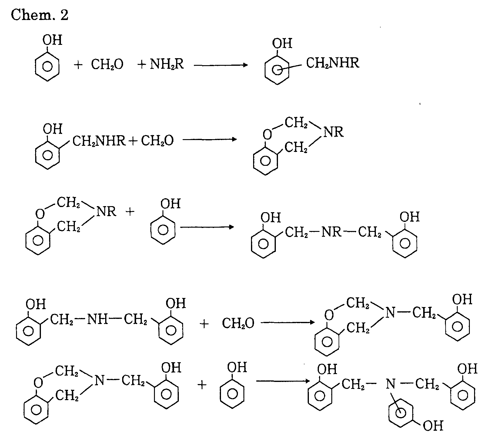
- the phenol resin obtained is phenol resin having -SCH 2 bond between benzene rings other than the phenol resin shown as Chem. 1 and Chem. 2.
- the resin-coated graphite powder obtained by the above described production method is filled in a die having a molding space corresponding to a prescribed separator shape and pressure-molded in molding conditions; molding pressure of 100 to 1,000 kg/cm 2 and molding temperature of 120 to 240°C. If the molding pressure is lower than 100 kg/cm 2 , the density of the obtained molded body is low and the volume resistance becomes high to make a separator excellent in conductivity hard to be obtained. On the other hand, if excess plane pressure higher than 1,000 kg/cm 2 is applied, the phenomenon that resin is extruded out the graphite particles and unevenly distributed in the peripheral regions of the molded body dominantly takes place and for that the contact resistance, which will be described later, is increased.
- the molding temperature can properly be set corresponding to the heating properties of the resin, it is preferable to set the temperature generally at 120°C or higher as described above in order to obtain the good fluidity of the graphite powder and the good molding property in the molding die in the case the resin content is small. If the temperature exceeds 240°C, the swelling phenomenon of the molded body occurs and if the temperature is further increased, resin carbonization takes place.
- the separator of the present invention can be produced using a graphite powder 21 whose surface coated with resin 20 by filling a molding die with the graphite powder and molding the graphite powder in the above described molding conditions.
- the respective graphite particles show fluidity responding to the resin in the molding die and due to that, the obtained molded body is well fitted with the die even after the resin is hardened, that is, the obtained molded body is provided with a high shape precision.
- the resin 20 covering the surface of the respective raw material graphite particles 21 flows toward the voids B among the respective raw material graphite particles 21 along the surface of the respective raw material graphite particles 21 in the regions A among the respective raw material graphite particles 21 contacting one another during the molding pressure application.
- the surfaces of neighboring raw material graphite particles 21 are brought into contact with one another and good electric communication state is produced among these raw material graphite particles 21.
- the resin extruded out the regions where particles are brought into contact with one another as describe above gathers in gaps surrounded with the respective raw material graphite particles 21 to fill the gaps.
- fluidity of the resin 20 is evenly generated around the respective raw material graphite particles 21 entirely in the inside of the molding die, so that the respective raw material graphite particles 21 surrounding the gaps are also firmly bonded to one another through the resin filling the gaps to form a molded body.
- the inner resistance is considerably affected by the contact resistance between mutually closely attached separators in neighboring unit cells 5 ⁇ 5 in addition to the volume resistance of the separator itself.
- such a contact resistance is also extremely low.
- the resin content cannot be decreased to, for example, around 30 wt.% or lower because of the above described reasons and at the time when a graphite powder mixed with such a high amount of the resin is pressure-molded, the resin is extruded out to the peripheral part of the molded body from the gaps among the graphite particles to increase the resin ratio in the surface of the molded body.
- the separator has a high contact resistance as described above.
- the separator of the present invention even if the resin content is decreased to 24 wt.% or lower, the desired mechanical strength and gas impermeability can be maintained, and the separator obtained is provided with a low contact resistance as described above. Consequently, using such a separator, a fuel cell-based battery with low inner resistance and high power generation efficiency can be assembled. Further, the thickness of the separator can be made thin and consequently, the fuel cell-based battery can be made small and light in weight.
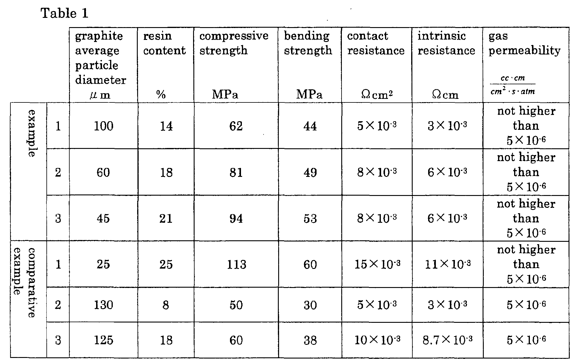
- a reaction container was loaded with a graphite powder with the average particle size of 100 ⁇ m, phenol, formaldehyde, reaction catalyst (hexamethylenetetramine or ammonia together with a caustic soda solution), and a reaction solvent and while being mixed and stirred, the mixture was heated at 80°C for 1 hour.
- the content of the reaction container was cooled to a room temperature and after the stirring was stopped, the black granular substance precipitated separately from the solvent in the reaction container was discharged out and washed with water.
- the resulting substance was filtered to be separated from the solvent and dried to obtain a resin-coated graphite powder.
- the content of the resin in the resin-coated graphite was 14%.
- the resin-coated graphite powder was filled in a molding die and pressure-molded at molding pressure of 200 kg/cm 2 and molding temperature of 160°C to produce a specimen for measuring a variety of characteristic properties, which will be described later.
- a resin-coated graphite powder was produced in the same manner as the example 1, except that the raw material graphite powder with the average particle diameter of 60 ⁇ m was used in place of the graphite powder in the example 1.
- the content of the resin in the resin-coated graphite was 18%.
- a specimen was produced in the same molding manner as described above in the same molding conditions as those of the example 1.
- a resin-coated graphite powder was produced in the same manner as the example 1, except that the raw material graphite powder with the average particle diameter of 45 ⁇ m was used in place of the graphite powder in the example 1.
- the content of the resin in the resin-coated graphite was 21%.
- a specimen was produced in the same molding manner as described above in the same molding conditions as those of the example 1.
- a resin-coated graphite powder was produced in the same manner as the example 1, except that the raw material graphite powder with the average particle diameter of 25 ⁇ m was used in place of the graphite powder in the example 1. The content of the resin in the resin-coated graphite was 25%. Next, using the obtained resin-coated graphite powder, a specimen was produced in the same molding manner as described above in the same molding conditions as those of the example 1.
- a resin-coated graphite powder was produced in the same manner as the example 1, except that the raw material graphite powder with the average particle diameter of 130 ⁇ m was used in place of the graphite powder in the example 1. The content of the resin in the resin-coated graphite was 8%. Next, using the obtained resin-coated graphite powder, a specimen was produced in the same molding manner as described above in the same molding conditions as those of the example 1.
- the content of the resin in the resin-graphite mixed powder obtained in the above described manner was 18% and using the obtained mixed powder, a specimen was produced in the same pressure-molding manner as described above in the same molding conditions as those of the example 1.
- molded bodies obtained were excellent in the compressive strength and bending strength and had low contact resistance and intrinsic resistance.
- the separator of the present invention produced by pressure-molding a graphite powder whose surface is coated with resin has excellent mechanical strength, the gas impermeability and the electric characteristic properties, a fuel cell-based battery with excellent capability can be produced using the molded body.
Landscapes
- Chemical & Material Sciences (AREA)
- Composite Materials (AREA)
- Life Sciences & Earth Sciences (AREA)
- Engineering & Computer Science (AREA)
- Manufacturing & Machinery (AREA)
- Sustainable Development (AREA)
- Sustainable Energy (AREA)
- Chemical Kinetics & Catalysis (AREA)
- Electrochemistry (AREA)
- General Chemical & Material Sciences (AREA)
- Fuel Cell (AREA)
Abstract
Description

measured according to JIS K 7208 (specimen: 10 mm square × 4 mm height);
measured according to JIS K 7203 (specimen: 10 mm width × 4 mm height × 80 mm length);
voltage was measured by laminating two specimens (20 mm square × 1mm thickness) between measurement electrodes, applying and contact plane pressure of 25 kg/cm2, and applying electric current of 1A and then contact resistance was calculated;
volume resistivity was measured according to JIS K 7194 (2 mm plate thickness); and
gas permeation amount of nitrogen gas was measured while the pressure difference of 1 atm being generated between both sides of a specimen and the gas permeability was calculated.
Claims (3)
- A separator for a fuel cell made of a molded body produced by filling a molding die with a graphite powder coated with phenol resin on the surface and molding the powder by applying pressure into a prescribed separate shape.
- The separator for fuel cell according to claim 1, wherein said molded body has characteristic properties as a material of 10 to 24 wt.% of the resin content, 40 MPa of bending strength or higher, 10×10-8 cc · cm/cm2·sec·atm of gas permeability or lower, and 10 × 10-3 Ω cm of the volume resistance or lower.
- A manufacture method of a separator for a fuel cell comprising a step of pressure molding a graphite powder with the average particle diameter of 15 to 125 µm and coated with resin on the surface into a prescribed separator shape at the molding pressure of 100 to 1,000 kg/cm2 and the molding temperature of 120 to 240°C.
Applications Claiming Priority (2)
| Application Number | Priority Date | Filing Date | Title |
|---|---|---|---|
| JP2000391422A JP3463806B2 (en) | 2000-12-22 | 2000-12-22 | Fuel cell separator and method of manufacturing the same |
| JP2000391422 | 2000-12-22 |
Publications (3)
| Publication Number | Publication Date |
|---|---|
| EP1217675A2 true EP1217675A2 (en) | 2002-06-26 |
| EP1217675A3 EP1217675A3 (en) | 2004-09-15 |
| EP1217675B1 EP1217675B1 (en) | 2011-04-27 |
Family
ID=18857563
Family Applications (1)
| Application Number | Title | Priority Date | Filing Date |
|---|---|---|---|
| EP01124834A Expired - Lifetime EP1217675B1 (en) | 2000-12-22 | 2001-10-18 | Separator for fuel cell and manufacture method for the same |
Country Status (5)
| Country | Link |
|---|---|
| US (1) | US6864008B2 (en) |
| EP (1) | EP1217675B1 (en) |
| JP (1) | JP3463806B2 (en) |
| CA (1) | CA2363996C (en) |
| DE (1) | DE60144509D1 (en) |
Cited By (1)
| Publication number | Priority date | Publication date | Assignee | Title |
|---|---|---|---|---|
| WO2005015670A1 (en) * | 2003-08-11 | 2005-02-17 | Nippon Pillar Packing Co.,Ltd. | Separator for fuel cell and molding material therefor |
Families Citing this family (22)
| Publication number | Priority date | Publication date | Assignee | Title |
|---|---|---|---|---|
| US8124036B1 (en) | 2005-10-27 | 2012-02-28 | ADA-ES, Inc. | Additives for mercury oxidation in coal-fired power plants |
| JP4897160B2 (en) * | 2001-08-08 | 2012-03-14 | 日本ピラー工業株式会社 | Manufacturing method of fuel cell separator |
| JP2004079236A (en) * | 2002-08-12 | 2004-03-11 | Nisshinbo Ind Inc | Fuel cell separator manufacturing method and fuel cell separator |
| JP2005174821A (en) * | 2003-12-12 | 2005-06-30 | Nissan Motor Co Ltd | Method for manufacturing fuel cell separator and fuel cell separator |
| US20050242471A1 (en) * | 2004-04-30 | 2005-11-03 | Bhatt Sanjiv M | Methods for continuously producing shaped articles |
| ATE480608T1 (en) * | 2004-07-02 | 2010-09-15 | Merck Patent Gmbh | LIQUID CRYSTALLINE MEDIUM |
| JP2006244899A (en) * | 2005-03-04 | 2006-09-14 | Kyocera Chemical Corp | Manufacturing method of resin mold separator |
| JP5000853B2 (en) * | 2005-03-24 | 2012-08-15 | パナソニック株式会社 | Method for producing fuel cell separator material, fuel cell separator and fuel cell |
| JP4918984B2 (en) * | 2005-11-15 | 2012-04-18 | 日清紡ホールディングス株式会社 | Conductive resin composition for porous fuel cell separator and method for producing the same |
| US8951487B2 (en) | 2010-10-25 | 2015-02-10 | ADA-ES, Inc. | Hot-side method and system |
| AU2011212805B2 (en) | 2010-02-04 | 2016-03-24 | ADA-ES, Inc. | Method and system for controlling mercury emissions from coal-fired thermal processes |
| US8524179B2 (en) | 2010-10-25 | 2013-09-03 | ADA-ES, Inc. | Hot-side method and system |
| US8496894B2 (en) | 2010-02-04 | 2013-07-30 | ADA-ES, Inc. | Method and system for controlling mercury emissions from coal-fired thermal processes |
| CA2792732C (en) | 2010-03-10 | 2018-07-31 | Martin A. Dillon | Process for dilute phase injection of dry alkaline materials |
| US8784757B2 (en) | 2010-03-10 | 2014-07-22 | ADA-ES, Inc. | Air treatment process for dilute phase injection of dry alkaline materials |
| WO2012043319A1 (en) * | 2010-09-27 | 2012-04-05 | パナソニック株式会社 | Composition for forming fuel cell separator, fuel cell separator, method for producing fuel cell separator, and fuel cell |
| US8845986B2 (en) | 2011-05-13 | 2014-09-30 | ADA-ES, Inc. | Process to reduce emissions of nitrogen oxides and mercury from coal-fired boilers |
| US9017452B2 (en) | 2011-11-14 | 2015-04-28 | ADA-ES, Inc. | System and method for dense phase sorbent injection |
| US8883099B2 (en) | 2012-04-11 | 2014-11-11 | ADA-ES, Inc. | Control of wet scrubber oxidation inhibitor and byproduct recovery |
| US8974756B2 (en) | 2012-07-25 | 2015-03-10 | ADA-ES, Inc. | Process to enhance mixing of dry sorbents and flue gas for air pollution control |
| US9957454B2 (en) | 2012-08-10 | 2018-05-01 | ADA-ES, Inc. | Method and additive for controlling nitrogen oxide emissions |
| US10350545B2 (en) | 2014-11-25 | 2019-07-16 | ADA-ES, Inc. | Low pressure drop static mixing system |
Family Cites Families (15)
| Publication number | Priority date | Publication date | Assignee | Title |
|---|---|---|---|---|
| US3755243A (en) * | 1969-01-08 | 1973-08-28 | United Aircraft Corp | Dense graphite structures |
| JPS4888162A (en) * | 1972-02-24 | 1973-11-19 | ||
| US4737421A (en) | 1983-12-27 | 1988-04-12 | Showa Denko Kabushiki Kaisha | Method for producing a carbon sheet and a fuel cell separator |
| US4664988A (en) * | 1984-04-06 | 1987-05-12 | Kureha Kagaku Kogyo Kabushiki Kaisha | Fuel cell electrode substrate incorporating separator as an intercooler and process for preparation thereof |
| JPS62123662A (en) * | 1985-11-25 | 1987-06-04 | Kureha Chem Ind Co Ltd | Electrode substrate for fuel cell |
| JPH07300362A (en) * | 1994-05-09 | 1995-11-14 | Tokai Carbon Co Ltd | Method for producing gas impermeable carbonaceous material |
| US6242124B1 (en) | 1995-07-05 | 2001-06-05 | Nisshinbo Industries, Inc. | Separator for polymer electrolyte fuel cells and processes for production thereof |
| JP4000651B2 (en) * | 1998-01-19 | 2007-10-31 | トヨタ自動車株式会社 | Manufacturing method of fuel cell separator |
| US6180275B1 (en) * | 1998-11-18 | 2001-01-30 | Energy Partners, L.C. | Fuel cell collector plate and method of fabrication |
| US6379795B1 (en) * | 1999-01-19 | 2002-04-30 | E. I. Du Pont De Nemours And Company | Injection moldable conductive aromatic thermoplastic liquid crystalline polymeric compositions |
| JP2000243410A (en) | 1999-02-23 | 2000-09-08 | Hitachi Chem Co Ltd | Separator for fuel cell and its manufacture and fuel cell using the separator |
| EP1061597A3 (en) * | 1999-06-14 | 2005-07-13 | JFE Steel Corporation | A fuel cell separator, a fuel cell using the fuel cell separator, and a method for making the fuel cell separator |
| US6180375B1 (en) | 1999-08-27 | 2001-01-30 | Pfizer Inc. | Microbial biotransformation |
| US20020064701A1 (en) * | 2000-09-11 | 2002-05-30 | Hand Doris I. | Conductive liquid crystalline polymer film and method of manufacture thereof |
| JP4897160B2 (en) * | 2001-08-08 | 2012-03-14 | 日本ピラー工業株式会社 | Manufacturing method of fuel cell separator |
-
2000
- 2000-12-22 JP JP2000391422A patent/JP3463806B2/en not_active Expired - Lifetime
-
2001
- 2001-10-18 DE DE60144509T patent/DE60144509D1/en not_active Expired - Lifetime
- 2001-10-18 EP EP01124834A patent/EP1217675B1/en not_active Expired - Lifetime
- 2001-11-28 CA CA002363996A patent/CA2363996C/en not_active Expired - Fee Related
- 2001-12-20 US US10/029,231 patent/US6864008B2/en not_active Expired - Fee Related
Cited By (1)
| Publication number | Priority date | Publication date | Assignee | Title |
|---|---|---|---|---|
| WO2005015670A1 (en) * | 2003-08-11 | 2005-02-17 | Nippon Pillar Packing Co.,Ltd. | Separator for fuel cell and molding material therefor |
Also Published As
| Publication number | Publication date |
|---|---|
| JP2002198066A (en) | 2002-07-12 |
| CA2363996A1 (en) | 2002-06-22 |
| EP1217675B1 (en) | 2011-04-27 |
| US6864008B2 (en) | 2005-03-08 |
| JP3463806B2 (en) | 2003-11-05 |
| DE60144509D1 (en) | 2011-06-09 |
| US20020146613A1 (en) | 2002-10-10 |
| EP1217675A3 (en) | 2004-09-15 |
| CA2363996C (en) | 2008-05-13 |
Similar Documents
| Publication | Publication Date | Title |
|---|---|---|
| EP1217675B1 (en) | Separator for fuel cell and manufacture method for the same | |
| EP0933825B1 (en) | Method of manufacturing a separator for a fuel cell | |
| JP3830926B2 (en) | Separator plate for PEM fuel cell | |
| JP4916088B2 (en) | Porous carbon body for fuel cell having electrically conductive hydrophilic agent | |
| KR20120039553A (en) | Method for producing a fuel cell separator | |
| CN1400679A (en) | Fuel cell partition, its making process and fuel cell | |
| JP3437936B2 (en) | Fuel cell separator with ribs, method for producing the same, and fuel cell | |
| GB2382457A (en) | Separator for fuel cell, process for producing the same, and material therefor | |
| US20060147780A1 (en) | Method for producing separator for fuel cell, separator for fuel cell and fuel cell | |
| JP3470964B2 (en) | Fuel cell separator and method of manufacturing the same | |
| JP5019195B2 (en) | Method for producing separator material for fuel cell | |
| JP4897160B2 (en) | Manufacturing method of fuel cell separator | |
| JP5502552B2 (en) | Composition for fuel cell separator, fuel cell separator, and method for producing fuel cell | |
| JP2011171111A (en) | Manufacturing method of separator for fuel cell | |
| JP3448771B2 (en) | Fuel cell separator and method of manufacturing the same | |
| JP2003317733A (en) | Raw material for forming fuel cell separator, method for manufacturing fuel cell separator using it and fuel cell separator | |
| JP5520104B2 (en) | Manufacturing method of fuel cell separator | |
| JP2003303598A (en) | Mold for forming separator for polymer electrolyte fuel cell, method for producing the separator, and separator | |
| KR100834607B1 (en) | Composition for forming separator plate for polymer electrolyte fuel cell and separator plate for polymer electrolyte fuel cell formed therefrom | |
| US20060246335A1 (en) | Separator for fuel cell and molding material therefor | |
| JP5845458B2 (en) | Manufacturing method of fuel cell separator | |
| JP4702118B2 (en) | Manufacturing method of fuel cell separator | |
| JP3925806B2 (en) | Fuel cell separator material, fuel cell separator using the material, and fuel cell | |
| JP2011249085A (en) | Method of manufacturing fuel cell separator, fuel cell separator, and method of manufacturing fuel cell | |
| JP2011216433A (en) | Method for manufacturing separator of fuel cell |
Legal Events
| Date | Code | Title | Description |
|---|---|---|---|
| PUAI | Public reference made under article 153(3) epc to a published international application that has entered the european phase |
Free format text: ORIGINAL CODE: 0009012 |
|
| AK | Designated contracting states |
Kind code of ref document: A2 Designated state(s): AT BE CH CY DE DK ES FI FR GB GR IE IT LI LU MC NL PT SE TR |
|
| AX | Request for extension of the european patent |
Free format text: AL;LT;LV;MK;RO;SI |
|
| RAP1 | Party data changed (applicant data changed or rights of an application transferred) |
Owner name: NIPPON PILLAR PACKING CO., LTD. Owner name: TOYOTA JIDOSHA KABUSHIKI KAISHA |
|
| PUAL | Search report despatched |
Free format text: ORIGINAL CODE: 0009013 |
|
| AK | Designated contracting states |
Kind code of ref document: A3 Designated state(s): AT BE CH CY DE DK ES FI FR GB GR IE IT LI LU MC NL PT SE TR |
|
| AX | Request for extension of the european patent |
Extension state: AL LT LV MK RO SI |
|
| 17P | Request for examination filed |
Effective date: 20050210 |
|
| AKX | Designation fees paid |
Designated state(s): DE FR GB |
|
| 17Q | First examination report despatched |
Effective date: 20091113 |
|
| GRAP | Despatch of communication of intention to grant a patent |
Free format text: ORIGINAL CODE: EPIDOSNIGR1 |
|
| GRAC | Information related to communication of intention to grant a patent modified |
Free format text: ORIGINAL CODE: EPIDOSCIGR1 |
|
| GRAS | Grant fee paid |
Free format text: ORIGINAL CODE: EPIDOSNIGR3 |
|
| GRAA | (expected) grant |
Free format text: ORIGINAL CODE: 0009210 |
|
| AK | Designated contracting states |
Kind code of ref document: B1 Designated state(s): DE FR GB |
|
| REG | Reference to a national code |
Ref country code: GB Ref legal event code: FG4D |
|
| REF | Corresponds to: |
Ref document number: 60144509 Country of ref document: DE Date of ref document: 20110609 Kind code of ref document: P |
|
| REG | Reference to a national code |
Ref country code: DE Ref legal event code: R096 Ref document number: 60144509 Country of ref document: DE Effective date: 20110609 |
|
| PLBE | No opposition filed within time limit |
Free format text: ORIGINAL CODE: 0009261 |
|
| STAA | Information on the status of an ep patent application or granted ep patent |
Free format text: STATUS: NO OPPOSITION FILED WITHIN TIME LIMIT |
|
| 26N | No opposition filed |
Effective date: 20120130 |
|
| REG | Reference to a national code |
Ref country code: DE Ref legal event code: R097 Ref document number: 60144509 Country of ref document: DE Effective date: 20120130 |
|
| PGFP | Annual fee paid to national office [announced via postgrant information from national office to epo] |
Ref country code: FR Payment date: 20121031 Year of fee payment: 12 |
|
| PGFP | Annual fee paid to national office [announced via postgrant information from national office to epo] |
Ref country code: GB Payment date: 20121019 Year of fee payment: 12 |
|
| PGFP | Annual fee paid to national office [announced via postgrant information from national office to epo] |
Ref country code: DE Payment date: 20121231 Year of fee payment: 12 |
|
| GBPC | Gb: european patent ceased through non-payment of renewal fee |
Effective date: 20131018 |
|
| PG25 | Lapsed in a contracting state [announced via postgrant information from national office to epo] |
Ref country code: GB Free format text: LAPSE BECAUSE OF NON-PAYMENT OF DUE FEES Effective date: 20131018 |
|
| REG | Reference to a national code |
Ref country code: FR Ref legal event code: ST Effective date: 20140630 |
|
| REG | Reference to a national code |
Ref country code: DE Ref legal event code: R119 Ref document number: 60144509 Country of ref document: DE Effective date: 20140501 |
|
| PG25 | Lapsed in a contracting state [announced via postgrant information from national office to epo] |
Ref country code: FR Free format text: LAPSE BECAUSE OF NON-PAYMENT OF DUE FEES Effective date: 20131031 Ref country code: DE Free format text: LAPSE BECAUSE OF NON-PAYMENT OF DUE FEES Effective date: 20140501 |