EP1217641A1 - Method for making magnetrons - Google Patents
Method for making magnetrons Download PDFInfo
- Publication number
- EP1217641A1 EP1217641A1 EP01130192A EP01130192A EP1217641A1 EP 1217641 A1 EP1217641 A1 EP 1217641A1 EP 01130192 A EP01130192 A EP 01130192A EP 01130192 A EP01130192 A EP 01130192A EP 1217641 A1 EP1217641 A1 EP 1217641A1
- Authority
- EP
- European Patent Office
- Prior art keywords
- metal container
- end section
- magnetrons
- anode cylinder
- making
- Prior art date
- Legal status (The legal status is an assumption and is not a legal conclusion. Google has not performed a legal analysis and makes no representation as to the accuracy of the status listed.)
- Withdrawn
Links
- 238000000034 method Methods 0.000 title claims description 30
- 239000002184 metal Substances 0.000 claims abstract description 79
- 238000003466 welding Methods 0.000 claims abstract description 22
- 238000007599 discharging Methods 0.000 claims abstract description 7
- 239000000463 material Substances 0.000 description 4
- 230000000712 assembly Effects 0.000 description 2
- 238000000429 assembly Methods 0.000 description 2
- 239000000284 extract Substances 0.000 description 2
- 239000000919 ceramic Substances 0.000 description 1
- 238000010894 electron beam technology Methods 0.000 description 1
- 238000010438 heat treatment Methods 0.000 description 1
- 239000011796 hollow space material Substances 0.000 description 1
- 238000004519 manufacturing process Methods 0.000 description 1
- 238000004021 metal welding Methods 0.000 description 1
- 238000012986 modification Methods 0.000 description 1
- 230000004048 modification Effects 0.000 description 1
- 230000008439 repair process Effects 0.000 description 1
- 238000007789 sealing Methods 0.000 description 1
Images


Classifications
-
- H—ELECTRICITY
- H01—ELECTRIC ELEMENTS
- H01F—MAGNETS; INDUCTANCES; TRANSFORMERS; SELECTION OF MATERIALS FOR THEIR MAGNETIC PROPERTIES
- H01F41/00—Apparatus or processes specially adapted for manufacturing or assembling magnets, inductances or transformers; Apparatus or processes specially adapted for manufacturing materials characterised by their magnetic properties
- H01F41/02—Apparatus or processes specially adapted for manufacturing or assembling magnets, inductances or transformers; Apparatus or processes specially adapted for manufacturing materials characterised by their magnetic properties for manufacturing cores, coils, or magnets
-
- H—ELECTRICITY
- H01—ELECTRIC ELEMENTS
- H01J—ELECTRIC DISCHARGE TUBES OR DISCHARGE LAMPS
- H01J23/00—Details of transit-time tubes of the types covered by group H01J25/00
- H01J23/16—Circuit elements, having distributed capacitance and inductance, structurally associated with the tube and interacting with the discharge
- H01J23/165—Manufacturing processes or apparatus therefore
-
- H—ELECTRICITY
- H01—ELECTRIC ELEMENTS
- H01J—ELECTRIC DISCHARGE TUBES OR DISCHARGE LAMPS
- H01J2223/00—Details of transit-time tubes of the types covered by group H01J2225/00
- H01J2223/16—Circuit elements, having distributed capacitance and inductance, structurally associated with the tube and interacting with the discharge
-
- H—ELECTRICITY
- H01—ELECTRIC ELEMENTS
- H01J—ELECTRIC DISCHARGE TUBES OR DISCHARGE LAMPS
- H01J2225/00—Transit-time tubes, e.g. Klystrons, travelling-wave tubes, magnetrons
- H01J2225/50—Magnetrons, i.e. tubes with a magnet system producing an H-field crossing the E-field
-
- H—ELECTRICITY
- H01—ELECTRIC ELEMENTS
- H01J—ELECTRIC DISCHARGE TUBES OR DISCHARGE LAMPS
- H01J2225/00—Transit-time tubes, e.g. Klystrons, travelling-wave tubes, magnetrons
- H01J2225/50—Magnetrons, i.e. tubes with a magnet system producing an H-field crossing the E-field
- H01J2225/52—Magnetrons, i.e. tubes with a magnet system producing an H-field crossing the E-field with an electron space having a shape that does not prevent any electron from moving completely around the cathode or guide electrode
- H01J2225/58—Magnetrons, i.e. tubes with a magnet system producing an H-field crossing the E-field with an electron space having a shape that does not prevent any electron from moving completely around the cathode or guide electrode having a number of resonators; having a composite resonator, e.g. a helix
- H01J2225/587—Multi-cavity magnetrons
Definitions
- the present invention relates to a method for making magnetrons. More specifically, the present invention relates to a method for making magnetrons used in radars, microwave heating devices, e.g., microwave ovens, or the like.
- a conventional magnetron includes a plurality of vanes 52 formed within a cylindrical anode cylinder 51.
- An anode vacuum container 55 includes a magnetic piece 53 and a metal container 54 disposed at the open end section of the anode cylinder 51.
- a cathode 57 disposed along the center axis of vacuum container 55, includes a top hat 56a, an end hat 56b, and a filament 56c.
- An antenna 58 extracts a microwave, e.g., at 2450 MHZ, generated in the hollow space.
- the thermoelectrons discharged by filament 56c spin inside the active space formed between vanes 52 and filament 56c, generating a microwave.
- This microwave flowing along a vane 52, is transferred to antenna 58 connected to vain 52. The microwave is then discharged externally through antenna 58.
- Anode cylinder 51 and metal container 54 are bonded by tightly welding thin end section 59 of anode cylinder 51.
- thin end section 59 of anode cylinder 51 has a roughly even thickness between end 59a and base section 59b.
- Magnetic piece 53 and metal container 54 are placed on an inner shelf of thin end section 59.
- thin end section 59 of anode cylinder 51 is melted by welding to form a tight bond with outer perimeter bend 54a of metal container 54.
- the parts may be formed with shapes that provide alignment relative to each other. If alignment between the parts is not possible, dedicated tools or equipment may be used to secure the parts while welding. However, with each of these methods there is an increase in production costs.
- the present invention provides amagnetron having an anode cylinder, a plurality of vanes arranged radially within the anode cylinder, a magnetic piece disposed at an open end section of the anode cylinder, an anode vacuum container including a metal container disposed to cover an upper surface of the magnetic piece, a cathode disposed along a central axis of the vacuum container, and an antenna externally discharging microwaves.
- the magnetic piece and the metal container are placed, in that order, on a shelf formed inwardly on a thin end section projecting from the open end section of the anode cylinder.
- a method for making magnetrons includes a magnetron having an anode cylinder, a plurality of vanes arranged radially within the anode cylinder, a magnetic piece disposed at an open end section of the anode cylinder, an anode vacuum container including a metal container disposed to cover an upper surface of the magnetic piece, a cathode disposed along a central axis of the vacuum container, and an antenna externally discharging microwaves.
- the magnetic piece and the metal container are placed, in that order, on a shelf formed inwardly on the thin end section projecting from the open end section of the anode cylinder.
- a predetermined number of projections projecting inwardly from the thin end section of the anode cylinder is used to loosely secure an outer perimeter bend of the metal container.
- a method for making magnetrons includes providing a magnetron having an anode cylinder, a plurality of vanes arranged radially within the anode cylinder, a magnetic piece disposed at an open end section of the anode cylinder, an anode vacuum container including a metal container disposed to cover an upper surface of the magnetic piece, a cathode disposed along a central axis of the vacuum container, and an antenna externally discharging microwaves.
- the magnetic piece and the metal container are placed, in that order, on a shelf formed inwardly on the thin end section projecting from the open end section of the anode cylinder.
- a ring-shaped projection projecting inward from the thin end section of the anode cylinder, is used to loosely secure an outer perimeter bend of the metal container.
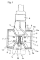
- Fig. 1 is a schematic cross-section drawing showing an embodiment of a magnetron according to the present invention.
- Fig. 2 (a) is a schematic cross-section drawing showing a magnetron, according to the present invention, before elements are loosely secured.
- Fig. 2 (b) is a schematic cross-section drawing showing a magnetron, according to the present invention, after elements are loosely secured.
- Fig. 3 (a) shows a state of a magnetron, according to another embodiment of the present invention, before elements are loosely secured.
- Fig. 3 (b) is shows a state of a magnetron, according to another embodiment of the present invention, after elements are loosely secured.
- Fig. 4 is a schematic cross-section drawing showing an example of a conventional magnetron.
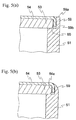
- Fig. 5 (a) is a cross-section drawing of a conventional magnetron before tight welding is performed.
- Fig. 5 (b) is a cross-section drawing of a conventional magnetron after tight welding is performed.
- a magnetron according to an embodiment of the present invention includes an anode vacuum container 1.
- a cathode 2 is disposed along the central axis of container 1.
- An antenna 3 extracts microwaves generated in a hollow manner.
- the magnetron further includes an antenna ceramic 4 and cathode supports 5a, 5b.
- Anode vacuum container 1 includes a cylindrical anode cylinder 6. A plurality of vanes 7 are arranged radially inside anode cylinder 6. Magnetic pieces 8, 9 are disposed at the upper and lower openings of anode cylinder 6. Metal containers 10, 11 cover the upper surfaces of magnetic pieces 8, 9.
- Cathode 2 includes an end hat 12 secured to the end of cathode support 5a.
- a top hat 13 is secured to the end of cathode support 5b, which passes through end hat 12.
- a filament 14 is wrapped around cathode support 5b between top hat 13 and end hat 12.
- anode cylinder 6 is prepared as a cylindrical material with upper and lower openings from the ends of which are projected ring-shaped thin end sections 6a.
- Magnetic piece 8 and metal container 10, having a bent outer perimeter, are placed, in that order, on a shelf 15, formed on the inner side of thin end section 6a.
- a projection tool 17, on which a projection 16 having a predetermined shape, is placed at the outer side of anode cylinder 6, opposite from thin end section 6a.
- projection tool 17 is impacted on thin end section 6a of anode cylinder 6, forming an inward projection 18 on thin end section 6a.
- Inward projection 18 abuts outer perimeter bend 10a. It would be desirable to form at least three inward projections 18 along the perimeter so that metal container 10 stays centered.
- thin end section 6a and outer bend 10a are tightly welded together. This tight welding is performed, for example, by using electron beam welding.
- the tight welding operation is performed by loosely securing metal container 10 using projection 18 of thin end section 6a.
- a tight seal is formed and maintained between anode cylinder 6 and metal container 10.
- Metal container 10 is supported by laterally projecting projection 18.
- Metal container 10 is loosely secured in a reliable manner even if the end surface of projection 18, formed on thin end section 6a, is positioned lower than the upper surface of metal container 10. As a result, the metal container is loosely secured even without increasing the height of anode cylinder 6. This reduces the material costs for anode cylinder 6.
- the projection is formed by first positioning the magnetic piece and the metal container and then using the projection tool placed outside the thin end section of the anode cylinder.
- the present invention is not restricted to this specific embodiment. It would also be possible, for example, to first place the magnetic piece at an open end of the anode cylinder, on which is formed a predetermined inward projection positioned opposite from the thin end section. Then, the metal container would be positioned, and the outer perimeter bend of the metal container would be pressed into the projection, thus assembling the elements before making the tight weld.
- Fig. 3(a) it is also possible to place, on the opening of anode cylinder 6, magnetic piece 8 and a metal container 21, on which is formed a predetermined number of holes 22 along outer perimeter bend 21a. Then, projection tool 17 is placed outside of anode cylinder 6, opposite from thin end section 6a.
- projection tool 17 is aligned with hole 22 and impacted against thin end section 6a of anode cylinder 6.
- Thin end section 6a forms inward projection 18.
- Inward projection 18 is inserted into hole 22. It is desirable to have at least three inward projections 18 and holes 22 engaged at the same time along the perimeter so that metal container 21 stays centered. Then, thin end section 6a and outer perimeter bend 21 a are tightly welded.
- inward projection 18 of thin end section 6a loosely secures metal container 21, thus keeping metal container 21 centered, allowing accurate welding of thin end section 6a and metal container 21.
- This provides a tight bond between anode cylinder 6 and metal container 21.
- Metal container 21 is supported by laterally projecting inward projection 18.
- the outer perimeter bend of the metal container is loosely secured by a predetermined number of projections projecting inward from the thin end section of the anode cylinder.
- the present invention is not restricted to this, however, and it would also be possible to loosely secure the outer perimeter bend of the metal container using a ring-shaped projection projecting inward from the thin end section of the anode cylinder.
- the present invention allows improved welding for the assembly of the main magnetron unit. Additional, the present invention provides a tight bond between the anode cylinder and the metal container.
- a magnetron has an anode cylinder, a plurality of vanes arranged radially within the anode cylinder, a magnetic piece disposed at an open end section of the anode cylinder, an anode vacuum container including a metal container disposed to cover an upper surface of the magnetic piece, a cathode disposed along a central axis of the vacuum container, and an antenna externally discharging microwaves.
- the magnetic piece and the metal container are placed, in that order, on a shelf formed inwardly on a thin end section projecting from the open end section of the anode cylinder.
Landscapes
- Engineering & Computer Science (AREA)
- Manufacturing & Machinery (AREA)
- Power Engineering (AREA)
- Microwave Tubes (AREA)
Abstract
Description
- The present invention relates to a method for making magnetrons. More specifically, the present invention relates to a method for making magnetrons used in radars, microwave heating devices, e.g., microwave ovens, or the like.
- Referring to Fig. 4, a conventional magnetron includes a plurality of
vanes 52 formed within acylindrical anode cylinder 51. Ananode vacuum container 55 includes amagnetic piece 53 and ametal container 54 disposed at the open end section of theanode cylinder 51. Acathode 57, disposed along the center axis ofvacuum container 55, includes atop hat 56a, anend hat 56b, and afilament 56c. Anantenna 58 extracts a microwave, e.g., at 2450 MHZ, generated in the hollow space. In this magnetron, the thermoelectrons discharged byfilament 56c spin inside the active space formed betweenvanes 52 andfilament 56c, generating a microwave. This microwave, flowing along avane 52, is transferred toantenna 58 connected to vain 52. The microwave is then discharged externally throughantenna 58. -
Anode cylinder 51 andmetal container 54 are bonded by tightly weldingthin end section 59 ofanode cylinder 51. Referring to Fig. 5(a), before the welding operation,thin end section 59 ofanode cylinder 51 has a roughly even thickness betweenend 59a andbase section 59b.Magnetic piece 53 andmetal container 54 are placed on an inner shelf ofthin end section 59. - Referring to Figs. 4 and 5(b),
thin end section 59 ofanode cylinder 51 is melted by welding to form a tight bond withouter perimeter bend 54a ofmetal container 54. - If a slight gap forms between the inner wall surface of
thin end section 59 ofanode cylinder 51 andouter perimeter bend 54a ofmetal container 54 due to dimensional tolerances, misalignment of the parts, or the like, this gap will remain, even after the tight welding. This can lead to reduced sealing properties. Discarding such assemblies results in increases material costs, while performing repairs of these assemblies increases the number of steps involved in the procedure. - To prevent these gaps, the parts may be formed with shapes that provide alignment relative to each other. If alignment between the parts is not possible, dedicated tools or equipment may be used to secure the parts while welding. However, with each of these methods there is an increase in production costs.
- It is an object of the present invention to provide a method for making a magnetron which overcomes the foregoing problems.
- More specifically, it is an object of the present invention to provide a method for making magnetrons that easily improves the quality of the tight welding operation.
- Briefly stated, the present invention provides amagnetron having an anode cylinder, a plurality of vanes arranged radially within the anode cylinder, a magnetic piece disposed at an open end section of the anode cylinder, an anode vacuum container including a metal container disposed to cover an upper surface of the magnetic piece, a cathode disposed along a central axis of the vacuum container, and an antenna externally discharging microwaves. The magnetic piece and the metal container are placed, in that order, on a shelf formed inwardly on a thin end section projecting from the open end section of the anode cylinder. When tightly welding the thin end section, a predetermined number of projections, projecting inwardly from the thin end section ofthe anode cylinder, loosely secure an outer perimeter bend of the metal container. The metal container is then accurately tightly weld to the anode cylinder without the metal container shifting off-center.
- According to an embodiment of the present invention, a method for making magnetrons includes a magnetron having an anode cylinder, a plurality of vanes arranged radially within the anode cylinder, a magnetic piece disposed at an open end section of the anode cylinder, an anode vacuum container including a metal container disposed to cover an upper surface of the magnetic piece, a cathode disposed along a central axis of the vacuum container, and an antenna externally discharging microwaves. The magnetic piece and the metal container are placed, in that order, on a shelf formed inwardly on the thin end section projecting from the open end section of the anode cylinder. When tightly welding the thin end section, a predetermined number of projections projecting inwardly from the thin end section of the anode cylinder is used to loosely secure an outer perimeter bend of the metal container.
- According to another embodiment of the present invention, a method for making magnetrons includes providing a magnetron having an anode cylinder, a plurality of vanes arranged radially within the anode cylinder, a magnetic piece disposed at an open end section of the anode cylinder, an anode vacuum container including a metal container disposed to cover an upper surface of the magnetic piece, a cathode disposed along a central axis of the vacuum container, and an antenna externally discharging microwaves. The magnetic piece and the metal container are placed, in that order, on a shelf formed inwardly on the thin end section projecting from the open end section of the anode cylinder. When tightly welding the thin end section, a ring-shaped projection, projecting inward from the thin end section of the anode cylinder, is used to loosely secure an outer perimeter bend of the metal container.
- The above, and other objects, features and advantages of the present invention will become apparent from the following description read in conjunction with the accompanying drawings, in which like reference numerals designate the same elements.
- Fig. 1 is a schematic cross-section drawing showing an embodiment of a magnetron according to the present invention.
- Fig. 2 (a) is a schematic cross-section drawing showing a magnetron, according to the present invention, before elements are loosely secured.
- Fig. 2 (b) is a schematic cross-section drawing showing a magnetron, according to the present invention, after elements are loosely secured.
- Fig. 3 (a) shows a state of a magnetron, according to another embodiment of the present invention, before elements are loosely secured.
- Fig. 3 (b) is shows a state of a magnetron, according to another embodiment of the present invention, after elements are loosely secured.
- Fig. 4 is a schematic cross-section drawing showing an example of a conventional magnetron.
- Fig. 5 (a) is a cross-section drawing of a conventional magnetron before tight welding is performed.
- Fig. 5 (b) is a cross-section drawing of a conventional magnetron after tight welding is performed.
- Referring to the attached drawings, the following is a description of a method for making magnetrons according to the present invention.
- Referring to Fig. 1, a magnetron according to an embodiment of the present invention includes an anode vacuum container 1. A
cathode 2 is disposed along the central axis of container 1. An antenna 3 extracts microwaves generated in a hollow manner. The magnetron further includes an antenna ceramic 4 and cathode supports 5a, 5b. - Anode vacuum container 1 includes a
cylindrical anode cylinder 6. A plurality ofvanes 7 are arranged radially insideanode cylinder 6.Magnetic pieces anode cylinder 6.Metal containers magnetic pieces - Cathode 2 includes an
end hat 12 secured to the end ofcathode support 5a. Atop hat 13 is secured to the end ofcathode support 5b, which passes throughend hat 12. Afilament 14 is wrapped aroundcathode support 5b betweentop hat 13 andend hat 12. - Thin
end section sections 6a, projecting from the ends of the upper and lower openings ofanode cylinder 6, are tightly welded toouter perimeter bends metal containers metal containers anode cylinder 6. - Next, the procedure for tightly welding outer perimeter bends 10a, 11 a of
thin end sections 6a will be described. To facilitate the discussion, the tight welding betweenthin end section 6a, projecting from the end of the upper opening ofanode cylinder 6, toouter perimeter bend 10a will be described. - Referring now to Fig. 2(a),
anode cylinder 6 is prepared as a cylindrical material with upper and lower openings from the ends of which are projected ring-shapedthin end sections 6a.Magnetic piece 8 andmetal container 10, having a bent outer perimeter, are placed, in that order, on ashelf 15, formed on the inner side ofthin end section 6a. Then, aprojection tool 17, on which aprojection 16 having a predetermined shape, is placed at the outer side ofanode cylinder 6, opposite fromthin end section 6a. - Referring to Fig. 2(b),
projection tool 17 is impacted onthin end section 6a ofanode cylinder 6, forming aninward projection 18 onthin end section 6a.Inward projection 18 abutsouter perimeter bend 10a. It would be desirable to form at least threeinward projections 18 along the perimeter so thatmetal container 10 stays centered. Next,thin end section 6a andouter bend 10a are tightly welded together. This tight welding is performed, for example, by using electron beam welding. - In this embodiment of the present invention, the tight welding operation is performed by loosely securing
metal container 10 usingprojection 18 ofthin end section 6a. This preventsmetal container 10 from becoming off-center, allowing accurate welding ofmetal container 10 tothin end section 6a. As a result, a tight seal is formed and maintained betweenanode cylinder 6 andmetal container 10.Metal container 10 is supported by laterally projectingprojection 18.Metal container 10 is loosely secured in a reliable manner even if the end surface ofprojection 18, formed onthin end section 6a, is positioned lower than the upper surface ofmetal container 10. As a result, the metal container is loosely secured even without increasing the height ofanode cylinder 6. This reduces the material costs foranode cylinder 6. - In this embodiment of the present invention, the projection is formed by first positioning the magnetic piece and the metal container and then using the projection tool placed outside the thin end section of the anode cylinder. However, the present invention is not restricted to this specific embodiment. It would also be possible, for example, to first place the magnetic piece at an open end of the anode cylinder, on which is formed a predetermined inward projection positioned opposite from the thin end section. Then, the metal container would be positioned, and the outer perimeter bend of the metal container would be pressed into the projection, thus assembling the elements before making the tight weld.
- Referring now to Fig. 3(a), it is also possible to place, on the opening of
anode cylinder 6,magnetic piece 8 and ametal container 21, on which is formed a predetermined number ofholes 22 alongouter perimeter bend 21a. Then,projection tool 17 is placed outside ofanode cylinder 6, opposite fromthin end section 6a. - Referring to Fig. 3(b),
projection tool 17 is aligned withhole 22 and impacted againstthin end section 6a ofanode cylinder 6.Thin end section 6a formsinward projection 18.Inward projection 18 is inserted intohole 22. It is desirable to have at least threeinward projections 18 and holes 22 engaged at the same time along the perimeter so thatmetal container 21 stays centered. Then,thin end section 6a and outer perimeter bend 21 a are tightly welded. - In this embodiment of the present invention,
inward projection 18 ofthin end section 6a loosely securesmetal container 21, thus keepingmetal container 21 centered, allowing accurate welding ofthin end section 6a andmetal container 21. This provides a tight bond betweenanode cylinder 6 andmetal container 21.Metal container 21 is supported by laterally projectinginward projection 18. Thus, as with the embodiment described above, loose securing is achieved without increasing the height ofanode cylinder 6. As a result, the material costs foranode cylinder 6 are reduced. - In these embodiments, the outer perimeter bend of the metal container is loosely secured by a predetermined number of projections projecting inward from the thin end section of the anode cylinder. The present invention is not restricted to this, however, and it would also be possible to loosely secure the outer perimeter bend of the metal container using a ring-shaped projection projecting inward from the thin end section of the anode cylinder.
- As described above, the present invention allows improved welding for the assembly of the main magnetron unit. Additional, the present invention provides a tight bond between the anode cylinder and the metal container.
- Having described preferred embodiments of the invention with reference to the accompanying drawings, it is to be understood that the invention is not limited to those precise embodiments, and that various changes and modifications may be effected therein by one skilled in the art without departing from the scope or spirit of the invention as defined in the appended claims.
- A magnetron has an anode cylinder, a plurality of vanes arranged radially within the anode cylinder, a magnetic piece disposed at an open end section of the anode cylinder, an anode vacuum container including a metal container disposed to cover an upper surface of the magnetic piece, a cathode disposed along a central axis of the vacuum container, and an antenna externally discharging microwaves. The magnetic piece and the metal container are placed, in that order, on a shelf formed inwardly on a thin end section projecting from the open end section of the anode cylinder. When tightly welding the thin end section, a predetermined number of projections, projecting inwardly from the thin end section of the anode cylinder, loosely secure an outer perimeter bend of the metal container. The metal container is then accurately tightly weld to the anode cylinder without the metal container shifting off-center.
Claims (17)
- A method for making amagnetron wherein said magnetron comprises:an anode cylinder;a plurality of vanes arranged radially within said anode cylinder;a magnetic piece disposed at an open end section of said anode cylinder;an anode vacuum container, including a metal container covering an upper surface of said magnetic piece;a cathode disposed along a central axis of said vacuum container; andan antenna externally discharging microwaves;said method having steps comprising:placing said magnetic piece and said metal container, in that order, on a shelf formed inwardly on a thin end section projecting from said open end section of said anode cylinder;forming a predetermined number of projections projecting inwardly from said thin end section of said anode cylinder, whereby said metal container is loosely secured; andtightly welding said thin end section with said metal container.
- The method for making magnetrons as described in claim 1, wherein an outer perimeter of said metal container is bent inward to form an outer perimeter bend, covering a substantial section of end portions of said magnetic piece.
- The method for making magnetrons as described in claim 2, wherein said predetermined number of projections are formed after said metal piece and said metal container have been installed by using a projection tool disposed outside said thin end section of said anode cylinder.
- The method for making magnetrons as described in claim 2, wherein:said predetermined number of projections are formed before said metal container is installed; andloosely securing said metal container by pushing said outer perimeter bend of said metal container into said predetermined number of projections.
- The method for making magnetrons as described in claim 2, wherein said predetermined number of projections are inserted into a predetermined number of holes disposed on said outer perimeter bend of said metal container.
- The method for making magnetrons as described in claim 3, wherein said predetermined number of projections are inserted into a predetermined number of holes disposed on said outer perimeter bend of said metal container.
- The method for making magnetrons as described in claim 2, wherein an end surface of said thin end section formed as a projection is formed lower than an upper surface of said metal container.
- The method for making magnetrons as described in claim 3, wherein said predetermined number of projections are inserted into a predetermined number of holes disposed on said outer perimeter bend of said metal container.
- The method for making magnetrons as described in claim 4, wherein said predetermined number of projections are inserted into a predetermined number of holes disposed on said outer perimeter bend of said metal container.
- The method for making magnetrons as described in claim 5, wherein said predetermined number of projections are inserted into a predetermined number of holes disposed on said outer perimeter bend of said metal container.
- A method for making magnetrons including, said magnetrons comprising:an anode cylinder;a plurality of vanes arranged radially within said anode cylinder;a magnetic piece disposed at an open end section of said anode cylinder;an anode vacuum container including a metal container disposed to cover an upper surface of said magnetic piece;a cathode disposed along a central axis of said vacuum container; andan antenna externally discharging microwaves;said method having steps comprising:placing said magnetic piece and said metal container, in that order, on a shelf formed inwardly on a thin end section projecting from said open end section of said anode cylinder; andforming a substantially ring-shaped projection, projecting inwardly from said thin end section of said anode cylinder, whereby said metal container is loosely secured; andtightly welding said thin end section with said metal container.
- The method for making magnetrons as described in claim 11, wherein an outer perimeter of said metal container is bent inward to form an outer perimeter bend, covering a substantial section of end portions of said magnetic piece.
- The method for making magnetrons as described in claim 12, wherein said ring-shaped projection is formed after said magnetic piece and said metal container have been installed by using a projection tool disposed outside said thin end section of said anode cylinder.
- The method for making magnetrons as described in claim 12, wherein:said ring-shaped projections is formed before said metal container is installed; andloosely securing said metal container by pushing said outer perimeter bend of said metal container into said ring-shaped projection.
- The method for making magnetrons as described in claim 12, wherein an end surface of said thin end section formed as a projection is formed lower than an upper surface of said metal container.
- The method for making magnetrons as described in claim 13, wherein an end surface of said thin end section formed as a projection is formed lower than an upper surface of said metal container.
- The method for making magnetrons as described in claim 14, wherein an end surface of said thin end section formed as a projection is formed lower than an upper surface of said metal container.
Applications Claiming Priority (2)
| Application Number | Priority Date | Filing Date | Title |
|---|---|---|---|
| JP2000390962A JP2002190257A (en) | 2000-12-22 | 2000-12-22 | Manufacturing method of magnetron |
| JP2000390962 | 2000-12-22 |
Publications (1)
| Publication Number | Publication Date |
|---|---|
| EP1217641A1 true EP1217641A1 (en) | 2002-06-26 |
Family
ID=18857216
Family Applications (1)
| Application Number | Title | Priority Date | Filing Date |
|---|---|---|---|
| EP01130192A Withdrawn EP1217641A1 (en) | 2000-12-22 | 2001-12-19 | Method for making magnetrons |
Country Status (5)
| Country | Link |
|---|---|
| US (1) | US6729926B2 (en) |
| EP (1) | EP1217641A1 (en) |
| JP (1) | JP2002190257A (en) |
| KR (1) | KR100447809B1 (en) |
| CN (1) | CN1155983C (en) |
Families Citing this family (8)
| Publication number | Priority date | Publication date | Assignee | Title |
|---|---|---|---|---|
| CN100432538C (en) * | 2003-04-11 | 2008-11-12 | 乐金电子(天津)电器有限公司 | Combination method of magnetron element for microwave oven and its combination material |
| WO2011094577A2 (en) | 2010-01-29 | 2011-08-04 | Micronics, Inc. | Sample-to-answer microfluidic cartridge |
| WO2014100732A1 (en) | 2012-12-21 | 2014-06-26 | Micronics, Inc. | Fluidic circuits and related manufacturing methods |
| JP2016509206A (en) | 2012-12-21 | 2016-03-24 | マイクロニクス, インコーポレイテッド | Portable fluorescence detection system and microassay cartridge |
| US10518262B2 (en) | 2012-12-21 | 2019-12-31 | Perkinelmer Health Sciences, Inc. | Low elasticity films for microfluidic use |
| CN105189784B (en) | 2013-05-07 | 2020-06-30 | 珀金埃尔默健康科学有限公司 | Device for preparing and analyzing nucleic acids |
| CA2911303C (en) | 2013-05-07 | 2021-02-16 | Micronics, Inc. | Methods for preparation of nucleic acid-containing samples using clay minerals and alkaline solutions |
| WO2014182844A1 (en) | 2013-05-07 | 2014-11-13 | Micronics, Inc. | Microfluidic devices and methods for performing serum separation and blood cross-matching |
Citations (4)
| Publication number | Priority date | Publication date | Assignee | Title |
|---|---|---|---|---|
| JPS60117527A (en) * | 1983-11-30 | 1985-06-25 | Hitachi Ltd | magnetron |
| JPS63146326A (en) * | 1986-07-28 | 1988-06-18 | Toshiba Corp | Magnetron for electronic oven and manufacture thereof |
| JPH0261933A (en) * | 1988-08-29 | 1990-03-01 | Matsushita Electron Corp | Manufacture of anode assembly for magnetron |
| JPH05275019A (en) * | 1992-03-27 | 1993-10-22 | Sanyo Electric Co Ltd | Magnetron |
Family Cites Families (7)
| Publication number | Priority date | Publication date | Assignee | Title |
|---|---|---|---|---|
| US3610870A (en) * | 1968-03-13 | 1971-10-05 | Hitachi Ltd | Method for sealing a semiconductor element |
| US4495397A (en) * | 1980-02-11 | 1985-01-22 | Paul Opprecht | Projection for resistance welding of soft metals |
| JPS6068180A (en) * | 1983-09-26 | 1985-04-18 | Mitsui Petrochem Ind Ltd | Welding method of metallic material having insulating layer |
| DE3933277A1 (en) * | 1989-02-08 | 1990-08-09 | Nippon Dia Clevite Co | METHOD FOR JOINING METAL PARTS |
| US5168142A (en) * | 1991-05-28 | 1992-12-01 | Ford Motor Company | Method for fabricating a clutch cylinder-drum assembly |
| CA2232480C (en) * | 1995-09-18 | 2001-07-03 | Honda Giken Kogyo Kabushiki Kaisha | Process for lap-bonding of two metal members having different melting points |
| JP2002197984A (en) * | 2000-12-26 | 2002-07-12 | Sanyo Electric Co Ltd | Manufacturing method of magnetron |
-
2000
- 2000-12-22 JP JP2000390962A patent/JP2002190257A/en active Pending
-
2001
- 2001-11-28 KR KR10-2001-0074673A patent/KR100447809B1/en not_active Expired - Fee Related
- 2001-12-12 US US10/020,766 patent/US6729926B2/en not_active Expired - Fee Related
- 2001-12-19 EP EP01130192A patent/EP1217641A1/en not_active Withdrawn
- 2001-12-20 CN CNB011447036A patent/CN1155983C/en not_active Expired - Fee Related
Patent Citations (4)
| Publication number | Priority date | Publication date | Assignee | Title |
|---|---|---|---|---|
| JPS60117527A (en) * | 1983-11-30 | 1985-06-25 | Hitachi Ltd | magnetron |
| JPS63146326A (en) * | 1986-07-28 | 1988-06-18 | Toshiba Corp | Magnetron for electronic oven and manufacture thereof |
| JPH0261933A (en) * | 1988-08-29 | 1990-03-01 | Matsushita Electron Corp | Manufacture of anode assembly for magnetron |
| JPH05275019A (en) * | 1992-03-27 | 1993-10-22 | Sanyo Electric Co Ltd | Magnetron |
Non-Patent Citations (4)
| Title |
|---|
| PATENT ABSTRACTS OF JAPAN vol. 009, no. 274 (E - 354) 31 October 1985 (1985-10-31) * |
| PATENT ABSTRACTS OF JAPAN vol. 012, no. 403 (E - 674) 26 October 1988 (1988-10-26) * |
| PATENT ABSTRACTS OF JAPAN vol. 014, no. 234 (E - 0929) 17 May 1990 (1990-05-17) * |
| PATENT ABSTRACTS OF JAPAN vol. 018, no. 047 (E - 1496) 25 January 1994 (1994-01-25) * |
Also Published As
| Publication number | Publication date |
|---|---|
| CN1155983C (en) | 2004-06-30 |
| KR20020051824A (en) | 2002-06-29 |
| JP2002190257A (en) | 2002-07-05 |
| KR100447809B1 (en) | 2004-09-08 |
| US6729926B2 (en) | 2004-05-04 |
| US20020081934A1 (en) | 2002-06-27 |
| CN1360329A (en) | 2002-07-24 |
Similar Documents
| Publication | Publication Date | Title |
|---|---|---|
| US4705989A (en) | Magnetron with a ceramic stem having a cathode support structure | |
| US6729926B2 (en) | Method for making magnetrons | |
| US5635798A (en) | Magnetron with reduced dark current | |
| CA1154493A (en) | Envelope for flat panel display devices | |
| EP1282150B1 (en) | Photomultiplier tube | |
| US5090613A (en) | Method of manufacturing an anode assembly of a magnetron | |
| EP1304718B1 (en) | Photomultiplier tube and production method therefor | |
| EP0871196B1 (en) | Magnetron apparatus and manufacturing method for the same | |
| US6572426B1 (en) | Method for producing x-ray tube | |
| EP0696048B1 (en) | Electron beam tubes | |
| US4996458A (en) | Shadow mask assembly for color cathode ray tube | |
| KR20010014995A (en) | Cathode ray tube | |
| US6288480B1 (en) | Color cathode ray tube | |
| KR100291968B1 (en) | Cathode ray tube and method of manufacturing the same | |
| JP2000260343A (en) | Color cathode ray tube | |
| JP3069065B2 (en) | Magnetron | |
| KR100270880B1 (en) | Magnetron anode assembly | |
| JP2001006566A (en) | Magnetron | |
| JPH11307000A (en) | Magnetron | |
| JPS6298537A (en) | Magnetron for microwave oven | |
| JPH0850999A (en) | Beam duct | |
| JPS6323868Y2 (en) | ||
| JP2000003676A (en) | Variable oscillation frequency magnetron | |
| KR200205837Y1 (en) | Eccentric lock for center lead of magnetron | |
| GB2306768A (en) | Magnetron antenna feeders |
Legal Events
| Date | Code | Title | Description |
|---|---|---|---|
| PUAI | Public reference made under article 153(3) epc to a published international application that has entered the european phase |
Free format text: ORIGINAL CODE: 0009012 |
|
| AK | Designated contracting states |
Kind code of ref document: A1 Designated state(s): AT BE CH CY DE DK ES FI FR GB GR IE IT LI LU MC NL PT SE TR |
|
| AX | Request for extension of the european patent |
Free format text: AL;LT;LV;MK;RO;SI |
|
| 17P | Request for examination filed |
Effective date: 20021031 |
|
| AKX | Designation fees paid |
Designated state(s): AT BE CH CY DE DK ES FI FR GB GR IE IT LI LU MC NL PT SE TR |
|
| 17Q | First examination report despatched |
Effective date: 20050322 |
|
| STAA | Information on the status of an ep patent application or granted ep patent |
Free format text: STATUS: THE APPLICATION IS DEEMED TO BE WITHDRAWN |
|
| 18D | Application deemed to be withdrawn |
Effective date: 20051005 |