EP1217444A1 - A belt drive rack and tank photographic processing apparatus - Google Patents
A belt drive rack and tank photographic processing apparatus Download PDFInfo
- Publication number
- EP1217444A1 EP1217444A1 EP01204804A EP01204804A EP1217444A1 EP 1217444 A1 EP1217444 A1 EP 1217444A1 EP 01204804 A EP01204804 A EP 01204804A EP 01204804 A EP01204804 A EP 01204804A EP 1217444 A1 EP1217444 A1 EP 1217444A1
- Authority
- EP
- European Patent Office
- Prior art keywords
- belt
- photosensitive material
- processing
- tank
- processing channel
- Prior art date
- Legal status (The legal status is an assumption and is not a legal conclusion. Google has not performed a legal analysis and makes no representation as to the accuracy of the status listed.)
- Withdrawn
Links
- 239000000463 material Substances 0.000 claims abstract description 50
- 238000000034 method Methods 0.000 claims description 8
- 239000012530 fluid Substances 0.000 abstract 1
- 239000004033 plastic Substances 0.000 description 2
- 239000000126 substance Substances 0.000 description 2
- 230000002411 adverse Effects 0.000 description 1
- 238000004061 bleaching Methods 0.000 description 1
- 150000001875 compounds Chemical class 0.000 description 1
- 238000007599 discharging Methods 0.000 description 1
- 238000001035 drying Methods 0.000 description 1
- 239000000839 emulsion Substances 0.000 description 1
- 239000007788 liquid Substances 0.000 description 1
- 230000002035 prolonged effect Effects 0.000 description 1
- 230000003134 recirculating effect Effects 0.000 description 1
- 238000005406 washing Methods 0.000 description 1
Images

Classifications
-
- G—PHYSICS
- G03—PHOTOGRAPHY; CINEMATOGRAPHY; ANALOGOUS TECHNIQUES USING WAVES OTHER THAN OPTICAL WAVES; ELECTROGRAPHY; HOLOGRAPHY
- G03D—APPARATUS FOR PROCESSING EXPOSED PHOTOGRAPHIC MATERIALS; ACCESSORIES THEREFOR
- G03D3/00—Liquid processing apparatus involving immersion; Washing apparatus involving immersion
- G03D3/08—Liquid processing apparatus involving immersion; Washing apparatus involving immersion having progressive mechanical movement of exposed material
- G03D3/12—Liquid processing apparatus involving immersion; Washing apparatus involving immersion having progressive mechanical movement of exposed material for plates, films or prints spread onto belt conveyors
Definitions
- the processing of photosensitive or photographic material or film involves a series of steps such as developing, bleaching, fixing, washing and drying. These steps lend themselves to mechanization by conveying a continuous web of film or cut sheets of film or photographic paper sequentially through a series of stations or tanks, each one containing a different processing solution or liquid appropriate to the process step at that station.
Landscapes
- Physics & Mathematics (AREA)
- General Physics & Mathematics (AREA)
- Photographic Processing Devices Using Wet Methods (AREA)
- Devices For Conveying Motion By Means Of Endless Flexible Members (AREA)
Abstract
A belt driven rack (5) and tank (7) processor includes a belt for driving photosensitive material through a relatively thin processing channel (9) formed by the rack and tank of the processor. The belt travels around a core that displaces fluid within the apparatus so as to provide for a low volume processor. The processor further includes spring loaded engaging rollers which facilitate the conveyance of cut sheets through the processor.
Description
- The present invention relates to the field of photography, and more particularly to a belt drive rack and tank photographic or photosensitive material processing apparatus.
- The processing of photosensitive or photographic material or film involves a series of steps such as developing, bleaching, fixing, washing and drying. These steps lend themselves to mechanization by conveying a continuous web of film or cut sheets of film or photographic paper sequentially through a series of stations or tanks, each one containing a different processing solution or liquid appropriate to the process step at that station.
- There are various sizes of photographic material or film processing apparatuses, i.e., large photofinishing apparatuses and microlabs. A large photofinishing apparatus utilizes tanks that contain approximately 100 liters of each processing solution. A small photofinishing apparatus or microlab utilizes tanks that might contain less than 10 liters of processing solution.
- U.S. Patent No. 5,432,581 describes a rack and tank arrangement that forms part of a low volume photographic material processing apparatus. The arrangement of U.S. Patent No. 5,432,581 includes an inner rack section and an outer tank section that are easily separated. The rack and tank of U.S. Patent No. 5,432,581 are relatively dimensioned so as to define a channel for holding a small volume of processing solution and permitting a passage of photosensitive material therethrough. In the apparatus of U.S. Patent No. 5,432,581, a pair of input rollers are placed at an input end of the apparatus to introduce processing material into the apparatus, and a pair of output rollers are placed at an output end of the apparatus to discharge the processed photosensitive material from the apparatus. Furthermore, in addition to the input and output pair of rollers, at least three drive rollers are positioned along the processing channel, and gears are attached to designated drive rollers to drive photosensitive material along the channel. The increased use of drive rollers and gears as shown in, for example U.S. Patent No. 5,432, 581, adds cost and complexity to the apparatus. Also, the increased numbers of rollers and gears adversely affects the reliability of the apparatus since it increases the number of parts that are needed to be repaired. Furthermore, in order to properly convey cut sheets, the drive rollers need to be appropriately spaced which again, tends to increase the amount of drive rollers needed.
- The present invention provides for a belt drive rack and tank processing apparatus for processing photographic material which minimizes the amount of rollers and gears necessary for the conveyance of photosensitive material. The belt drive rack and tank apparatus of the present invention requires less parts than a conventional rack and tank arrangement and facilitates the conveyance of cut sheets.
- The present invention relates to an apparatus for processing photosensitive material. The apparatus comprises a tank and a rack that is adapted to be placed in the tank. The rack and the tank are relatively dimensioned so as to provide a relatively small narrow processing channel therebetween for holding a processing solution and permitting a photosensitive material to pass therethrough. The apparatus further includes a belt that extends along at least a portion of the processing channel. The belt has an outer surface which faces a photosensitive material in the processing channel and the belt is further adapted to be driven so as to convey photosensitive material along the processing channel.
- The present invention further relates to a method of processing photosensitive material. The method comprises the step of introducing a photosensitive material to be processed into a relatively thin processing channel that is defined between a tank and a rack placed in the tank. The rack has a belt that extends along at least a portion of the processing channel. The method further comprises the step of conveying the photosensitive material to be processed through the processing channel by driving the belt.
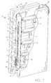
- Fig. 1 is a perspective view of a belt drive rack and tank photographic processor in accordance with the present invention; and
- Fig. 2 is a side view of the rack and tank photographic processor of Fig. 1.
-
- Referring now to the drawings, wherein like references numerals represent identical or corresponding parts throughout the several views, Fig. 1 shows a perspective view of a low volume belt drive rack and tank apparatus or processor 3 in accordance with the present invention. As illustrated in Fig. 1, a
rack 5 is designed so as to be easily inserted and/or removed from atank 7. Rack 5 andtank 7 form low volume processor or apparatus 3. In the view of Fig. 1, part ofrack 7 is cut away so as to view the interior of processor 3. - When
rack 5 is inserted withintank 7, a space which defines a narrow processing channel 9 (Fig. 2) is formed. Rack 5 andtank 7 are designed in a manner which minimizes the volume ofprocessing channel 9.Processing channel 9 defines a path for the passage of photosensitive material or film in the form of a continuous web or cut sheets therethrough. - In the apparatus illustrated in Fig. 1,
rack 7 includesslot nozzles 11 which are provided alongprocessing channel 9. Processing solution is supplied from a known source toprocessing solution inlets 14 and thereafter applied to photosensitive material passing throughprocessing channel 9, by way ofslot nozzles 11.Slot nozzles 11 essentially extend through the entire width ofprocessing channel 9. - In a known manner, processor or processing apparatus 3 includes a discharge opening in the bottom of the apparatus for discharging processing solution. This processing solution would be lead in a known manner by way of a recirculating pump to a manifold and filter arrangement. The filter arrangement would be connected to a heat exchanger which in a known manner can provide recirculated processing solution as needed back to processing apparatus 3 (see for example, U.S. Patent No. 5,432,581). As also described in U.S. Patent No. 5,432,581, processing chemicals can be placed in metering pumps which are used to provide the correct amount of chemicals for introduction to
processing solution inlet 14. - As shown in Fig. 1,
rack 5 includes atop roller 19 and abottom roller 21. In a first feature of the present invention, anendless belt 23 is wrapped around top andbottom rollers Belt 23 is preferably made of a flexible material such as rubber, plastic or a plastic or rubber compound. As shown more clearly in Fig. 2,processing channel 9 is defined by an interior surface ofrack 7 and an outer surface ofbelt 23.Belt 23 extends along at least a portion ofprocessing channel 9 and basically defines an outer periphery ofrack 5. One of the top orbottom rollers endless belt 23. In the embodiment of Fig. 1,top roller 19 is shown attached to agear 25, that preferably can be driven by a driving member in the form of, for example, a motor and chain drive. However, the present invention is not limited thereto, and any of therollers - As further shown in Fig. 1,
tank 7 includes a plurality of freely rotatable spring loadedengaging rollers 17 which extend alongprocessing channel 9 and face the outer surface ofbelt 23. Each ofengaging rollers 17 is spring loaded towardsbelt 23 and are spaced at a desired distance to permit the conveyance of cut sheets throughprocessing channel 9. As shown particularly in Fig. 2, hinged springengaging rollers 17 can be preferably positioned withincutouts 17a intank 7. - As also shown in Figs. 1 and 2, a
core 27 is provided between top andbottom rollers belt 23. Core 27 is effective as a back surface forbelt 23. Core 27 further takes up space within processing apparatus 3 so as to minimize solution volume within apparatus 3 and thus, provide for a low volume processing apparatus. - Therefore, during use of processing apparatus 3, photosensitive material or film is introduced to processing
channel 9 via, for example,inlet 29. When the photosensitive material is introduced,belt 23 is driven by way of, for example,drive roller 19. The driving ofbelt 23 causes the conveyance of the photosensitive material along adownward portion 9a ofprocessing channel 9 by way of the friction between the photosensitive material andbelt 23. As the photosensitive material is conveyed alongprocessing channel 9, an emulsion surface of the photosensitive material facesslot nozzles 11 which impinge the photosensitive material with processing solution supplied viaprocessing solution inlet 14. As thephotosensitive material 9 reaches a turn aroundportion 30 ofprocessing channel 9, it is conveyed along upwardportion 9b ofprocessing channel 9 and if desired, is impinged byslot nozzles 11 along upwardportion 9a ofprocessing channel 9. It is noted that the placement ofslots nozzles 11 is based on design considerations and can be placed on either the upward or downward portions ofprocessing channel 9 or along both the upward or downward portions ofprocessing channel 9. After exiting upwardportion 9b ofprocessing channel 9, the photosensitive material exits apparatus 3 via exit 31 (Fig. 2). Thereafter, the processed photosensitive material can be lead to other stations or tanks involved in the processing of the photosensitive material. - In a further feature of the present invention, due to the friction drive of the photosensitive material by way of
belt 23, it is possible that over time or after prolonged use the belt can lose it elasticity. To overcome this, the present invention provides for aspring member 37 which extends from a shaft ofroller 21 to a surface ofcore 27. Of course, it is possible that the arrangement can be reversed andspring member 37 can instead extend fromtop roller 19 tocore 27.Spring member 37 is effective to adjust a distance betweenrollers belt 23. - In a further feature of the present invention, due to the friction drive of the photosensitive material via
belt 23, especially in the vicinity ofturnaround portion 30,lower roller 21 is designed to have a radius R2 which is smaller than radius R1 ofupper roller 19. This assures a consistent and faster turn around speed of photosensitive material at turn aroundportion 30 relative to the speed of the photosensitive material in the vicinity ofupper roller 19. - In a further feature of the invention, engaging
rollers 17 are spaced along processingchannel 9 in a manner which facilitates the conveyance of cut sheets of photosensitive material. For example, as illustrated in fig. 2, the distance between engagingrollers 17 are such that acut sheet 40 can be continuously conveyed betweenbelt 23 and engagingrollers 17. - Therefore, the present invention provides for the conveyance of photosensitive material in the form of, for example, a continuous web between
belt 23 and engagingrollers 17. Also, engagingrollers 17 are spaced at a particular distance so as to permit the conveyance ofcut sheets 40 betweenbelt 23 and engagingrollers 17. It is noted that engagingrollers 17 are freely rotatable and spring loaded towardsbelt 23 and specifically, spring loaded in a direction which is substantially perpendicular to a conveyance direction of the photosensitive material or film. - Thus, the present invention provides for a belt driven compact rack and tank processor. The belt drive is utilized to convey photosensitive material or film along a relatively thin processing channel. Engaging rollers are provided along the processing channel so as to permit the conveyance of cut sheets. Further, a core is provided within the belt so as to displace processing solution within the rack and therefore, minimize the volume of solution within the apparatus. Additionally, a spring member can be utilized to adjust the tension of the belt as needed. The arrangement of the present invention minimizes the use of rollers and gears so as to provide for a less costly and more reliable processing apparatus.
Claims (10)
- An apparatus (3) for processing photosensitive material, the apparatus comprising:a tank (7);a rack (5) adapted to be placed in said tank, said rack and said tank being relatively dimensioned so as to provide a processing channel (9) therebetween for holding a processing solution and permitting a photosensitive material to pass therethrough; anda belt (23) which extends along at least a portion of said processing channel, said belt having an outer surface that faces a photosensitive material in said processing channel and being adapted to be driven so as to convey photosensitive material along said processing channel.
- An apparatus according to claim 1, further comprising:a plurality of engaging rollers positioned in said tank for engagement with said belt, such that the photosensitive material in said processing channel is conveyed between said plurality of engaging rollers and said belt.
- An apparatus according to claim 1, wherein said belt extends substantially around an outer periphery of said rack.
- An apparatus according to claim 2, further comprising:a top roller and a bottom roller about which said belt extends, one of said top and bottom rollers being driven so as to drive said belt, such that the driving of said belt permits the conveyance of said photosensitive material along said channel and between said belt and said engaging rollers.
- An apparatus according to claim 1, further comprising:a core provided within said belt so as to displace any processing solution from an area defined by the core.
- An apparatus according to claim 1, further comprising:a top roller and a bottom roller about which said belt extends, one of said top and bottom rollers being driven so as to drive said belt, such that the driving of said belt permits the conveyance of said photosensitive material along said processing channel;a core provided within said belt so as to displace any processing solution from an area defined by the core; anda spring member extending from one of said top or bottom rollers to the core, said spring member being operative to adjust a distance between the top and bottom rollers so as to adjust a tension of said belt.
- An apparatus according to claim 2, wherein said top roller has a first radius and said bottom roller has a second radius which is smaller than said first radius.
- A method of processing photosensitive material, the method comprising the steps of:introducing a photosensitive material to be processed into a processing channel that is defined between a tank and a rack placed in the tank, the rack having a belt which extends along at least a portion of the processing channel; andconveying the photosensitive material to be processed through the processing channel by driving the belt.
- A method according to claim 8, further comprising:placing a core within said belt to displace any processing solution from an area within the belt.
- A method according to claim 8, further comprising:providing spring-loaded engaging rollers in a spaced manner along the processing channel so as to come into engagement with an outer periphery of the belt.
Applications Claiming Priority (2)
| Application Number | Priority Date | Filing Date | Title |
|---|---|---|---|
| US09/747,086 US6361226B1 (en) | 2000-12-21 | 2000-12-21 | Belt drive rack and tank photographic processing apparatus |
| US747086 | 2000-12-21 |
Publications (1)
| Publication Number | Publication Date |
|---|---|
| EP1217444A1 true EP1217444A1 (en) | 2002-06-26 |
Family
ID=25003603
Family Applications (1)
| Application Number | Title | Priority Date | Filing Date |
|---|---|---|---|
| EP01204804A Withdrawn EP1217444A1 (en) | 2000-12-21 | 2001-12-10 | A belt drive rack and tank photographic processing apparatus |
Country Status (3)
| Country | Link |
|---|---|
| US (1) | US6361226B1 (en) |
| EP (1) | EP1217444A1 (en) |
| JP (1) | JP2002202580A (en) |
Citations (3)
| Publication number | Priority date | Publication date | Assignee | Title |
|---|---|---|---|---|
| US3287013A (en) * | 1964-11-12 | 1966-11-22 | Itek Corp | Roller rframe |
| US4941007A (en) * | 1988-04-23 | 1990-07-10 | Autopan Heimerdinger & Stabler GmbH & Co. | Apparatus for processing photographic material to be developed |
| EP0559025A1 (en) * | 1992-03-02 | 1993-09-08 | Eastman Kodak Company | A rack and a tank for a photographic processing apparatus |
Family Cites Families (6)
| Publication number | Priority date | Publication date | Assignee | Title |
|---|---|---|---|---|
| US3712206A (en) * | 1970-10-12 | 1973-01-23 | Productron Inc | Chip film processor |
| US4140384A (en) * | 1974-07-11 | 1979-02-20 | Dainippon Screen Seizo Kabushiki Kaisha | Film conveyor |
| FR2543318B1 (en) * | 1983-03-24 | 1985-06-21 | Photosysteme Sarl | AUTOMATIC PULLER-DEVELOPER ASSEMBLY FOR OBTAINING PHOTOGRAPHIC TESTS FROM A NEGATIVE |
| US5508776A (en) | 1995-05-10 | 1996-04-16 | Eastman Kodak Company | Apparatus for processing photosensitive material |
| GB9603680D0 (en) | 1996-02-21 | 1996-04-17 | Kodak Ltd | Improvements in or relating to photographic processing apparatus |
| EP0791855B1 (en) | 1996-02-26 | 2004-09-15 | Noritsu Koki Co., Ltd. | Automatic developing machine |
-
2000
- 2000-12-21 US US09/747,086 patent/US6361226B1/en not_active Expired - Fee Related
-
2001
- 2001-11-21 JP JP2001356676A patent/JP2002202580A/en active Pending
- 2001-12-10 EP EP01204804A patent/EP1217444A1/en not_active Withdrawn
Patent Citations (3)
| Publication number | Priority date | Publication date | Assignee | Title |
|---|---|---|---|---|
| US3287013A (en) * | 1964-11-12 | 1966-11-22 | Itek Corp | Roller rframe |
| US4941007A (en) * | 1988-04-23 | 1990-07-10 | Autopan Heimerdinger & Stabler GmbH & Co. | Apparatus for processing photographic material to be developed |
| EP0559025A1 (en) * | 1992-03-02 | 1993-09-08 | Eastman Kodak Company | A rack and a tank for a photographic processing apparatus |
Also Published As
| Publication number | Publication date |
|---|---|
| US6361226B1 (en) | 2002-03-26 |
| JP2002202580A (en) | 2002-07-19 |
Similar Documents
| Publication | Publication Date | Title |
|---|---|---|
| EP0559027B1 (en) | A driving mechanism for a photographic processing apparatus | |
| US4613221A (en) | Developing apparatus | |
| CA2122305A1 (en) | Processing apparatus | |
| US4775873A (en) | Photographic film processor rack and tank assembly | |
| US3712206A (en) | Chip film processor | |
| US1656522A (en) | Developing apparatus for photographic film strips | |
| JP2766480B2 (en) | Film processing equipment | |
| US4416529A (en) | Racks for developing and/or fixing film | |
| US4002280A (en) | Film transport apparatus utilizing rollers to provide a U-path | |
| US6361226B1 (en) | Belt drive rack and tank photographic processing apparatus | |
| US4181421A (en) | Film processing | |
| US4758858A (en) | Apparatus for photographic film processing cross-reference to a related applicaton | |
| JP2928093B2 (en) | Photosensitive material processing apparatus having modular processing channels | |
| US3336853A (en) | Apparatus for treating sheet-form materials | |
| US5508776A (en) | Apparatus for processing photosensitive material | |
| JPH06308707A (en) | Photosensitive material processing device | |
| JPH0134187Y2 (en) | ||
| JP2555064B2 (en) | Photo development equipment | |
| JP3440725B2 (en) | Rack for transporting photosensitive material | |
| JPH08146584A (en) | Photosensitive material processing equipment | |
| US5828922A (en) | Dual processing module for photosensitive material | |
| JPH0217098B2 (en) | ||
| JPH0248660A (en) | Device for processing photographic sensitive material | |
| KR970002769Y1 (en) | Automatic film and photo printing paper developing device | |
| JP2748122B2 (en) | Automatic processing equipment for photosensitive materials |
Legal Events
| Date | Code | Title | Description |
|---|---|---|---|
| PUAI | Public reference made under article 153(3) epc to a published international application that has entered the european phase |
Free format text: ORIGINAL CODE: 0009012 |
|
| AK | Designated contracting states |
Kind code of ref document: A1 Designated state(s): AT BE CH CY DE DK ES FI FR GB GR IE IT LI LU MC NL PT SE TR |
|
| AX | Request for extension of the european patent |
Free format text: AL;LT;LV;MK;RO;SI |
|
| 17P | Request for examination filed |
Effective date: 20021130 |
|
| AKX | Designation fees paid |
Designated state(s): CH DE FR GB IT LI |
|
| 17Q | First examination report despatched |
Effective date: 20030207 |
|
| STAA | Information on the status of an ep patent application or granted ep patent |
Free format text: STATUS: THE APPLICATION IS DEEMED TO BE WITHDRAWN |
|
| 18D | Application deemed to be withdrawn |
Effective date: 20040714 |