EP1217245A2 - Parking brake actuating lever structure for drum brake device - Google Patents
Parking brake actuating lever structure for drum brake device Download PDFInfo
- Publication number
- EP1217245A2 EP1217245A2 EP01403360A EP01403360A EP1217245A2 EP 1217245 A2 EP1217245 A2 EP 1217245A2 EP 01403360 A EP01403360 A EP 01403360A EP 01403360 A EP01403360 A EP 01403360A EP 1217245 A2 EP1217245 A2 EP 1217245A2
- Authority
- EP
- European Patent Office
- Prior art keywords
- brake
- shoe
- back plate
- brake lever
- drum
- Prior art date
- Legal status (The legal status is an assumption and is not a legal conclusion. Google has not performed a legal analysis and makes no representation as to the accuracy of the status listed.)
- Withdrawn
Links
Images




Classifications
-
- F—MECHANICAL ENGINEERING; LIGHTING; HEATING; WEAPONS; BLASTING
- F16—ENGINEERING ELEMENTS AND UNITS; GENERAL MEASURES FOR PRODUCING AND MAINTAINING EFFECTIVE FUNCTIONING OF MACHINES OR INSTALLATIONS; THERMAL INSULATION IN GENERAL
- F16D—COUPLINGS FOR TRANSMITTING ROTATION; CLUTCHES; BRAKES
- F16D65/00—Parts or details
- F16D65/02—Braking members; Mounting thereof
- F16D65/04—Bands, shoes or pads; Pivots or supporting members therefor
- F16D65/08—Bands, shoes or pads; Pivots or supporting members therefor for internally-engaging brakes
- F16D65/09—Pivots or supporting members therefor
-
- F—MECHANICAL ENGINEERING; LIGHTING; HEATING; WEAPONS; BLASTING
- F16—ENGINEERING ELEMENTS AND UNITS; GENERAL MEASURES FOR PRODUCING AND MAINTAINING EFFECTIVE FUNCTIONING OF MACHINES OR INSTALLATIONS; THERMAL INSULATION IN GENERAL
- F16D—COUPLINGS FOR TRANSMITTING ROTATION; CLUTCHES; BRAKES
- F16D65/00—Parts or details
- F16D65/38—Slack adjusters
- F16D65/40—Slack adjusters mechanical
- F16D65/52—Slack adjusters mechanical self-acting in one direction for adjusting excessive play
- F16D65/56—Slack adjusters mechanical self-acting in one direction for adjusting excessive play with screw-thread and nut
-
- F—MECHANICAL ENGINEERING; LIGHTING; HEATING; WEAPONS; BLASTING
- F16—ENGINEERING ELEMENTS AND UNITS; GENERAL MEASURES FOR PRODUCING AND MAINTAINING EFFECTIVE FUNCTIONING OF MACHINES OR INSTALLATIONS; THERMAL INSULATION IN GENERAL
- F16D—COUPLINGS FOR TRANSMITTING ROTATION; CLUTCHES; BRAKES
- F16D51/00—Brakes with outwardly-movable braking members co-operating with the inner surface of a drum or the like
- F16D51/16—Brakes with outwardly-movable braking members co-operating with the inner surface of a drum or the like shaped as brake-shoes pivoted on a fixed or nearly-fixed axis
- F16D51/18—Brakes with outwardly-movable braking members co-operating with the inner surface of a drum or the like shaped as brake-shoes pivoted on a fixed or nearly-fixed axis with two brake-shoes
- F16D51/20—Brakes with outwardly-movable braking members co-operating with the inner surface of a drum or the like shaped as brake-shoes pivoted on a fixed or nearly-fixed axis with two brake-shoes extending in opposite directions from their pivots
-
- F—MECHANICAL ENGINEERING; LIGHTING; HEATING; WEAPONS; BLASTING
- F16—ENGINEERING ELEMENTS AND UNITS; GENERAL MEASURES FOR PRODUCING AND MAINTAINING EFFECTIVE FUNCTIONING OF MACHINES OR INSTALLATIONS; THERMAL INSULATION IN GENERAL
- F16D—COUPLINGS FOR TRANSMITTING ROTATION; CLUTCHES; BRAKES
- F16D65/00—Parts or details
- F16D65/14—Actuating mechanisms for brakes; Means for initiating operation at a predetermined position
- F16D65/16—Actuating mechanisms for brakes; Means for initiating operation at a predetermined position arranged in or on the brake
- F16D65/22—Actuating mechanisms for brakes; Means for initiating operation at a predetermined position arranged in or on the brake adapted for pressing members apart, e.g. for drum brakes
-
- F—MECHANICAL ENGINEERING; LIGHTING; HEATING; WEAPONS; BLASTING
- F16—ENGINEERING ELEMENTS AND UNITS; GENERAL MEASURES FOR PRODUCING AND MAINTAINING EFFECTIVE FUNCTIONING OF MACHINES OR INSTALLATIONS; THERMAL INSULATION IN GENERAL
- F16D—COUPLINGS FOR TRANSMITTING ROTATION; CLUTCHES; BRAKES
- F16D2125/00—Components of actuators
- F16D2125/18—Mechanical mechanisms
- F16D2125/58—Mechanical mechanisms transmitting linear movement
- F16D2125/60—Cables or chains, e.g. Bowden cables
-
- F—MECHANICAL ENGINEERING; LIGHTING; HEATING; WEAPONS; BLASTING
- F16—ENGINEERING ELEMENTS AND UNITS; GENERAL MEASURES FOR PRODUCING AND MAINTAINING EFFECTIVE FUNCTIONING OF MACHINES OR INSTALLATIONS; THERMAL INSULATION IN GENERAL
- F16D—COUPLINGS FOR TRANSMITTING ROTATION; CLUTCHES; BRAKES
- F16D2125/00—Components of actuators
- F16D2125/18—Mechanical mechanisms
- F16D2125/58—Mechanical mechanisms transmitting linear movement
- F16D2125/64—Levers
Definitions
- This invention relates to a drum brake device with a mechanical type actuator and especially relates to a structure wherein a larger space is reserved at a central region of the brake so as to extend an effective stroke range of the mechanical type actuator.
- a drum brake device with a mechanical type actuator is disclosed in Publication Number JP09273573, which is hereby incorporated by reference.
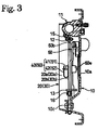
- the structure and action of this type of drum brake device is disclosed well in JP09273573. Therefore, an explanation here will be limited to a general description as to an overall structure and braking action of the drum brake device with reference to Figures 1-3 of this invention employing the same basic structure as in JP09273573.Terms such as “upper” and “lower” or “left” and “right” used herein are explained with reference to Figure 1.
- a back plate 10 is a disc-shape as a whole.
- a pair of brake shoes 20, 30 comprise almost arc-shaped shoe rims 20a, 30a, shoe webs 20b, 30b fixed on inner circumferential surfaces of the shoe rims 20a, 30a designed to make T-shapes when viewed cross-sectionally, and linings 20c, 30c affixed on outer circumferential surfaces of the shoe rims 20a, 30a.
- One side surface of the shoe rims 20a, 30a is movably put on the back plate 10.
- a wheel cylinder 11 of a hydraulic type actuator positioned between upper adjacent ends of the brake shoes 20b, 30b is fixed on the back plate 10 by bolts, and a pair of pistons 11a (one in the right side only in Figure 1) make slight contact with the upper end surfaces of the shoe webs 20b, 30b.
- Lower ends of the shoe webs 20b, 30b are supported by an anchor 10c fixed on the back plate 10 by a fixing means, such as rivets.
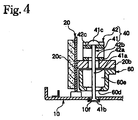
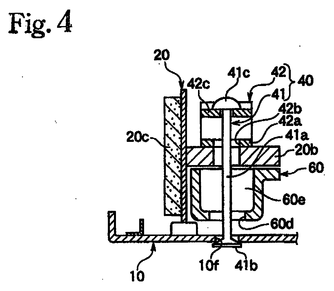
- a pair of shoe-hold mechanisms 40, 50 comprises shoe-hold pins 41, 51 and shoe-hold springs 42, 52 (see Figure 4).
- Top ends of the shoe-hold pins 41, 51 swingably engage the back plate 10 and retain the shoe-hold springs 42, 52, positioned on shoe webs 20b, 30b so as to contract the same to form almost a U-shape, thereby urging the brake shoes 20, 30 toward the back plate 10.
- surfaces of the linings 20c, 30c are constantly parallelized, within a certain clearance, to an inner circumferential surface of a brake drum (not shown in the figures). Details of the shoe-hold mechanism 40 at the left side of the figures will be explained later.
- a first strut 12 adjacent to the wheel cylinder 11 has a screw mechanism and is extended between both shoe webs 20b, 30b.
- Extending or shortening the first strut 12 adjusts the clearance between the linings 20c, 30c and the brake drum (not shown in the figures).
- a pair of upper and lower shoe-return springs 15, 16 urging the pair of brake shoes 20, 30 to approach each other are stretched between both shoe webs 20b, 30b. This prevents dragging of the linings 20c, 30c when releasing the brake.
- the structure of the mechanical type brake mechanism will be explained next.
- a free end 60b of the brake lever 60 is connected to a cable end 62a of a brake cable 62 functioning as a remote force transmitting member, and a projection 60c formed on an outer circumferential edge of the brake lever 60 near the free end 60b, just like shown in Figure 1, abuts against an inner circumferential surface of the shoe rim 20a, thereby restricting a returning position of the brake lever 60.
- a cable guide 10d is fixed on the back plate 10 to smoothly guide the brake cable 62, and a guide pipe 10e fixes one end of an outer casing.
- the outer casing is a member to protect the brake cable 62 that may be directly exposed to outside air.
- a second strut 13 is extended between a lower end of the pivot lever 14 and the lower portion of the brake lever 60, and the upper end of the pivot lever 14 engages with a right end portion of the strut 12.
- One end of which has a head 41b wherein the head declines or slopes to meet the stem of the shoe-hold pin in order to allow the pin to swingably move, the other end of which has an enlarged head 41c in order to fix the shoe-hold spring 42.
- the head 41b at one end of the shoe-hold pin 41 swingably engages with an engagement hole 10f formed in the back plate 10, and the head 41c at the other end of the shoe-hold pin 41 penetrates through a by-pass hole 20d formed in the shoe web 20b and a by-pass hole 42b formed in the bottom branch 42a of the shoe-hold spring 42, wherein a top branch 42c of the shoe-hold spring 42 facing the bottom branch 42a of the shoe-hold spring 42 is fixed by the shoe-hold pin 41.
- the brake shoe 20 is resiliently supported on the back plate 10.
- the brake lever 60 is positioned such that its outer circumferential edge is adjacent to the stem 41a of the shoe-hold pin 41.
- the automatic stroke adjustment mechanism is configured in the second strut 13, and an explanation as to its structure and action is disclosed in Publication Number JP10110758 which is hereby incorporated by reference. Braking action of the brake device with the above-structure will be explained with reference to Figure 1.
- a mechanical type actuator action will be explained next. If the free end 60b of the brake lever 60 is pulled via a brake cable 62, the brake lever 60 rotates clockwise with the pin 61 as a pivot point, and the operation force is transmitted to the second strut 13, the pivot lever 14, and the first strut 12 respectively so as to move the left brake shoe 20 outward to cause a frictional engagement with the brake drum.
- the right brake shoe 30 moves outward via the protuberance 14a of the pivot lever 14 to cause a frictional engagement with the brake drum.
- this drum brake device is defined to be a dual mode type drum brake device.
- a conventional drum brake device has the following drawbacks: Recently, for safety reasons, the number of vehicles utilizing anti-lock brake control devices, has been increasing.
- a sensor wheel rotating together with the brake drum is positioned at the central region of the brake, and a sensor faces an outer circumferential surface of the sensor wheel with a certain clearance.
- a body of the sensor penetrates through a through hole 10g (see Figure 1) formed in the back plate 10 to be installed. Accordingly, unless a sufficiently effective brake lever stroke is reserved, the sensor may be damaged.
- the shoe-hole pin 61 rises from the back plate and passes or penetrates through the by-pass hole.
- the flat brake lever plate is positioned beneath the shoe web and parallel to the back plate with a certain clearance, and the outer circumferential edge of the brake lever approaches the inner circumferential surface of the shoe rim.
- the shoe-hold pin has a semi-sphere head at one end of which is swingably engaged with a back plate. Therefore, there is no guarantee of maintaining a stable condition.
- the shoe-hold pin leans towards the outside of the brake because of the sloped surface of the head.
- the by-pass hole of the brake lever must be designed to be of sufficient size. As such, an inner circumferential line of the brake lever at the brake center side is necessarily projected resulting in diminishing the space at the central region of the brake.
- a large by-pass hole needs to be formed in the flat brake lever, which reduces the strength of the brake lever. Because of this larger hole, a section of the brake lever surrounding the by-pass hole needs to be wider, which also contributes to the diminished space at the central region of the brake.
- a reinforcement plate may be added to increase the strength of the brake lever, but adding an additional member automatically increases the total weigh and makes the assembly more complex.
- This invention is a drum brake device comprising a brake shoe being movably parallel to a surface on a fixed back plate, a brake lever positioned beneath a shoe web of the brake shoe, a base end of which pivotally supported at one end of the shoe web, a shoe-hold pin, one end of which swingably engages with the back plate while the other end freely penetrates a by-pass hole formed in the brake lever.
- a shoe-hold spring is retained by the other end of the shoe-hold pin so as to urge the brake shoe toward the back plate.
- the brake shoe frictionally engages with the brake drum upon pulling a free end of the brake lever by a remote force transmitting member, and a part of the brake lever surrounding the by-pass hole is positioned closer to and is facing the back plate.
- This invention also is the drum brake device as above, wherein a part of the brake lever, surrounding the by-pass hole, is drawn to form a hollow cavity or is bent or shaped to form a groove.
- Example 1 of this invention will be explained with reference to Figure 4 in addition to Figures 1 and 3.
- a by-pass hole 60d is formed in the mid-portion of the brake lever 60 and a stem 41a of a shoe-hold pin 41 penetrates through the by-pass hole 60d, and a part surrounding the by-pass hole 60d is drawn by press to be shaped into a hollow cavity 60e, and a bottom portion of the cavity 60e is positioned closer to and is facing towards the back plate 10.
- a shoe-hold pin 41 is installed at an inclined angle, or if an angle of the shoe- hold pin 41 becomes larger due to lining wear 20c, the amount of variation in the clearance between the shoe-hold pin 41 and an inner surface of the by-pass hole 60d of the brake lever 60 is quite small.
- Example 2 will be explained with reference to Figure 5.
- Example 2 is almost identical to the brake lever 60 of Example 1 except for the shape of its by-pass hole 60d. Therefore, the rest of the explanation is omitted.
- the section around by-pass hole 60d is designed to be bent in a shape in accordance with a groove 60f so as to approach and face the back plate 10, and a rib 60g with a predetermined width and height along a plate surface of the groove 60f is integrally formed therewith.
- the rib 60g is not a prerequisite of this invention and is provided as necessary.
- the groove 60f is proven to provide about the same advantages as the pocket 60e, and an explanation of which will be omitted.
- the above examples are described in relation to an application in a dual mode type drum brake device; however, applications of this invention is not limited to the dual mode type but for example a publicly known leading trailing type drum brake, duo servo type drum brake device or a drum brake device with a single shoe as shown in Publication Number JP09324829.
- the drum brake device of this invention has the following advantages.
- the shoe-hold pin rises from the back plate and freely penetrates through the by-pass hole.
- the by-pass hole is formed in the brake lever plate that is positioned beneath the shoe web and parallel to the back plate and the outer circumferential edge of the brake lever may be designed to approach the inner circumferential surface of the shoe rim.
- the part of the brake lever around the by-pass hole is positioned closer to and is facing the back plate, when the shoe-hold pin is installed at an incline at an engagement point with the back plate as the pivot point or when an angle of the shoe-hold pin becomes larger due to the lining wear, the amount of variation in the clearance between the shoe-hold pin 41 and an inner surface of the by-pass hole of the brake lever is quite small.
- the size of the by-pass hole may be designed without considering the amount of variation, and the width of the brake lever around this area may be narrower, thereby securing a larger space at the central region of the brake. Therefore, the large effective stroke of the brake lever is realized, which may prevent damage to the anti-lock sensor and may not interfere with the brake drum hub.
- the part of the brake lever around the by-pass hole may be integrally formed in a hollow drawn by press or integrally formed in a groove with a rib. Therefore, the rigidity is maintained even if the width of the brake lever around the by-pass hole may be a bit narrower, and the assembling process is made easier.
- This invention can be applied to various types of drum brakes employing a dual mode type, leading trailing type, duo servo type, and a type of a drum brake with single brake shoe and provides a wide range of applicability.
Landscapes
- Engineering & Computer Science (AREA)
- General Engineering & Computer Science (AREA)
- Mechanical Engineering (AREA)
- Braking Arrangements (AREA)
Abstract
Description
Claims (3)
- A drum brake device comprising a brake shoe being movably parallel to a surface on a fixed back plate, a brake lever superposed on a shoe web of the brake shoe, positioned between the back plate and the shoe web, but adjacent to the shoe web, a base end of which is pivotally supported at one end of the shoe web, a shoe-hold pin, one end of which swingably engages with the back plate while the other end of which freely penetrates a by-pass hole passing through the brake lever, and a shoe-hold spring retained by the other end of the shoe-hold pin so as to urge the brake shoe toward the back plate, which is characterized in that the brake shoe frictionally engages with the brake drum upon pulling a free end of the brake lever by a remote force transmitting member, and wherein a part of the brake lever surrounding the by-pass hole is positioned closer to and is facing the back plate.
- The drum brake device as claimed in Claim 1, which is characterized in that a part of the brake lever, surrounding the by-pass hole, is drawn to form a hollow cavity.
- The drum brake device as claimed in Claim 1, which is characterized in that a part of the brake lever, surrounding the by-pass hole, is bent to form a groove.
Applications Claiming Priority (2)
| Application Number | Priority Date | Filing Date | Title |
|---|---|---|---|
| JP2000390390A JP2002188665A (en) | 2000-12-22 | 2000-12-22 | Drum brake device |
| JP2000390390 | 2000-12-22 |
Publications (2)
| Publication Number | Publication Date |
|---|---|
| EP1217245A2 true EP1217245A2 (en) | 2002-06-26 |
| EP1217245A3 EP1217245A3 (en) | 2003-11-26 |
Family
ID=18856768
Family Applications (1)
| Application Number | Title | Priority Date | Filing Date |
|---|---|---|---|
| EP01403360A Withdrawn EP1217245A3 (en) | 2000-12-22 | 2001-12-24 | Parking brake actuating lever structure for drum brake device |
Country Status (4)
| Country | Link |
|---|---|
| US (1) | US6554110B2 (en) |
| EP (1) | EP1217245A3 (en) |
| JP (1) | JP2002188665A (en) |
| KR (1) | KR20020051890A (en) |
Families Citing this family (3)
| Publication number | Priority date | Publication date | Assignee | Title |
|---|---|---|---|---|
| JP3933487B2 (en) * | 2002-02-14 | 2007-06-20 | 日清紡績株式会社 | Dual mode drum brake device |
| FR2839537B1 (en) * | 2002-05-07 | 2004-07-09 | Bosch Gmbh Robert | VEHICLE DRUM BRAKE AND ASSEMBLY METHOD THEREOF |
| KR20240012825A (en) * | 2022-07-21 | 2024-01-30 | 에이치엘만도 주식회사 | Drumbrake |
Family Cites Families (7)
| Publication number | Priority date | Publication date | Assignee | Title |
|---|---|---|---|---|
| JPS5852342U (en) * | 1981-10-06 | 1983-04-09 | トヨタ自動車株式会社 | Internally expandable drum brake |
| US5070968A (en) * | 1989-09-18 | 1991-12-10 | Kelsey-Hayes Company | Leading/trailing drum brake having servo parking brake |
| US5275260A (en) * | 1989-09-18 | 1994-01-04 | Kelsey-Hayes Company | Dual mode drum brake assembly |
| JP3245768B2 (en) * | 1996-04-03 | 2002-01-15 | 日清紡績株式会社 | Drum brake device |
| JP3341143B2 (en) * | 1996-04-04 | 2002-11-05 | 日清紡績株式会社 | Drum brake device |
| JPH10299801A (en) * | 1997-04-22 | 1998-11-13 | Nisshinbo Ind Inc | Drum brake device |
| JP3341150B2 (en) * | 1998-04-22 | 2002-11-05 | 日清紡績株式会社 | Drum brake device |
-
2000
- 2000-12-22 JP JP2000390390A patent/JP2002188665A/en not_active Withdrawn
-
2001
- 2001-12-22 KR KR1020010083227A patent/KR20020051890A/en not_active Withdrawn
- 2001-12-24 EP EP01403360A patent/EP1217245A3/en not_active Withdrawn
- 2001-12-26 US US10/025,997 patent/US6554110B2/en not_active Expired - Fee Related
Also Published As
| Publication number | Publication date |
|---|---|
| US6554110B2 (en) | 2003-04-29 |
| JP2002188665A (en) | 2002-07-05 |
| EP1217245A3 (en) | 2003-11-26 |
| US20020092714A1 (en) | 2002-07-18 |
| KR20020051890A (en) | 2002-06-29 |
Similar Documents
| Publication | Publication Date | Title |
|---|---|---|
| US7086506B2 (en) | Pad retraction spring for a brake shoe assembly and a disc brake assembly | |
| US5921354A (en) | Self-energizing anti-creep parking and emergency brake mechanism for disc brake assembly | |
| US5630486A (en) | Mechanical actuation device for drum brake | |
| KR19980032597A (en) | Drum brake device | |
| US3351159A (en) | Backing plate, anchor construction | |
| US6394237B1 (en) | Automatic shoe clearance adjustment device for a drum brake | |
| US6554110B2 (en) | Drum brake device | |
| US6065571A (en) | Drum brake system and device | |
| JPH0327775B2 (en) | ||
| EP1217244B1 (en) | Drum brake device with parking brake actuator, | |
| US6345708B1 (en) | Brake shoe anchor device for an internal drum brake device | |
| EP0896167B1 (en) | Drum Brake Device | |
| EP1217243A2 (en) | Drum brake device with parking brake actuator | |
| US6390248B1 (en) | Dual mode drum brake device | |
| US7490702B1 (en) | Parking and emergency brake actuator for a drum-in-hat disc brake assembly | |
| US6681902B1 (en) | Brake shoe mounting system for a vehicle brake assembly | |
| US4595082A (en) | Drum brake | |
| EP0049583B1 (en) | Automatic wear adjuster for drum brakes | |
| EP1869337B1 (en) | Drum brake | |
| KR200276253Y1 (en) | Drum brake | |
| JPS6112420Y2 (en) | ||
| JPS6118259Y2 (en) | ||
| KR100978753B1 (en) | Drum brake | |
| KR100217674B1 (en) | Brake shoe | |
| JPH11280802A (en) | Brake shoe holding mechanism for drum brake |
Legal Events
| Date | Code | Title | Description |
|---|---|---|---|
| PUAI | Public reference made under article 153(3) epc to a published international application that has entered the european phase |
Free format text: ORIGINAL CODE: 0009012 |
|
| AK | Designated contracting states |
Kind code of ref document: A2 Designated state(s): AT BE CH CY DE DK ES FI FR GB GR IE IT LI LU MC NL PT SE TR |
|
| AX | Request for extension of the european patent |
Free format text: AL;LT;LV;MK;RO;SI |
|
| PUAL | Search report despatched |
Free format text: ORIGINAL CODE: 0009013 |
|
| AK | Designated contracting states |
Kind code of ref document: A3 Designated state(s): AT BE CH CY DE DK ES FI FR GB GR IE IT LI LU MC NL PT SE TR |
|
| AX | Request for extension of the european patent |
Extension state: AL LT LV MK RO SI |
|
| AKX | Designation fees paid | ||
| REG | Reference to a national code |
Ref country code: DE Ref legal event code: 8566 |
|
| STAA | Information on the status of an ep patent application or granted ep patent |
Free format text: STATUS: THE APPLICATION IS DEEMED TO BE WITHDRAWN |
|
| 18D | Application deemed to be withdrawn |
Effective date: 20040527 |