EP1217213A2 - Scroll-type compressor - Google Patents
Scroll-type compressor Download PDFInfo
- Publication number
- EP1217213A2 EP1217213A2 EP01130202A EP01130202A EP1217213A2 EP 1217213 A2 EP1217213 A2 EP 1217213A2 EP 01130202 A EP01130202 A EP 01130202A EP 01130202 A EP01130202 A EP 01130202A EP 1217213 A2 EP1217213 A2 EP 1217213A2
- Authority
- EP
- European Patent Office
- Prior art keywords
- scroll member
- guide hole
- movable scroll
- plunger
- shaft
- Prior art date
- Legal status (The legal status is an assumption and is not a legal conclusion. Google has not performed a legal analysis and makes no representation as to the accuracy of the status listed.)
- Granted
Links
- 230000007246 mechanism Effects 0.000 claims abstract description 34
- 230000008859 change Effects 0.000 claims abstract description 3
- 230000006835 compression Effects 0.000 claims description 27
- 238000007906 compression Methods 0.000 claims description 27
- 238000004891 communication Methods 0.000 claims description 2
- 239000003507 refrigerant Substances 0.000 description 18
- 230000002093 peripheral effect Effects 0.000 description 9
- 230000000875 corresponding effect Effects 0.000 description 7
- 238000000034 method Methods 0.000 description 6
- 230000008569 process Effects 0.000 description 6
- 238000004378 air conditioning Methods 0.000 description 4
- 238000013459 approach Methods 0.000 description 3
- 230000007423 decrease Effects 0.000 description 3
- 238000005057 refrigeration Methods 0.000 description 3
- 238000006243 chemical reaction Methods 0.000 description 2
- 238000010586 diagram Methods 0.000 description 2
- 238000006073 displacement reaction Methods 0.000 description 2
- 230000000694 effects Effects 0.000 description 2
- 238000003825 pressing Methods 0.000 description 2
- 230000001276 controlling effect Effects 0.000 description 1
- 230000002596 correlated effect Effects 0.000 description 1
- 230000008878 coupling Effects 0.000 description 1
- 238000010168 coupling process Methods 0.000 description 1
- 238000005859 coupling reaction Methods 0.000 description 1
- 239000012530 fluid Substances 0.000 description 1
- 239000000446 fuel Substances 0.000 description 1
- 230000004048 modification Effects 0.000 description 1
- 238000012986 modification Methods 0.000 description 1
- 231100000989 no adverse effect Toxicity 0.000 description 1
- 230000001681 protective effect Effects 0.000 description 1
- 230000009467 reduction Effects 0.000 description 1
- 238000005096 rolling process Methods 0.000 description 1
- 239000007787 solid Substances 0.000 description 1
- 238000012546 transfer Methods 0.000 description 1
- 230000007704 transition Effects 0.000 description 1
- 238000011144 upstream manufacturing Methods 0.000 description 1
Images






Classifications
-
- F—MECHANICAL ENGINEERING; LIGHTING; HEATING; WEAPONS; BLASTING
- F04—POSITIVE - DISPLACEMENT MACHINES FOR LIQUIDS; PUMPS FOR LIQUIDS OR ELASTIC FLUIDS
- F04C—ROTARY-PISTON, OR OSCILLATING-PISTON, POSITIVE-DISPLACEMENT MACHINES FOR LIQUIDS; ROTARY-PISTON, OR OSCILLATING-PISTON, POSITIVE-DISPLACEMENT PUMPS
- F04C28/00—Control of, monitoring of, or safety arrangements for, pumps or pumping installations specially adapted for elastic fluids
- F04C28/18—Control of, monitoring of, or safety arrangements for, pumps or pumping installations specially adapted for elastic fluids characterised by varying the volume of the working chamber
- F04C28/22—Control of, monitoring of, or safety arrangements for, pumps or pumping installations specially adapted for elastic fluids characterised by varying the volume of the working chamber by changing the eccentricity between cooperating members
-
- F—MECHANICAL ENGINEERING; LIGHTING; HEATING; WEAPONS; BLASTING
- F04—POSITIVE - DISPLACEMENT MACHINES FOR LIQUIDS; PUMPS FOR LIQUIDS OR ELASTIC FLUIDS
- F04C—ROTARY-PISTON, OR OSCILLATING-PISTON, POSITIVE-DISPLACEMENT MACHINES FOR LIQUIDS; ROTARY-PISTON, OR OSCILLATING-PISTON, POSITIVE-DISPLACEMENT PUMPS
- F04C18/00—Rotary-piston pumps specially adapted for elastic fluids
- F04C18/02—Rotary-piston pumps specially adapted for elastic fluids of arcuate-engagement type, i.e. with circular translatory movement of co-operating members, each member having the same number of teeth or tooth-equivalents
- F04C18/0207—Rotary-piston pumps specially adapted for elastic fluids of arcuate-engagement type, i.e. with circular translatory movement of co-operating members, each member having the same number of teeth or tooth-equivalents both members having co-operating elements in spiral form
- F04C18/0215—Rotary-piston pumps specially adapted for elastic fluids of arcuate-engagement type, i.e. with circular translatory movement of co-operating members, each member having the same number of teeth or tooth-equivalents both members having co-operating elements in spiral form where only one member is moving
Definitions
- the present invention relates to a displacement compressor used for compressing the refrigerant of an automotive air-conditioning system, or in particular to a scroll-type compressor.
- the scroll-type compressor can operate with 0 % capacity to reduce the discharge capacity thereof to zero in substantially the same manner as if the electromagnetic clutch is off on the one hand and that the power loss in operation is so small as to have no adverse effect on the fuel cost of the automotive vehicle on the other.
- variable-capacity type refrigerant compressor of a scroll type described in Japanese Unexamined Patent Publication No. 5-231353 has been proposed in the prior art.
- a bypass is arranged between a compression chamber formed between a stationary scroll member and a movable scroll member and an intake chamber on the low-pressure side, and the discharge capacity is changed by opening/closing the bypass with a shuttle valve or the like. Since the compressed refrigerant cannot be fully returned to the intake chamber when the compressor is operating at high speed, however, it is difficult to achieve 0 % capacity.
- the object of the present invention is to obviate the aforementioned problem of the prior art, using a novel means, and to provide a compact, lightweight and inexpensive scroll-type compressor in which not only the electromagnetic clutch is eliminated but also the power loss is minimized in the 0 % capacity operation by realizing a 0 % capacity operation.
- a scroll-type compressor comprises a compliance crankshaft mechanism interposed between a shaft and a movable scroll member for allowing the orbiting radius of the movable scroll member to be reduced steplessly substantially to zero, wherein one of the movable scroll member and the housing is formed with a guide hole having an inclined surface with the depth thereof along the center axis of the shaft changing radially, and the other one of the movable scroll member and the housing not formed with the guide hole supports a plunger adapted to move toward and away from the guide hole to select a position to engage or not to engage the guide hole.
- the plunger is controlled by control means to advance and retract along the center axis of the shaft.
- a guide hole can alternatively be formed in the end plate of the movable scroll member, and the plunger is supported by the housing.
- a guide hole may be formed in the plunger adapted to move by being supported on the housing, and a pin engaging the guide hole may be arranged on the end plate of the movable scroll member as another alternative.
- a guide hole is formed in the eccentric bushing of the compliance crankshaft mechanism supporting the end plate of the movable scroll member, while at the same time supporting the plunger on the shaft journaled by the housing.
- a guide hole configured of a two-stepped conical surface can be reduced in depth.
- the guide hole is formed of a curved surface such as a quadratic surface of revolution
- the same effect can be achieved smoothly as the two-stepped conical surface.
- Provision of energization means such as a spring for retreating the plunger completely from the position of engagement with the guide hole can always realize the operation of 100 % capacity. Nevertheless, the configuration can be simplified by omitting the energization means.
- the edge portion of the guide hole opening is formed with a cylindrical surface, on the other hand, the rotation of the movable scroll member can be prevented by use of the guide hole, and therefore the need of an antirotation mechanism is eliminated.
- One or several plungers may be provided.
- a single annular plunger is arranged in such a position as to surround the centerline of the shaft, the axial force can be generated against the guide hole uniformly around the shaft.
- the movable scroll member can be smoothly operated in radial direction, thereby making it possible to prevent vibration or the like.
- a counter weight is mounted radially movably on the shaft with a bifacial portion, while the movable scroll member is moved radially in such a manner as to reduce the discharge capacity to zero, the counter weight that has thus far been in contact with the outer periphery of an eccentric bushing constituting a part of the compliance crankshaft mechanism comes into contact with the outer periphery of a large-diameter boss portion constituting a part of the shaft while leaving the outer periphery of the eccentric bushing from a predetermined time point.
- the compression chamber of intermediate pressure communicates with the low-pressure side when the bypass is opened by the control means.
- the discharge capacity is reduced, so that an intermediate discharge capacity between 100 % and 0 % can be achieved in stable fashion. In this way, the discharge capacity can be selectively controlled in three stages very easily.
- the operation of 0 % capacity with a very small power loss can be realized by reducing the orbiting radius of the movable scroll member to zero. Therefore, a scroll-type compressor with a variable discharge capacity free of the electromagnetic clutch can be provided.
- Figs. 1 and 2 show a general configuration of a scroll-type compressor C1 according to a first embodiment of the invention.
- Fig. 1 shows the compressor operating at 100 % capacity
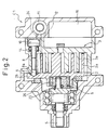
- Fig. 2 shows the compressor operating at 0 % capacity.
- reference numeral 1 designates a front housing
- numeral 2 a movable scroll member orbitably supported in the housing
- numeral 3 a stationary scroll member constituting a part of the housing
- numeral 4 a rear housing.
- the front housing 1, the stationary scroll member 2 and the rear housing 4 are integrated by coupling means such as a through bolt, not shown, and constitute a single housing.
- Numeral 5 designates a drive shaft rotatably supported in the front housing 1. A part of the shaft 5 is formed integrally with a counter weight 5a for suppressing the unbalanced vibrations caused by the orbital motion of the movable scroll member 2.
- Numeral 6 designates what is called a compliance crankshaft mechanism, which supports the movable scroll member 2 orbitably while allowing the amount of eccentricity of the center of the movable scroll member 2 with respect to the shaft 5, i.e. the orbiting radius of the movable scroll member 2 to change continuously.
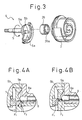
- An example of the structure of this compliance crankshaft mechanism is shown in the perspective view of Fig. 3 as well as Figs. 1 and 2.
- the boss portion 5c of the shaft 5 where the counter weight 5a is mounted is formed integrally with an eccentric pin 5b extending along the axis in a position eccentric with respect to the shaft 5, which eccentric pin 5b is rotatably inserted into the eccentric hole 26a formed eccentrically in the cylindrical eccentric bushing 26.
- the eccentric bushing 26 rotatably supports, through a needle bearing 20, the cylindrical boss portion 2c arranged on the back of the center of the end plate 2b of the movable scroll member 2.
- a return spring 23 constituted of a coil spring or a spiral spring is mounted, and the ends of the return spring 23 are mounted on the boss portion 5c and the eccentric bushing 26.
- the boss portion 5c having the eccentric pin 5b of the compliance crankshaft mechanism 6 and the eccentric bushing 26 make up a double eccentric mechanism.
- the return spring 23 constantly energizes the movable scroll member 2 radially outward in such a manner as to increase the orbiting radius and the amount of eccentricity of the movable scroll member 2 with respect to the shaft 5.
- the energizing force of the return spring 23 rotates the eccentric bushing 26 on the eccentric pin 5b of the shaft 5, so that the discharge capacity of the scroll-type compressor C1 restores to 100 % from 0 %.
- the shaft 5 is rotated by the applied driving torque.
- the compliance crankshaft mechanism 6 forces the movable scroll member 2 to orbit.
- the driving torque is transmitted through the eccentric bushing 26 and the eccentric pin 5b of the compliance crankshaft mechanism 6 making up the double eccentric mechanism, and the eccentric pin 5b and the eccentric bushing 26 are relatively rotated in accordance with the magnitude of the transmitted torque.
- the amount of eccentricity and the orbiting radius of the movable scroll member 2 are increased, thereby generating pressure of a magnitude suitable for pressing the spiral blade 2a of the movable scroll member 2 against the spiral blade 3a of the stationary scroll member 3.
- this operation is somewhat enhanced by the return spring 23.
- the component part 7 of which only the contour is shown in Figs. 1 and 2 is an antirotation mechanism always arranged normally in the scroll-type compressor and connects the end plate 2b of the movable scroll member 2 and the front housing 1 to each other in such a manner as to allow the movable scroll member 2 only to orbit while preventing the rotation thereof without regard to the orbiting radius or the magnitude of the movable scroll member 2.
- the greatest feature of the scroll-type compressor C1 according to the first embodiment lies in that a part of the outer shell of the stationary scroll member 3 constituting a part of the housing is formed with a small cylinder 3b along the axis into which the plunger 8 is slidably inserted.
- the hemispherical head portion 8a of the plunger 8 is projected from the cylinder 3b and is in engaging contact with the inner surface of the guide hole 9 having two-stepped conical surface formed on the end plate 2b of the movable scroll member 2.
- the annular conical surface at the inlet around the guide hole 9 having a comparatively small sectional inclination angle with respect to the axis of the shaft 5 is designated as 9a
- the conical surface having a comparatively large inclination angle on the bottom portion of the guide hole 9 is designated as 9b.
- Numeral 10 designates a control pressure chamber formed as a space on the back of the disk portion 8b formed at the rear end portion of the plunger 8.
- Numeral 11 designates a control valve for generating a control pressure to be imparted to the control pressure chamber 10.
- Numeral 12 designates a discharge pressure path for introducing the discharge pressure (high-pressure) to the control valve 11, numeral 13 an intake pressure path for introducing the intake pressure (low-pressure) similarly, and numeral 24 a control pressure path for introducing the control pressure from the control valve 11 to the control pressure chamber 10.
- Numeral 14 designates a spring for urging the plunger 8 rightward in Fig. 1 to keep the head portion 8a of the plunger 8 and the guide hole 9 away from each other during the 100 % capacity operation.
- numeral 15 designates a pair of compression chambers formed between the spiral blade 2a of the movable scroll member 2 and the spiral blade 3a of the stationary scroll member 3 on the two radial sides with respect to the central portion, at which a single unified compression chamber 15a is formed of the particular pair of the compression chambers 15.
- a discharge valve 17, as a check valve, is arranged between the compression chamber 15a at the central portion and the discharge chamber 16 formed as a space from the back of the end plate 3c of the stationary scroll member 3 to the interior of the rear housing 4.
- Numeral 18 designates a valve stop plate for preventing the discharge valve 17 from being excessively opened.
- Numeral 19 designates a bearing arranged on the front housing 1 for journaling the shaft 5, and numeral 21 tip seals arranged along the forward end surface of the movable and stationary spiral blades 2a, 3a for preventing the pressured refrigerant from leaking out of the compression chamber 15 toward the low-pressure side.
- Numeral 22 designates a shaft seal arranged to prevent the refrigerant from leaking outside from around the shaft 5.
- the scroll-type compressor C1 has the structure described above and operates in the following way.
- the plunger 8 is pushed rearward by the spring 14 so that the head portion 8a of the plunger 8 is retreated to the position where it is out of engagement with the guide hole 9.
- the head portion 8a has no operating effect on the movable scroll member 2. Therefore, the movable scroll member 2 assumes a maximum amount of eccentricity and, as in the normal scroll-type compressor, orbits with the maximum orbiting radius to produce the 100 % discharge capacity.
- the spiral blade 2a of the movable scroll member 2 is pressed against the spiral blade 3a of the stationary scroll member 3 radially outward by the resultant force of the radial pressure F R generated by the relative rotation (including the relative rotation by the urging force of the return spring 23) of the eccentric bushing 26 around the eccentric pin 5b when the compliance crankshaft mechanism 6 transmits the driving torque on the one hand and the centrifugal force F C generated by the orbiting of the movable scroll member 2 on the other hand.
- the compression chamber 15 is closed.
- the refrigerant introduced into the pair of compression chambers 15 from the intake chamber 25 on the outer peripheral portion is compressed and the pressure increases.
- the refrigerant thus merges into the single compression chamber 15a formed at the central portion and, opening the discharge valve 17 under pressure, is discharged into the discharge chamber 16.
- the compression reactive force F G is exerted on the movable scroll member 2 as a reaction of compression of the refrigerant in the compression chamber 15.
- the magnitude of the compression reactive force F G and the magnitude of the pressure F R generated by the compliance crankshaft mechanism 6 are correlated to each other.
- the force for pressing the spiral blade 2a of the movable scroll member 2 radially against the spiral blade 3a of the stationary scroll member 3 is primarily the resultant force of the radial pressure F R generated in the compliance crankshaft mechanism 6 and the centrifugal force F C generated by the orbiting of the movable scroll member 2.
- This resultant force is indicated by the solid arrow in Fig. 6.
- Fig. 6 shows the operation at 100 % capacity.
- the radial force F 2 as shown in Fig. 4A generated by the contact portion between the plunger 8 and the guide hole 9 is not yet generated.
- the plunger 8 is activated to reduce the discharge capacity of the compressor C1 from 100 % capacity, however, the radial force F 2 as indicated by the dashed arrow in Fig.
- character C designates the center of the stationary scroll member 3
- character M the center of the movable scroll member 2.
- the amount of eccentricity represented by the distance between the centers C and M constitutes the orbiting radius R.
- the refrigerant at a high discharge pressure, is introduced from the discharge chamber 16 to the control pressure chamber 10 by the switching operation of the control valve 11.
- the plunger 8 As the disk portion 8b receives the discharge pressure, the plunger 8 is pushed toward the front against the force of the spring 14, and as shown in Fig. 2, the head portion 8a of the plunger 8 advances into the guide hole 9.
- the head portion 8a of the plunger 8 comes into contact with the conical surface 9a having a small inclination angle formed around the guide hole 9.
- the axial force F 1 determined by the magnitude of the discharge pressure and the pressure-receiving area of the disk portion 8b of the plunger 8 is converted into the vertical (radial) force F 2 for pushing the movable scroll member 2 in the direction perpendicular to the axis of the shaft 5, i.e. the force for reducing the discharge capacity toward 0 % at the contact point between the head portion 8a of the plunger 8 and the conical surface 9a of the guide hole 9. Since the inclination angle of the conical surface 9a is comparatively small, the force F 2 is amplified considerably with respect to the force F 1 .
- the smaller amount of eccentricity reduces the centrifugal force exerted on the movable scroll member 2.
- the movable scroll member 2 can be moved in such a direction as to further reduce the amount of eccentricity and the orbiting radius.
- the movable scroll member 2 moves radially to the position where the center M thereof coincides with the center C of the stationary scroll member 3 and the shaft 5, thereby reducing the amount of eccentricity and the orbiting radius of the movable scroll member 2 to zero.
- Fig. 7 is a sectional view showing the positions of the spiral blade 2a of the movable scroll member 2 and the spiral blade 3a of the stationary scroll member 3, and the relative positions of the plunger 8 and the guide hole 9 under this operation condition. Under this condition, the movable scroll member 2 neither rotates nor orbits but is substantially stationary.
- the force F 3 generated when transferring from the 100 % capacity operation shown in Fig. 1 to the 0 % capacity operation shown in Fig. 2 is indicated by an arrow, for the convenience sake, in Fig. 5.
- the force F 3 overcomes the resultant force of the pressure F R and the centrifugal force FC, so that the amount of eccentricity and the orbiting radius R of the movable scroll member 2 are reduced to zero.
- the hemispherical head portion 8a of the plunger 8 advances into the guide hole 9
- the orbiting radius R and the amount of eccentricity of the movable scroll member 2 are progressively reduced.
- the movable scroll member 2 ceases to orbit, so that the centrifugal force F C due to the orbiting is reduced and finally becomes zero.
- the compression chamber 15 formed between the spiral blades 2a and 3a opens and ceases to be closed, and therefore the refrigerant is not compressed.
- the drive torque approaches zero, and so does the radial pressure F R generated in the compliance crankshaft mechanism 6. This is also the case with the compression reaction FG.
- the resultant force of the centrifugal force F C and the pressure F R assumes a value approximate to zero.
- the force F 3 generated in the contact portion between the plunger 8 and the guide hole 9 against the resultant force increases beyond the particular resultant force.
- the center M of the movable scroll member 2 comes to coincide with the center C of the stationary scroll member 3, so that the amount of eccentricity and the orbiting radius R of the movable scroll member 2 become zero and the compressor C1 enters the 0 % capacity operation.
- the radial force F 3 is not so large. As long as the compressor C1 is in 0 % capacity operation, however, the radial force F 3 is not reduced to zero as it works against the urging force of the return spring 23.
- the force F 2 increases for moving the movable scroll member 2 in such a radial direction as to reduce the amount of eccentricity and the orbiting radius.
- the scroll-type compressor C1 according to the first embodiment is used as a refrigerant compressor for the refrigeration cycle of the air-conditioning system
- the plunger 8 advances deep into the guide hole 9 so that the amount of eccentricity and the orbiting radius R of the movable scroll member 2 become zero, and the discharge capacity of the compressor C1 decreases from 100 % to 0 %, even when the high-pressure upstream of the expansion valve in the refrigeration cycle gradually decreases to uniform pressure
- the compressor C1 continues operating at the discharge capacity of 0 % as long as the axial force F 1 generated by the pressure of the control pressure chamber 10 received by the disk portion 8b of the plunger 8 remains larger than the resultant force of the force of the spring 14 and the return spring 23.
- the amount of eccentricity and the orbiting radius R of the movable scroll member 2 can be easily and smoothly reduced to zero by adding a simple mechanism including the plunger 8 to the conventional scroll-type compressor.
- the needle bearing 20, the bearing 19 and the shaft seal 22 constitute the only sliding or rolling portions, thereby realizing the 0 % capacity operation with a very small power loss.
- Fig. 9 shows a structure of the scroll-type compressor C2 according to a second embodiment of the invention.
- This scroll-type compressor C2 is different from the scroll-type compressor C1 according to the first embodiment in that the relative positions of the plunger 8 and the guide hole 9 are opposite to each other.
- the plunger 30 is thicker than the plunger 8 and has the forward end surface thereof formed with guide holes 30a, 30 having two-stepped conical surface as a depression.
- a corresponding guide pin 31 is mounted on the side of the end plate 2b of the movable scroll member 2, and the hemispherical head portion 31a at the forward end of the guide pin 31 is adapted to engage the guide holes 30a, 30b.
- the remaining structure is substantially the same as the corresponding structure of the first embodiment.
- the scroll-type compressor C2 according to the second embodiment of course operates substantially the same way as the compressor C1 according to the first embodiment.
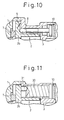
- Figs. 10 and 11 show a structure of the essential parts of the scroll-type compressor C1 of the first embodiment and the scroll-type compressor C2 of the second embodiment according to a modification constituting a third embodiment of the invention.
- the structure of Fig. 10 corresponds to the first embodiment (Figs. 1 and 2)
- the structure of Fig. 11 corresponds to the second embodiment (Fig. 9).
- the third embodiment has the feature in that it does not have a spring 14 for urging the plunger 8 or the plunger 30.
- the spring 14 according to the first and second embodiments constantly keeps the plunger 8 or 30 urged toward the control pressure chamber 10. In the 100 % capacity operation, therefore, the head portion of the plunger is retreated to a position completely out of contact with the guide holes.
- the head portion of the plunger remains in light contact with the guide holes even under the 100 % operation. Since the force acting on the movable scroll member 2 to rotate it is supported by the antirotation mechanism 7, however, the problem is not posed of a heavy load being imposed on the contact portion between the plunger head portion and the guide holes.
- the compressor according to the third embodiment operates substantially the same way as the compressor according to the first (or second) embodiment in the case where the 100 % capacity operation is turned to the 0 % capacity operation or the other way around.
- Figs. 12 to 15 show the configuration and the operation of a scroll-type compressor C4 according to a fourth embodiment of the invention.
- the feature of the fourth embodiment lies in that a plunger 36 having the shape shown in Fig. 14 is slidably inserted into each of cylinders 1a formed axially on the inner side surface of a front housing 1, and guide holes 36a, 36b constituting a two-stepped conical surface are formed in the end surfaces of the plunger 36.
- a guide pin 35 having a hemispherical head portion 35a engaging the guide holes 36a, 36b is arranged on the side of the end plate 2b of the movable scroll member 2.
- the bottom portion of the cylinder for receiving the plunger 36 is formed with a control pressure chamber 37 as a space, which communicates with a control valve 11 through a control pressure path 24a formed in the front housing 1 to connect a control pressure path 24.
- Several pairs, or specifically, about four pairs of the guide pin 35 and the plunger 36 can be arranged at equidistant positions around the shaft 5 as shown in the sectional view of Fig. 13 taken in line A-A in Fig. 12.
- a short cylindrical surface 36c is formed on the inlet side connected to each guide hole 36a.
- the compressor C4 is ready for 100 % capacity operation.
- the engagement between the cylindrical surface 36c and the guide pin 35 prevents the orbiting of the movable scroll member 2, and therefore the compressor C4 according to the fourth embodiment is not provided with the antirotation mechanism 7 unlike in the other embodiments described above.
- the operating condition at 0 % capacity of the scroll-type compressor C4 according to the fourth embodiment is shown in Fig. 15.
- the control valve 11 is switched to introduce the high discharge pressure into the control pressure chamber 37.
- the plunger 36 moves rightward in Fig. 12, and therefore the guide pin 35 is forcibly moved radially toward the center of the guide hole 36b.
- the movable scroll member 2 moves radially so that the amount of eccentricity and the orbiting radius are reduced.
- the discharge capacity is reduced substantially to zero, so that the internal pressure of the refrigeration cycle of the air-conditioning system is gradually equalized.
- the pressure of the control pressure chamber 37 decreases to a positive value near zero, only the urging force of the return spring 23 works in such a direction as to increase the amount of eccentricity and the orbiting radius of the movable scroll member 2 under the 0 % capacity operating condition as long as the pressure receiving area of the plunger 36 is set to a certain magnitude.
- the radial pressure F R and the centrifugal force F C generated in the compliance crankshaft mechanism 6 are zero, and therefore as long as the pressure of the control pressure chamber 37 assumes a positive value, the 0 % capacity operation can be maintained against the urging force of the return spring 23.
- the control valve 11 is switched to introduce a lower intake pressure (negative pressure) to the control pressure chamber 37.
- Figs. 16A and 16B show a configuration of the essential parts of the scroll-type compressor C4 according to a fifth embodiment as modified from the fourth embodiment of the invention.
- the feature of the fifth embodiment lies in the use of an annular plunger 39.
- an annular cylinder is arranged on the inner side surface of the front housing 1 to receive the annular plunger 39.
- An annular control pressure chamber is formed on the bottom of the annular cylinder and connected through the control pressure path 24 to the control valve 11.
- Guide holes including two-stepped conical surfaces 39a, 39b and a cylindrical surface 39c are formed at several equidistant positions on the annular plunger 38.
- a guide pin 35 protruded axially from the end plate 2b of the movable scroll member 2 is arranged in engagement with each of the guide holes.
- the annular plunger 39 is formed with holes 40, into each of which a pin (not shown) formed on the side surface of the front housing 1 is axially loosely inserted, thereby preventing the annular plunger 39 from rotating.
- the fifth embodiment uses the annular plunger 39, and therefore the effective area is increased. An axial force larger than in the fourth embodiment is generated, therefore, even by the low discharge pressure substantially zero at the 0 % capacity operation. Thus, the amount of eccentricity and the orbiting radius of the movable scroll member 2 can always be reduced zero and the stable 0 % capacity operation can be maintained.
- Fig. 17 shows a structure of the scroll-type compressor C according to a sixth embodiment of the invention.
- the essential parts of this compressor are shown in Fig. 18.
- the feature of the sixth embodiment lies in that the relative positions of the plunger head portions and the guide holes are opposite to each other.
- the guide holes 42 are formed in the end plate 2b of the movable scroll member 2, and each include two-stepped conical surfaces 42a, 42b and a cylindrical surface 42c.
- the plunger 43 is inserted into the cylinder formed on the front housing 1 so that each hemispherical head portion 43a at the forward end of the plunger 43 is adapted to engage corresponding one of the guide holes 42.
- the plunger 43 is shown in enlarged form in Fig. 18.
- the operation of the sixth embodiment is substantially similar to that of the fourth embodiment.
- Figs. 19A and 19B show a configuration of the essential parts of the scroll-type compressor C6 (Fig. 17) according to a seventh embodiment of the invention modified from the sixth embodiment.
- a single annular plunger 45 instead of a plurality of plungers, is used.
- the feature of the seventh embodiment is that a plurality of pins 47 are formed to protrude radially from the annular plunger 45, and the hemispherical head portion 47a at the forward end of each of the pins 47 is in engagement with the corresponding one of the guide holes 42 shown in Fig. 17.
- Fig. 19A and 19B show a configuration of the essential parts of the scroll-type compressor C6 (Fig. 17) according to a seventh embodiment of the invention modified from the sixth embodiment.
- a single annular plunger 45 instead of a plurality of plungers, is used.
- the feature of the seventh embodiment is that a plurality of pins 47 are formed to protrude radially from the annular plunger 45, and the
- reference numeral 46 designates holes into which pins not shown are inserted to block the rotation of the annular plunger 45.
- the compressor according to the seventh embodiment of which the general configuration is not shown, has a shape similar to Fig. 17. The operation of this embodiment is substantially the same as that of the fifth embodiment.
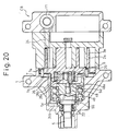
- Fig. 20 shows a structure of the scroll-type compressor C8 according to an eighth embodiment of the invention.
- the antirotation mechanism 7 is illustrated specifically as a mechanism including pins 7a and circular depressions 7b.
- Each of a plurality of the pins 7a and the corresponding one 7b of a plurality of the circular depressions 7b are paired with each other.
- Each one of the pins 7 is arranged on the end plate 2b of the movable scroll member 2, while the corresponding circular depression 7b is arranged on the front housing 1. Nevertheless, the relative positions of the pin 7a and the circular depression 7b may be opposite.
- the feature of the eighth embodiment lies in that the plunger 48 is inserted into the cylinder 5d formed on the boss portion 5c of the shaft 5, and the hemispherical head portion 48a at the forward end of the plunger 48 is in engagement with a guide hole including two-stepped conical surfaces 26b, 26c formed on an eccentric bushing 26.
- the conical surfaces 26b, 26c according to the eighth embodiment have a similar shape to the conical surfaces 9a, 9b of the guide hole 9 according to the first embodiment shown in Fig. 4. In Fig.
- numeral 49 designates a control pressure chamber formed on the bottom portion of the cylinder 5d for the plunger 48, and numeral 50 a shaft seal formed to prevent the leakage of the control pressure to the low-pressure intake side from the control pressure path 24b midway of the control pressure path 24 extending from the control valve 11 to the control pressure chamber 49.
- the operation of the compressor C8 according to the eighth embodiment is substantially similar to that of the fourth or sixth embodiment. According to the eighth embodiment, however, unlike in the first embodiment having such a structure that the guide hole 9, formed only at one point distant from the shaft 5, is pressed by the head portion 8a of the plunger 8, the guide hole formed in the eccentric bushing 26 at a position near the center of the movable scroll member 2 is pressed by the plunger 48, and therefore the whole movable scroll member 2 can be uniformly pressed. Thus, a smoother control operation is assured for changing the discharge capacity, thereby leading to a lesser likelihood of generating vibration.
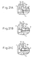
- Figs. 21A, 21B, 21C show a structure of the essential parts of the compressor according to a ninth embodiment of the invention and the operation thereof.
- a general configuration of this compressor is similar to that of the scroll-type compressor C1 according to the first embodiment shown in Fig. 1.
- the ninth embodiment is such that the surface of the guide hole 52 formed in the end plate 2b of the movable scroll member 2 is smoothly curved like a paraboloid of revolution or a hyperboloid of revolution.
- the angle between the surface of the engaged portion and the center axis of the shaft 5 increases steplessly.
- the discharge capacity can be controlled more smoothly than when the two-stepped conical surface is used.
- the scroll-type compressor C10 according to a tenth embodiment of the invention will be explained.
- the counterweight 5a is integrated with the boss portion 5c of the shaft 5, and therefore the vibration generated by the orbiting of the movable scroll member 3 could be suppressed, but the radial pressure generated by the centrifugal force acting on the movable scroll member 2 could not be suppressed.
- the shaft 5 is rotated at high speed with 100 % capacity, therefore, the centrifugal force acting on the movable scroll member 2 increases to such an extent that the spiral blade 2a is strongly pressed against the spiral blade 3a of the stationary scroll member 3.
- the resulting likelihood of wearing the blade surface poses the problem of the reduced reliability of the compressor operating under heavy load at high speed.
- the compressor C10 comprises a counter weight 54 as a part independent of the boss portion 5c of the shaft 5 and movable with respect to the latter.
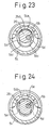
- the counter weight 54 as shown in Figs. 23 and 24, is partly formed with a large circular hole 54a for receiving the outer peripheral surface 26d of the end portion of the eccentric bushing 26 with a sufficient margin and allowing the eccentric bushing 26 to move in radial direction, a circular hole 54b sufficiently larger in diameter than the outer diameter of the boss portion 5c of the shaft 5 for receiving the outer peripheral surface 5e of the boss portion 5c with a margin, and a radial groove (called a bifacial groove) 54c having a predetermined width.
- a radial protrusion (called a bifacial protrusion) 5d having a predetermined width is formed at the end surface of the boss portion 5c of the shaft 5 and slidably engages the bifacial groove 54c of the counter weight 54.
- the other configuration is substantially similar to that of the scroll-type compressor C1 according to the first embodiment.
- the compressor C10 according to the tenth embodiment has the structure described above and, therefore, under the operating condition at 100 % capacity shown in Figs. 22 and 23, the eccentric bushing 26 and the counter weight 54 are rotated in operatively interlocked relation to each other with a part of the outer peripheral surface 26d of the eccentric bushing 26 in contact with a part of the inner surface of the circular hole 54a of the counter weight 54.
- the shaft 5 and the counter weight 54 are rotated in operatively interlocked relation with each other by the engaging portion between the bifacial protrusion 5d of the shaft 5 and the bifacial groove 54c of the counter weight 54, while the shaft 5 and the eccentric bushing 26 are rotated in operatively interlocked relation to each other by the eccentric pin 5b of the shaft 5 and the circular hole 54a of the counter weight 54 in contact with the outer peripheral surface 26d of the end portion of the eccentric bushing 26.
- the centrifugal force due to the orbiting motion is exerted on the movable scroll member 2.
- the force offsetting the centrifugal force is generated by the counter weight 54, and transmitted to the movable scroll member 2 from the contact point between the outer peripheral surface 26d of the end portion of the eccentric bushing 26 and the circular hole 54a of the counter weight 54.
- the counterweight 54 maintains the contact between the inner surface of the circular hole 54a and the outer peripheral surface 26d of the end portion of the eccentric bushing 26 until the inner surface of the circular hole 54b comes into contact with the outer peripheral surface 5e of the end portion of the boss portion 5c of the shaft 5.
- the bifacial groove 54c being in mesh with the bifacial protrusion 5d causes the counterweight 54 to slide radially with the eccentric bushing 26.
- the amount of eccentricity and the orbiting radius of the movable scroll member 2 are reduced.
- the intake pressure (negative pressure) is supplied to the control pressure chamber 10 by the control valve 11 as in the first embodiment.
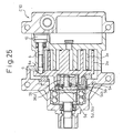
- the head portion 8a of the plunger 8 is retreated from the guide hole 9, so that the resultant force of the centrifugal force acting on the movable scroll member 2 and the pressure generated in the compliance crankshaft mechanism 6 causes the operating condition at 100 % capacity shown in Fig. 22 to be restored from the operating condition at 0 % capacity shown in Fig. 25.
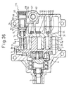
- numeral 60 designates a spool inserted slidably into the cylinder 58 arranged in parallel to the axis of the shaft 5 in a part of the housing 4, and numeral 61 a spring for urging the spool 60 in such a direction as to contract the second control pressure chamber 63 behind the spool 60.
- Numeral 62 designates a control valve for producing a control pressure of the required magnitude from the discharge pressure (high-pressure) and the intake pressure (low-pressure like a weak negative pressure) of the compressor C11, and supplying it to the second control pressure chamber 63 for the spool 60 and the control pressure chamber 10 having a similar configuration to that of the first embodiment.
- Numeral 64 designates a bypass hole open to an appropriate point of the end plate 3c of the stationary scroll member 3.
- the bypass hole 64 is provided with a check valve 65 with a protective valve stop plate 66 whereby the refrigerant contained in the compression chamber 15 at a pressure boosted to about an intermediate pressure between the discharge pressure and the intake pressure is released to the intermediate pressure chamber 67 of lower pressure, on the one hand, and the refrigerant is prevented from flowing in the opposite direction from the intermediate pressure chamber 67 to the compression chamber 15, on the other hand.
- Numeral 68 designates a control pressure path for leading the control pressure from the control valve 62 to the second control pressure chamber 63, and numeral 69 an intake pressure path for leading the intake pressure to the intermediate pressure chamber 67.
- the leftward movement of the spool 60 is blocked by a bar-shaped stopper 70.
- the spool 60 separates the control pressure chamber 10 and the second control pressure chamber 63 from each other.
- the spring 61 is also supported at the base end thereof by the stopper 70.
- the other configuration is substantially similar to that of the first embodiment shown in Fig. 1.
- the control valve 62 is operated in such a manner that the control pressure chamber 10 assumes an intake pressure and the second control pressure chamber 63 assumes a discharge pressure.
- the head portion 8a of the plunger 8 is urged by the spring 14 rearward away from the guide hole 9.
- the spool 60 is in such a position as to close the intake pressure path 69 since a high pressure prevails in the control pressure chamber 63.
- the pressure in the intermediate pressure chamber 67 increases to such an extent that the check valve 65 is not opened.
- the movable scroll member 2 orbits with the maximum orbiting radius to enter the 100 % capacity operation.
- the transfer to the 0 % capacity operation is carried out by supplying the discharge pressure to the control pressure chamber 10 from the control valve 62 substantially in the same manner as in the first embodiment.
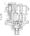
- the feature of the 11th embodiment is that the operating condition for causing the intermediate discharge capacity between the 100 % capacity and the 0 % capacity can be maintained in stable fashion.
- the intake pressure (weak negative pressure) is imparted to the second control pressure chamber 63 by operating the control valve 62.
- the spool 60 is moved rearward under the force of the spring 61 and opens the intake pressure path 69.
- the intake pressure of the control pressure chamber 10 is introduced into the intermediate pressure chamber 67, which thus assumes an intake pressure.
- the check valve 65 opens, so that the refrigerant of intermediate pressure that has thus far been contained in the compressor 15 is passed through a bypass hole 64 to the intake side, and therefore the discharge capacity is reduced to maintain the operation of intermediate capacity.
- the scroll-type compressor C11 according to the 11th embodiment can realize the operating condition of intermediate capacity as well as 100 % and 0 % capacity operations.
Landscapes
- Engineering & Computer Science (AREA)
- Mechanical Engineering (AREA)
- General Engineering & Computer Science (AREA)
- Rotary Pumps (AREA)
- Applications Or Details Of Rotary Compressors (AREA)
Abstract
Description
- The present invention relates to a displacement compressor used for compressing the refrigerant of an automotive air-conditioning system, or in particular to a scroll-type compressor.
- In an air-conditioning system of an automotive vehicle, for example, the need for an inexpensive, compact and lightweight refrigerant compressor and the fact that the electromagnetic clutch normally provided for transmitting or cutting off the driving force from an engine is expensive, bulky and heavy have led to the demand for a compressor of new type which requires no electromagnetic clutch. To meet this demand, a swash plate compressor has already been practically used, in which the discharge capacity can be changed from 100 % to 0 % by changing the inclination of the swash plate. However, a scroll-type compressor of which the discharge capacity can be reduced to 0 % has yet to be realized.
- For eliminating the electromagnetic clutch added to the scroll-type compressor, it is necessary that the scroll-type compressor can operate with 0 % capacity to reduce the discharge capacity thereof to zero in substantially the same manner as if the electromagnetic clutch is off on the one hand and that the power loss in operation is so small as to have no adverse effect on the fuel cost of the automotive vehicle on the other.
- To cope with this problem, the variable-capacity type refrigerant compressor of a scroll type described in Japanese Unexamined Patent Publication No. 5-231353 has been proposed in the prior art. In this compressor, a bypass is arranged between a compression chamber formed between a stationary scroll member and a movable scroll member and an intake chamber on the low-pressure side, and the discharge capacity is changed by opening/closing the bypass with a shuttle valve or the like. Since the compressed refrigerant cannot be fully returned to the intake chamber when the compressor is operating at high speed, however, it is difficult to achieve 0 % capacity.
- In what is called a combination system, having both a bypass from the compression chamber and a bypass from the discharge chamber where the compressed refrigerant is concentrated such as the scroll-type compressor described in Japanese Unexamined Patent Publication No. 4-179887, the following problem is posed. Specifically, in the operation at 0 % capacity, the entire amount of the refrigerant compressed is returned from the discharge chamber to the intake chamber and the orbiting radius of the movable scroll member is constant, so that the operation of 0 % capacity remains the same as with that of 100 % capacity. Therefore, the friction of the sliding parts is as large for 0 % capacity as for 100 % capacity, and the power loss in the 0 % capacity operation is increased to a not-negligible degree.
- Further, in the scroll-type compressor described in Japanese Unexamined Patent Publication No. 2-252990, not only the movable scroll member is moved but also the stationary scroll member is rotated relatively to the movable scroll member, and the crankshaft radius is made variable to assure smooth contact between the movable scroll member and the stationary scroll member. The mechanism in which the stationary scroll member is rotated as well as the movable scroll member, however, poses the problem that the structure is complicated and the compressor becomes bulky as a whole.
- The object of the present invention is to obviate the aforementioned problem of the prior art, using a novel means, and to provide a compact, lightweight and inexpensive scroll-type compressor in which not only the electromagnetic clutch is eliminated but also the power loss is minimized in the 0 % capacity operation by realizing a 0 % capacity operation.
- According to the invention, as a means for solving the problem described above, there is provided a scroll-type compressor described in
claim 1. - A scroll-type compressor according to the invention comprises a compliance crankshaft mechanism interposed between a shaft and a movable scroll member for allowing the orbiting radius of the movable scroll member to be reduced steplessly substantially to zero, wherein one of the movable scroll member and the housing is formed with a guide hole having an inclined surface with the depth thereof along the center axis of the shaft changing radially, and the other one of the movable scroll member and the housing not formed with the guide hole supports a plunger adapted to move toward and away from the guide hole to select a position to engage or not to engage the guide hole. The plunger is controlled by control means to advance and retract along the center axis of the shaft.
- When the plunger is advanced to the bottom portion of the guide hole, the position of the forward end of the plunger engaging the inclined surface of the guide hole so changes that the engagement changes to a higher position of the inclined surface. Thus, the movable scroll member is pushed down radially, and the center of the movable scroll member approaches and finally comes to coincide with the center of the stationary scroll member. Under this condition, the compression chamber formed between the spiral blade of the movable scroll member and the spiral blade of the stationary scroll member is open, and therefore the fluid like the refrigerant is not compressed. Thus, the operation capacity is reduced to 0 %, and even when the shaft is in rotation, the discharge amount is reduced substantially to zero. Under this operating condition, the compressor substantially fails to work, and therefore the power consumption is reduced substantially to zero even when the shaft is in rotation. Thus, the same condition is developed as if the electromagnetic clutch is deenergized.
- In another embodiment, a guide hole can alternatively be formed in the end plate of the movable scroll member, and the plunger is supported by the housing. Conversely, a guide hole may be formed in the plunger adapted to move by being supported on the housing, and a pin engaging the guide hole may be arranged on the end plate of the movable scroll member as another alternative. As still another alternative, a guide hole is formed in the eccentric bushing of the compliance crankshaft mechanism supporting the end plate of the movable scroll member, while at the same time supporting the plunger on the shaft journaled by the housing.
- A guide hole configured of a two-stepped conical surface can be reduced in depth. In the case where the guide hole is formed of a curved surface such as a quadratic surface of revolution, on the other hand, the same effect can be achieved smoothly as the two-stepped conical surface. Provision of energization means such as a spring for retreating the plunger completely from the position of engagement with the guide hole can always realize the operation of 100 % capacity. Nevertheless, the configuration can be simplified by omitting the energization means. Also, if the edge portion of the guide hole opening is formed with a cylindrical surface, on the other hand, the rotation of the movable scroll member can be prevented by use of the guide hole, and therefore the need of an antirotation mechanism is eliminated.
- One or several plungers may be provided. In the case where a single annular plunger is arranged in such a position as to surround the centerline of the shaft, the axial force can be generated against the guide hole uniformly around the shaft. Thus, the movable scroll member can be smoothly operated in radial direction, thereby making it possible to prevent vibration or the like.
- If a counter weight is mounted radially movably on the shaft with a bifacial portion, while the movable scroll member is moved radially in such a manner as to reduce the discharge capacity to zero, the counter weight that has thus far been in contact with the outer periphery of an eccentric bushing constituting a part of the compliance crankshaft mechanism comes into contact with the outer periphery of a large-diameter boss portion constituting a part of the shaft while leaving the outer periphery of the eccentric bushing from a predetermined time point. By configuring in this way, an excessively large pressure is prevented from being imparted between a pair of the spiral blades forming the compression chamber by the large centrifugal force exerted on the movable scroll member under a heavy-load, high-speed operating condition. In this way, the wear of the spiral blades can be suppressed.
- Further, in the case where a bypass adapted to establish communication between the compression chamber of intermediate pressure in the process of compression and the lower pressure side is opened to the end plate of the stationary scroll member and control means is provided for opening/closing the bypass, the compression chamber of intermediate pressure communicates with the low-pressure side when the bypass is opened by the control means. As a result, the discharge capacity is reduced, so that an intermediate discharge capacity between 100 % and 0 % can be achieved in stable fashion. In this way, the discharge capacity can be selectively controlled in three stages very easily.
- As described above, with the scroll-type compressor according to this invention, the operation of 0 % capacity with a very small power loss can be realized by reducing the orbiting radius of the movable scroll member to zero. Therefore, a scroll-type compressor with a variable discharge capacity free of the electromagnetic clutch can be provided.
-
- Fig. 1 is a longitudinal front view of a compressor operating at 100 % capacity according to a first embodiment of the invention.
- Fig. 2 is a longitudinal front view of a compressor operating at 0 % capacity according to a first embodiment of the invention.
- Fig. 3 is an exploded perspective view illustrating the structure of a compliance crankshaft mechanism.
- Fig. 4A is an enlarged longitudinal sectional view showing the 100 % capacity operation of the essential parts of the first embodiment, and Fig. 4B shows the process in transition to 0 % capacity.
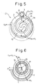
- Fig. 5 is a cross side view showing the relation between the forces exerted on a compressor operating at about 100 % capacity according to the first embodiment.
- Fig. 6 is a side view showing the eccentric bushing and the neighborhood thereof in the state shown in Fig. 5.
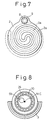
- Fig. 7 is a cross side view showing a compressor operating at 0 % capacity according to the first embodiment.
- Fig. 8 is a side view showing the eccentric bushing and the neighborhood thereof in the state shown in Fig. 7.
- Fig. 9 is a longitudinal front view of a compressor operating at 100 % capacity according to a second embodiment of the invention.
- Fig. 10 is a longitudinal sectional view showing the essential parts of a specific example of a third embodiment.
- Fig. 11 is a longitudinal sectional view showing the essential parts of another specific example of the third embodiment.
- Fig. 12 is a longitudinal front view showing a compressor operating at 100 % capacity according to a fourth embodiment of the invention.
- Fig. 13 is a cross sectional view taken in line A-A in Fig. 12, showing a compressor operating at 100 % capacity according to the fourth embodiment of the invention.
- Fig. 14 is an enlarged perspective view showing the essential parts of the fourth embodiment.
- Fig. 15 is a longitudinal front view of a compressor operating at 0 % capacity according to the fourth embodiment.
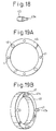
- Fig. 16A is an enlarged side view showing an annular plunger with guide pins both constituting the essential parts of a compressor according to a fifth embodiment, and Fig. 16B is a perspective view of the annular plunger.
- Fig. 17 is a longitudinal front view showing a compressor operating at 100 % capacity according to a sixth embodiment.
- Fig. 18 is a perspective view showing in enlarged form the essential parts the sixth embodiment of the invention.
- Fig. 19A is a side view showing in enlarged form an annular plunger constituting the essential parts of a compressor according to a seventh embodiment of the invention, and Fig. 19B a perspective view showing the same annular plunger with pins.
- Fig. 20 is a longitudinal front view of a compressor operating at 100 % capacity according to an eighth embodiment.
- Fig. 21A is a longitudinal sectional view showing the essential parts of a compressor operating at about 100 % capacity according to a ninth embodiment, Fig. 21B a diagram showing the discharge capacity being reduced according to the same embodiment, and Fig. 21C a diagram showing the same compressor operating at about 0 % capacity.
- Fig. 22 is a longitudinal front view showing a compressor operating at 100 % capacity according to a tenth embodiment.
- Fig. 23 is a cross side view taken in line B-B in Fig. 22, showing the essential parts of a compressor operating at 100 % capacity according to the tenth embodiment.
- Fig. 24 is a cross side view taken in line D-D in Fig. 25, showing the essential parts of a compressor operating at 0 % capacity according to the tenth embodiment.
- Fig. 25 is a longitudinal front view of a compressor operating at 0 % capacity according to the tenth embodiment.
- Fig. 26 is a longitudinal front view of a compressor operating at 100 % capacity according to an 11th embodiment.
- Fig. 27 is a cross side view taken in line E-E in Fig. 26, showing the essential parts of a compressor operating at 100 % capacity according to the 11th embodiment.
- Fig. 28 is a longitudinal front view showing a compressor operating at intermediate capacity according to the 11th embodiment.
-
- Figs. 1 and 2 show a general configuration of a scroll-type compressor C1 according to a first embodiment of the invention. Fig. 1 shows the compressor operating at 100 % capacity, and Fig. 2 shows the compressor operating at 0 % capacity. In Figs. 1 and 2,
reference numeral 1 designates a front housing, numeral 2 a movable scroll member orbitably supported in the housing, numeral 3 a stationary scroll member constituting a part of the housing, and numeral 4 a rear housing. Thefront housing 1, thestationary scroll member 2 and therear housing 4 are integrated by coupling means such as a through bolt, not shown, and constitute a single housing.Numeral 5 designates a drive shaft rotatably supported in thefront housing 1. A part of theshaft 5 is formed integrally with acounter weight 5a for suppressing the unbalanced vibrations caused by the orbital motion of themovable scroll member 2. -
Numeral 6 designates what is called a compliance crankshaft mechanism, which supports themovable scroll member 2 orbitably while allowing the amount of eccentricity of the center of themovable scroll member 2 with respect to theshaft 5, i.e. the orbiting radius of themovable scroll member 2 to change continuously. An example of the structure of this compliance crankshaft mechanism is shown in the perspective view of Fig. 3 as well as Figs. 1 and 2. Theboss portion 5c of theshaft 5 where thecounter weight 5a is mounted is formed integrally with aneccentric pin 5b extending along the axis in a position eccentric with respect to theshaft 5, whicheccentric pin 5b is rotatably inserted into theeccentric hole 26a formed eccentrically in the cylindricaleccentric bushing 26. Theeccentric bushing 26 rotatably supports, through aneedle bearing 20, thecylindrical boss portion 2c arranged on the back of the center of theend plate 2b of themovable scroll member 2. - Between the
boss portion 5c of theshaft 5 and theeccentric bushing 26, areturn spring 23 constituted of a coil spring or a spiral spring is mounted, and the ends of thereturn spring 23 are mounted on theboss portion 5c and theeccentric bushing 26. In this way, theboss portion 5c having theeccentric pin 5b of thecompliance crankshaft mechanism 6 and theeccentric bushing 26 make up a double eccentric mechanism. By selecting the direction in which thereturn spring 23 inserted between them is wound and applying a displacement beforehand to it, therefore, theboss portion 5c and theeccentric bushing 26 can be energized to rotate in opposite directions to each other. As a result, thereturn spring 23 constantly energizes themovable scroll member 2 radially outward in such a manner as to increase the orbiting radius and the amount of eccentricity of themovable scroll member 2 with respect to theshaft 5. The energizing force of thereturn spring 23 rotates theeccentric bushing 26 on theeccentric pin 5b of theshaft 5, so that the discharge capacity of the scroll-type compressor C1 restores to 100 % from 0 %. - Once the amount of eccentricity and the orbiting radius of the
movable scroll member 2 are established in this structure, theshaft 5 is rotated by the applied driving torque. Thus, thecompliance crankshaft mechanism 6 forces themovable scroll member 2 to orbit. At the same time, while the driving torque is transmitted through theeccentric bushing 26 and theeccentric pin 5b of thecompliance crankshaft mechanism 6 making up the double eccentric mechanism, and theeccentric pin 5b and theeccentric bushing 26 are relatively rotated in accordance with the magnitude of the transmitted torque. Thus, the amount of eccentricity and the orbiting radius of themovable scroll member 2 are increased, thereby generating pressure of a magnitude suitable for pressing thespiral blade 2a of themovable scroll member 2 against thespiral blade 3a of thestationary scroll member 3. Also, this operation is somewhat enhanced by thereturn spring 23. - The
component part 7 of which only the contour is shown in Figs. 1 and 2 is an antirotation mechanism always arranged normally in the scroll-type compressor and connects theend plate 2b of themovable scroll member 2 and thefront housing 1 to each other in such a manner as to allow themovable scroll member 2 only to orbit while preventing the rotation thereof without regard to the orbiting radius or the magnitude of themovable scroll member 2. - The greatest feature of the scroll-type compressor C1 according to the first embodiment lies in that a part of the outer shell of the
stationary scroll member 3 constituting a part of the housing is formed with asmall cylinder 3b along the axis into which theplunger 8 is slidably inserted. Thehemispherical head portion 8a of theplunger 8 is projected from thecylinder 3b and is in engaging contact with the inner surface of theguide hole 9 having two-stepped conical surface formed on theend plate 2b of themovable scroll member 2. In this case, as shown in Figs. 4A and 4B, the annular conical surface at the inlet around theguide hole 9 having a comparatively small sectional inclination angle with respect to the axis of theshaft 5 is designated as 9a, and the conical surface having a comparatively large inclination angle on the bottom portion of theguide hole 9 is designated as 9b. -
Numeral 10 designates a control pressure chamber formed as a space on the back of thedisk portion 8b formed at the rear end portion of theplunger 8.Numeral 11 designates a control valve for generating a control pressure to be imparted to thecontrol pressure chamber 10.Numeral 12 designates a discharge pressure path for introducing the discharge pressure (high-pressure) to thecontrol valve 11, numeral 13 an intake pressure path for introducing the intake pressure (low-pressure) similarly, and numeral 24 a control pressure path for introducing the control pressure from thecontrol valve 11 to thecontrol pressure chamber 10.Numeral 14 designates a spring for urging theplunger 8 rightward in Fig. 1 to keep thehead portion 8a of theplunger 8 and theguide hole 9 away from each other during the 100 % capacity operation. - As is well known, in the normal scroll-type compressor, numeral 15 designates a pair of compression chambers formed between the
spiral blade 2a of themovable scroll member 2 and thespiral blade 3a of thestationary scroll member 3 on the two radial sides with respect to the central portion, at which a single unified compression chamber 15a is formed of the particular pair of thecompression chambers 15. Adischarge valve 17, as a check valve, is arranged between the compression chamber 15a at the central portion and thedischarge chamber 16 formed as a space from the back of theend plate 3c of thestationary scroll member 3 to the interior of therear housing 4.Numeral 18 designates a valve stop plate for preventing thedischarge valve 17 from being excessively opened. -
Numeral 19 designates a bearing arranged on thefront housing 1 for journaling theshaft 5, and numeral 21 tip seals arranged along the forward end surface of the movable andstationary spiral blades compression chamber 15 toward the low-pressure side.Numeral 22 designates a shaft seal arranged to prevent the refrigerant from leaking outside from around theshaft 5. - The scroll-type compressor C1 according to the first embodiment has the structure described above and operates in the following way. First, as shown in Fig. 1, under the 100 % capacity operating condition that exhibits the maximum discharge performance of the compressor C1, the low intake pressure is introduced to the
control pressure chamber 10 by thecontrol valve 11. As a result, theplunger 8 is pushed rearward by thespring 14 so that thehead portion 8a of theplunger 8 is retreated to the position where it is out of engagement with theguide hole 9. Under this condition, thehead portion 8a has no operating effect on themovable scroll member 2. Therefore, themovable scroll member 2 assumes a maximum amount of eccentricity and, as in the normal scroll-type compressor, orbits with the maximum orbiting radius to produce the 100 % discharge capacity. The relative positions of thespiral blade 2a of themovable scroll member 2 and thespiral blade 3a of thestationary scroll member 3, and the relative positions of theplunger 8 and theguide hole 9 under the 100 % operation of the scroll compressor C1 are shown in the sectional view of Fig. 5. - As indicated by arrows in Fig. 5, the
spiral blade 2a of themovable scroll member 2 is pressed against thespiral blade 3a of thestationary scroll member 3 radially outward by the resultant force of the radial pressure FR generated by the relative rotation (including the relative rotation by the urging force of the return spring 23) of theeccentric bushing 26 around theeccentric pin 5b when thecompliance crankshaft mechanism 6 transmits the driving torque on the one hand and the centrifugal force FC generated by the orbiting of themovable scroll member 2 on the other hand. - As a result, the
compression chamber 15 is closed. Thus, when themovable scroll member 2 orbits and proceeds toward the central portion while being continuously contracted, the refrigerant introduced into the pair ofcompression chambers 15 from theintake chamber 25 on the outer peripheral portion is compressed and the pressure increases. The refrigerant thus merges into the single compression chamber 15a formed at the central portion and, opening thedischarge valve 17 under pressure, is discharged into thedischarge chamber 16. In this way, the compression reactive force FG is exerted on themovable scroll member 2 as a reaction of compression of the refrigerant in thecompression chamber 15. The magnitude of the compression reactive force FG and the magnitude of the pressure FR generated by thecompliance crankshaft mechanism 6 are correlated to each other. - The force for pressing the
spiral blade 2a of themovable scroll member 2 radially against thespiral blade 3a of thestationary scroll member 3 is primarily the resultant force of the radial pressure FR generated in thecompliance crankshaft mechanism 6 and the centrifugal force FC generated by the orbiting of themovable scroll member 2. This resultant force is indicated by the solid arrow in Fig. 6. Fig. 6 shows the operation at 100 % capacity. The radial force F2 as shown in Fig. 4A generated by the contact portion between theplunger 8 and theguide hole 9 is not yet generated. When theplunger 8 is activated to reduce the discharge capacity of the compressor C1 from 100 % capacity, however, the radial force F2 as indicated by the dashed arrow in Fig. 6 is generated and acts to offset the resultant force of the pressure FR and the centrifugal force FC described above. In Fig. 6, character C designates the center of thestationary scroll member 3, and character M the center of themovable scroll member 2. The amount of eccentricity represented by the distance between the centers C and M constitutes the orbiting radius R. - In the case where the scroll-type compressor C1 according to the first embodiment is operated with the 0 % discharge capacity constituting the feature of the invention, the refrigerant, at a high discharge pressure, is introduced from the
discharge chamber 16 to thecontrol pressure chamber 10 by the switching operation of thecontrol valve 11. As thedisk portion 8b receives the discharge pressure, theplunger 8 is pushed toward the front against the force of thespring 14, and as shown in Fig. 2, thehead portion 8a of theplunger 8 advances into theguide hole 9. Before the operation of 0 % capacity is reached as in Fig. 2, however, thehead portion 8a of theplunger 8 comes into contact with theconical surface 9a having a small inclination angle formed around theguide hole 9. - In the process, as shown in Fig. 4A, the axial force F1 determined by the magnitude of the discharge pressure and the pressure-receiving area of the
disk portion 8b of theplunger 8 is converted into the vertical (radial) force F2 for pushing themovable scroll member 2 in the direction perpendicular to the axis of theshaft 5, i.e. the force for reducing the discharge capacity toward 0 % at the contact point between thehead portion 8a of theplunger 8 and theconical surface 9a of theguide hole 9. Since the inclination angle of theconical surface 9a is comparatively small, the force F2 is amplified considerably with respect to the force F1. When this force F2 overcomes the resultant force of the radial pressure FR generated in thecompliance crankshaft mechanism 6 and the centrifugal force FC acting on themovable scroll member 2, theeccentric bushing 26 rotates about theeccentric pin 5b against the urging force of thereturn spring 23. As a result, themovable scroll member 2 is moved in radial direction in such a manner as to reduce the amount of eccentricity and hence the orbiting radius R of themovable scroll member 2. - Once the amount of eccentricity and the orbiting radius of the
movable scroll member 2 are reduced and theplunger 8 further moves toward the front side, thehead portion 8a of theplunger 8, as shown in Fig. 4B, comes into contact with the second-stepconical surface 9b on the bottom portion of theguide hole 9. The inclination angle of theconical surface 9b with respect to the axis of theshaft 5 is now larger than the inclination angle of theconical surface 9a. The vertical force F3 generated in the process, therefore, is now smaller than the force F2 shown in Fig. 4A. In view of the fact that the compression work is smaller with a smaller orbiting radius, however, the radial pressure is not substantially generated by thecompliance crankshaft mechanism 6. Also, the smaller amount of eccentricity reduces the centrifugal force exerted on themovable scroll member 2. Even in the case where the force F3 is small, therefore, themovable scroll member 2 can be moved in such a direction as to further reduce the amount of eccentricity and the orbiting radius. As a result, themovable scroll member 2 moves radially to the position where the center M thereof coincides with the center C of thestationary scroll member 3 and theshaft 5, thereby reducing the amount of eccentricity and the orbiting radius of themovable scroll member 2 to zero. - The 0 % capacity operation with the center of the
movable scroll member 2 moved radially in this way is shown in Fig. 2. Fig. 7 is a sectional view showing the positions of thespiral blade 2a of themovable scroll member 2 and thespiral blade 3a of thestationary scroll member 3, and the relative positions of theplunger 8 and theguide hole 9 under this operation condition. Under this condition, themovable scroll member 2 neither rotates nor orbits but is substantially stationary. - The force F3 generated when transferring from the 100 % capacity operation shown in Fig. 1 to the 0 % capacity operation shown in Fig. 2 is indicated by an arrow, for the convenience sake, in Fig. 5. The force F3 overcomes the resultant force of the pressure FR and the centrifugal force FC, so that the amount of eccentricity and the orbiting radius R of the
movable scroll member 2 are reduced to zero. Specifically, according as thehemispherical head portion 8a of theplunger 8 advances into theguide hole 9, the orbiting radius R and the amount of eccentricity of themovable scroll member 2 are progressively reduced. Thus, themovable scroll member 2 ceases to orbit, so that the centrifugal force FC due to the orbiting is reduced and finally becomes zero. On the other hand, thecompression chamber 15 formed between thespiral blades compliance crankshaft mechanism 6. This is also the case with the compression reaction FG. - Further, the resultant force of the centrifugal force FC and the pressure FR assumes a value approximate to zero. Thus, the force F3 generated in the contact portion between the
plunger 8 and theguide hole 9 against the resultant force increases beyond the particular resultant force. As a result, as shown in Fig. 8, the center M of themovable scroll member 2 comes to coincide with the center C of thestationary scroll member 3, so that the amount of eccentricity and the orbiting radius R of themovable scroll member 2 become zero and the compressor C1 enters the 0 % capacity operation. The radial force F3 is not so large. As long as the compressor C1 is in 0 % capacity operation, however, the radial force F3 is not reduced to zero as it works against the urging force of thereturn spring 23. - In the case where the
guide hole 9 is formed only of aconical surface 9a having a small inclination angle, the force F2 increases for moving themovable scroll member 2 in such a radial direction as to reduce the amount of eccentricity and the orbiting radius. In view of the fact that the radial movement of thescroll member 2 is small as compared with the axial movement of thehead portion 8a of theplunger 8, however, the need arises to increase the depth of theguide hole 9, thereby making it impossible to form theguide hole 9 within the thickness range of theend plate 2b of themovable scroll member 2. For this reason, the depth of theguide hole 9 is reduced by increasing the inclination angle of the second-stepconical surface 9b. In spite of this, at the position where thehead portion 8a engages theconical surface 9b, the orbiting radius is reduced, and the radial pressure FR of thecompliance crankshaft mechanism 6 assumes a small value of substantially zero and the centrifugal force FC exerted on themovable scroll member 2 is reduced. Therefore, even in the case where the force F3 is smaller than the force F2, themovable scroll member 2 can be moved in a radial direction. Also, this makes it possible to reduce the distance coverage of theplunger 8 in axial direction. - In the case where the scroll-type compressor C1 according to the first embodiment is used as a refrigerant compressor for the refrigeration cycle of the air-conditioning system, if the
plunger 8 advances deep into theguide hole 9 so that the amount of eccentricity and the orbiting radius R of themovable scroll member 2 become zero, and the discharge capacity of the compressor C1 decreases from 100 % to 0 %, even when the high-pressure upstream of the expansion valve in the refrigeration cycle gradually decreases to uniform pressure, the compressor C1 continues operating at the discharge capacity of 0 % as long as the axial force F1 generated by the pressure of thecontrol pressure chamber 10 received by thedisk portion 8b of theplunger 8 remains larger than the resultant force of the force of thespring 14 and thereturn spring 23. - In restoring the operation of the 100 % discharge capacity from this state again, the intake pressure (low-pressure) is introduced into the
control pressure chamber 10 by thecontrol valve 11. As a result, the urging force of thespring 14 moves theplunger 8 rearward. In thecompliance crankshaft mechanism 6, therefore, theeccentric bushing 26 and theneedle bearing 20 rotate about theeccentric pin 5b by the urging force of thereturn spring 23, thereby increasing the orbiting radius R and the amount of eccentricity of themovable scroll member 2. With the increase in the amount of eccentricity, the centrifugal force FC applied to themovable scroll member 2 increases. Thus, the amount of eccentricity and the orbiting radius R further increase with the result that the operation with the 100 % discharge capacity is restored. - As described above, with the scroll-type compressor C1 according to the first embodiment, the amount of eccentricity and the orbiting radius R of the
movable scroll member 2 can be easily and smoothly reduced to zero by adding a simple mechanism including theplunger 8 to the conventional scroll-type compressor. In the 0 % capacity operation, therefore, theneedle bearing 20, thebearing 19 and theshaft seal 22 constitute the only sliding or rolling portions, thereby realizing the 0 % capacity operation with a very small power loss. - Fig. 9 shows a structure of the scroll-type compressor C2 according to a second embodiment of the invention. This scroll-type compressor C2 is different from the scroll-type compressor C1 according to the first embodiment in that the relative positions of the
plunger 8 and theguide hole 9 are opposite to each other. Specifically, according to the second embodiment, theplunger 30 is thicker than theplunger 8 and has the forward end surface thereof formed withguide holes corresponding guide pin 31 is mounted on the side of theend plate 2b of themovable scroll member 2, and thehemispherical head portion 31a at the forward end of theguide pin 31 is adapted to engage theguide holes - Figs. 10 and 11 show a structure of the essential parts of the scroll-type compressor C1 of the first embodiment and the scroll-type compressor C2 of the second embodiment according to a modification constituting a third embodiment of the invention. The structure of Fig. 10 corresponds to the first embodiment (Figs. 1 and 2), and the structure of Fig. 11 corresponds to the second embodiment (Fig. 9). As compared with these embodiments, the third embodiment has the feature in that it does not have a
spring 14 for urging theplunger 8 or theplunger 30. Thespring 14 according to the first and second embodiments constantly keeps theplunger control pressure chamber 10. In the 100 % capacity operation, therefore, the head portion of the plunger is retreated to a position completely out of contact with the guide holes. According to the third embodiment lacking thespring 14, however, the head portion of the plunger remains in light contact with the guide holes even under the 100 % operation. Since the force acting on themovable scroll member 2 to rotate it is supported by theantirotation mechanism 7, however, the problem is not posed of a heavy load being imposed on the contact portion between the plunger head portion and the guide holes. - Although the general configuration of the compressor according to the third embodiment is not shown, as is obvious from the shown structure of the first and second embodiments, the compressor according to the third embodiment operates substantially the same way as the compressor according to the first (or second) embodiment in the case where the 100 % capacity operation is turned to the 0 % capacity operation or the other way around.
- Figs. 12 to 15 show the configuration and the operation of a scroll-type compressor C4 according to a fourth embodiment of the invention. The feature of the fourth embodiment lies in that a
plunger 36 having the shape shown in Fig. 14 is slidably inserted into each ofcylinders 1a formed axially on the inner side surface of afront housing 1, and guideholes plunger 36. Aguide pin 35 having ahemispherical head portion 35a engaging theguide holes end plate 2b of themovable scroll member 2. The bottom portion of the cylinder for receiving theplunger 36 is formed with acontrol pressure chamber 37 as a space, which communicates with acontrol valve 11 through acontrol pressure path 24a formed in thefront housing 1 to connect acontrol pressure path 24. - Several pairs, or specifically, about four pairs of the
guide pin 35 and theplunger 36 can be arranged at equidistant positions around theshaft 5 as shown in the sectional view of Fig. 13 taken in line A-A in Fig. 12. According to the fourth embodiment, a shortcylindrical surface 36c is formed on the inlet side connected to eachguide hole 36a. In the operating condition shown in Fig. 12 with thecylindrical surface 36c in engagement with theguide pin 35, therefore, the compressor C4 is ready for 100 % capacity operation. Under this operating condition, the engagement between thecylindrical surface 36c and theguide pin 35 prevents the orbiting of themovable scroll member 2, and therefore the compressor C4 according to the fourth embodiment is not provided with theantirotation mechanism 7 unlike in the other embodiments described above. Even under the operating condition of less than 100 %, thehemispherical head portion 35a of eachguide pin 35 in engagement with the conical surface of theguide holes plunger 36 prevents the orbiting of themovable scroll member 2. A similar configuration can be employed also for each of the embodiments described above, and therefore the provision of theantirotation mechanism 7 is not the essential requirement of the compressor according to the invention. - The operating condition at 0 % capacity of the scroll-type compressor C4 according to the fourth embodiment is shown in Fig. 15. For reducing the discharge capacity from the operating condition of 100 % capacity shown in Fig. 12 to the 0 % capacity operation, as in each of the embodiments described above, the
control valve 11 is switched to introduce the high discharge pressure into thecontrol pressure chamber 37. As a result, theplunger 36 moves rightward in Fig. 12, and therefore theguide pin 35 is forcibly moved radially toward the center of theguide hole 36b. At the same time, themovable scroll member 2 moves radially so that the amount of eccentricity and the orbiting radius are reduced. Finally, as shown in Fig. 15, thehemispherical head portion 35a of theguide pin 35 drops to the center of theguide hole 36b of theplunger 36. Thus, the amount of eccentricity and the orbiting radius of themovable scroll member 2 are reduced to zero, and the 0 % capacity operation is realized. - Under the 0 % capacity operation, the discharge capacity is reduced substantially to zero, so that the internal pressure of the refrigeration cycle of the air-conditioning system is gradually equalized. Even after the pressure of the
control pressure chamber 37 decreases to a positive value near zero, only the urging force of thereturn spring 23 works in such a direction as to increase the amount of eccentricity and the orbiting radius of themovable scroll member 2 under the 0 % capacity operating condition as long as the pressure receiving area of theplunger 36 is set to a certain magnitude. Thus, the radial pressure FR and the centrifugal force FC generated in thecompliance crankshaft mechanism 6 are zero, and therefore as long as the pressure of thecontrol pressure chamber 37 assumes a positive value, the 0 % capacity operation can be maintained against the urging force of thereturn spring 23. For increasing the discharge capacity again toward 100 % capacity, thecontrol valve 11 is switched to introduce a lower intake pressure (negative pressure) to thecontrol pressure chamber 37. - The provision of a plurality of pairs of the
guide pin 35 and theplunger 36 and the equidistant arrangement thereof around theshaft 5 as in the fourth embodiment make it possible to push theend plate 2b of themovable scroll member 2 uniformly along the axis. As compared with the first embodiment having only a pair of theplunger 8 and theguide hole 9, therefore, a smoother operation of controlling the discharge capacity is assured. Also, the smaller axial pressure per each point eliminates the likelihood of generating vibration when changing the discharge capacity, thereby improving the reliability of the compressor. - Figs. 16A and 16B show a configuration of the essential parts of the scroll-type compressor C4 according to a fifth embodiment as modified from the fourth embodiment of the invention. The feature of the fifth embodiment lies in the use of an
annular plunger 39. Though not shown, an annular cylinder is arranged on the inner side surface of thefront housing 1 to receive theannular plunger 39. An annular control pressure chamber is formed on the bottom of the annular cylinder and connected through thecontrol pressure path 24 to thecontrol valve 11. Guide holes including two-steppedconical surfaces cylindrical surface 39c are formed at several equidistant positions on the annular plunger 38. Aguide pin 35 protruded axially from theend plate 2b of themovable scroll member 2 is arranged in engagement with each of the guide holes. As shown in Fig. 16A, theannular plunger 39 is formed withholes 40, into each of which a pin (not shown) formed on the side surface of thefront housing 1 is axially loosely inserted, thereby preventing theannular plunger 39 from rotating. - The fifth embodiment uses the
annular plunger 39, and therefore the effective area is increased. An axial force larger than in the fourth embodiment is generated, therefore, even by the low discharge pressure substantially zero at the 0 % capacity operation. Thus, the amount of eccentricity and the orbiting radius of themovable scroll member 2 can always be reduced zero and the stable 0 % capacity operation can be maintained. - Fig. 17 shows a structure of the scroll-type compressor C according to a sixth embodiment of the invention. The essential parts of this compressor are shown in Fig. 18. As compared with the fourth embodiment (Fig. 12), the feature of the sixth embodiment lies in that the relative positions of the plunger head portions and the guide holes are opposite to each other. According to the sixth embodiment, the guide holes 42 are formed in the
end plate 2b of themovable scroll member 2, and each include two-steppedconical surfaces cylindrical surface 42c. On the other hand, theplunger 43 is inserted into the cylinder formed on thefront housing 1 so that eachhemispherical head portion 43a at the forward end of theplunger 43 is adapted to engage corresponding one of the guide holes 42. Theplunger 43 is shown in enlarged form in Fig. 18. The operation of the sixth embodiment is substantially similar to that of the fourth embodiment. - Figs. 19A and 19B show a configuration of the essential parts of the scroll-type compressor C6 (Fig. 17) according to a seventh embodiment of the invention modified from the sixth embodiment. In the seventh embodiment, as in the fifth embodiment (Fig. 16) described above, a single
annular plunger 45, instead of a plurality of plungers, is used. The feature of the seventh embodiment is that a plurality ofpins 47 are formed to protrude radially from theannular plunger 45, and thehemispherical head portion 47a at the forward end of each of thepins 47 is in engagement with the corresponding one of the guide holes 42 shown in Fig. 17. In Fig. 19,reference numeral 46 designates holes into which pins not shown are inserted to block the rotation of theannular plunger 45. The compressor according to the seventh embodiment, of which the general configuration is not shown, has a shape similar to Fig. 17. The operation of this embodiment is substantially the same as that of the fifth embodiment. - Fig. 20 shows a structure of the scroll-type compressor C8 according to an eighth embodiment of the invention. According to the eighth embodiment, the
antirotation mechanism 7 is illustrated specifically as amechanism including pins 7a andcircular depressions 7b. Each of a plurality of thepins 7a and the corresponding one 7b of a plurality of thecircular depressions 7b are paired with each other. Each one of thepins 7 is arranged on theend plate 2b of themovable scroll member 2, while the correspondingcircular depression 7b is arranged on thefront housing 1. Nevertheless, the relative positions of thepin 7a and thecircular depression 7b may be opposite. - The feature of the eighth embodiment lies in that the
plunger 48 is inserted into thecylinder 5d formed on theboss portion 5c of theshaft 5, and thehemispherical head portion 48a at the forward end of theplunger 48 is in engagement with a guide hole including two-steppedconical surfaces eccentric bushing 26. Theconical surfaces conical surfaces guide hole 9 according to the first embodiment shown in Fig. 4. In Fig. 20, numeral 49 designates a control pressure chamber formed on the bottom portion of thecylinder 5d for theplunger 48, and numeral 50 a shaft seal formed to prevent the leakage of the control pressure to the low-pressure intake side from thecontrol pressure path 24b midway of thecontrol pressure path 24 extending from thecontrol valve 11 to thecontrol pressure chamber 49. - The operation of the compressor C8 according to the eighth embodiment is substantially similar to that of the fourth or sixth embodiment. According to the eighth embodiment, however, unlike in the first embodiment having such a structure that the
guide hole 9, formed only at one point distant from theshaft 5, is pressed by thehead portion 8a of theplunger 8, the guide hole formed in theeccentric bushing 26 at a position near the center of themovable scroll member 2 is pressed by theplunger 48, and therefore the wholemovable scroll member 2 can be uniformly pressed. Thus, a smoother control operation is assured for changing the discharge capacity, thereby leading to a lesser likelihood of generating vibration. - Figs. 21A, 21B, 21C show a structure of the essential parts of the compressor according to a ninth embodiment of the invention and the operation thereof. A general configuration of this compressor is similar to that of the scroll-type compressor C1 according to the first embodiment shown in Fig. 1. Unlike in the embodiments described above, in which the guide hole has a two-stepped conical surface, the ninth embodiment is such that the surface of the
guide hole 52 formed in theend plate 2b of themovable scroll member 2 is smoothly curved like a paraboloid of revolution or a hyperboloid of revolution. As a result, when the state of Fig. 21A changes to the state of Fig. 21C through the state of Fig. 21B, i.e. according as thehead portion 8a of theplunger 8 engaging theguide hole 52 approaches the bottom portion of theguide hole 52, the angle between the surface of the engaged portion and the center axis of theshaft 5 increases steplessly. Thus, the discharge capacity can be controlled more smoothly than when the two-stepped conical surface is used. - Now, with reference to Figs. 22 to 25, the scroll-type compressor C10 according to a tenth embodiment of the invention will be explained. In each of the embodiments described above, the
counterweight 5a is integrated with theboss portion 5c of theshaft 5, and therefore the vibration generated by the orbiting of themovable scroll member 3 could be suppressed, but the radial pressure generated by the centrifugal force acting on themovable scroll member 2 could not be suppressed. In the harsh operating condition, theshaft 5 is rotated at high speed with 100 % capacity, therefore, the centrifugal force acting on themovable scroll member 2 increases to such an extent that thespiral blade 2a is strongly pressed against thespiral blade 3a of thestationary scroll member 3. The resulting likelihood of wearing the blade surface poses the problem of the reduced reliability of the compressor operating under heavy load at high speed. - In order to solve this problem, the compressor C10 according to the tenth embodiment comprises a
counter weight 54 as a part independent of theboss portion 5c of theshaft 5 and movable with respect to the latter. Thecounter weight 54, as shown in Figs. 23 and 24, is partly formed with a largecircular hole 54a for receiving the outerperipheral surface 26d of the end portion of theeccentric bushing 26 with a sufficient margin and allowing theeccentric bushing 26 to move in radial direction, acircular hole 54b sufficiently larger in diameter than the outer diameter of theboss portion 5c of theshaft 5 for receiving the outerperipheral surface 5e of theboss portion 5c with a margin, and a radial groove (called a bifacial groove) 54c having a predetermined width. - As a part corresponding to the
bifacial groove 54c formed in thecounter weight 54, a radial protrusion (called a bifacial protrusion) 5d having a predetermined width is formed at the end surface of theboss portion 5c of theshaft 5 and slidably engages thebifacial groove 54c of thecounter weight 54. The other configuration is substantially similar to that of the scroll-type compressor C1 according to the first embodiment. - The compressor C10 according to the tenth embodiment has the structure described above and, therefore, under the operating condition at 100 % capacity shown in Figs. 22 and 23, the
eccentric bushing 26 and thecounter weight 54 are rotated in operatively interlocked relation to each other with a part of the outerperipheral surface 26d of theeccentric bushing 26 in contact with a part of the inner surface of thecircular hole 54a of thecounter weight 54. Theshaft 5 and thecounter weight 54 are rotated in operatively interlocked relation with each other by the engaging portion between thebifacial protrusion 5d of theshaft 5 and thebifacial groove 54c of thecounter weight 54, while theshaft 5 and theeccentric bushing 26 are rotated in operatively interlocked relation to each other by theeccentric pin 5b of theshaft 5 and thecircular hole 54a of thecounter weight 54 in contact with the outerperipheral surface 26d of the end portion of theeccentric bushing 26. The centrifugal force due to the orbiting motion is exerted on themovable scroll member 2. Nevertheless, the force offsetting the centrifugal force is generated by thecounter weight 54, and transmitted to themovable scroll member 2 from the contact point between the outerperipheral surface 26d of the end portion of theeccentric bushing 26 and thecircular hole 54a of thecounter weight 54. - In the process of transferring from the operating condition at 100 % capacity shown in Figs. 22 and 23 to the operating condition at 0 % capacity shown in Figs. 24 and 25 as the result of reduction in discharge capacity, the
counterweight 54 maintains the contact between the inner surface of thecircular hole 54a and the outerperipheral surface 26d of the end portion of theeccentric bushing 26 until the inner surface of thecircular hole 54b comes into contact with the outerperipheral surface 5e of the end portion of theboss portion 5c of theshaft 5. In the process, thebifacial groove 54c being in mesh with thebifacial protrusion 5d causes thecounterweight 54 to slide radially with theeccentric bushing 26. Thus, the amount of eccentricity and the orbiting radius of themovable scroll member 2 are reduced. Once thecircular hole 54b of thecounterweight 54 comes into contact with the outerperipheral surface 5e of the end portion of theboss portion 5c, however, thecounterweight 54 is prevented from moving in radial direction. After that, therefore, theeccentric bushing 26 is rotated around theeccentric pin 5b, thereby additionally reducing the amount of eccentricity and the orbiting radius to zero. - As described above, as long as the position at which the
counterweight 54 moves out of contact with theeccentric bushing 26 and comes into contact with theboss portion 5c of theshaft 5 substantially coincides with the position where the centrifugal force generated by thecounter weight 54 is reduced below the centrifugal force generated by themovable scroll member 2, the intake pressure (negative pressure) is supplied to thecontrol pressure chamber 10 by thecontrol valve 11 as in the first embodiment. Thus, thehead portion 8a of theplunger 8 is retreated from theguide hole 9, so that the resultant force of the centrifugal force acting on themovable scroll member 2 and the pressure generated in thecompliance crankshaft mechanism 6 causes the operating condition at 100 % capacity shown in Fig. 22 to be restored from the operating condition at 0 % capacity shown in Fig. 25. - In this way, with the scroll-type compressor C10 according to the tenth embodiment, in the 100 % capacity high-speed operating condition, the excessive pressure which otherwise might be exerted by the centrifugal force between the
spiral blade 2a of themovable scroll member 2 and thespiral blade 3a of thestationary scroll member 3 is suppressed, thereby improving the reliability of the compressor. - Finally, with reference to Figs. 26 to 28, the scroll-type compressor C11 according to an 11th embodiment of the invention will be explained. In Figs. 26 to 28, numeral 60 designates a spool inserted slidably into the
cylinder 58 arranged in parallel to the axis of theshaft 5 in a part of thehousing 4, and numeral 61 a spring for urging thespool 60 in such a direction as to contract the secondcontrol pressure chamber 63 behind thespool 60.Numeral 62 designates a control valve for producing a control pressure of the required magnitude from the discharge pressure (high-pressure) and the intake pressure (low-pressure like a weak negative pressure) of the compressor C11, and supplying it to the secondcontrol pressure chamber 63 for thespool 60 and thecontrol pressure chamber 10 having a similar configuration to that of the first embodiment. -
Numeral 64 designates a bypass hole open to an appropriate point of theend plate 3c of thestationary scroll member 3. Thebypass hole 64 is provided with acheck valve 65 with a protectivevalve stop plate 66 whereby the refrigerant contained in thecompression chamber 15 at a pressure boosted to about an intermediate pressure between the discharge pressure and the intake pressure is released to theintermediate pressure chamber 67 of lower pressure, on the one hand, and the refrigerant is prevented from flowing in the opposite direction from theintermediate pressure chamber 67 to thecompression chamber 15, on the other hand.Numeral 68 designates a control pressure path for leading the control pressure from thecontrol valve 62 to the secondcontrol pressure chamber 63, and numeral 69 an intake pressure path for leading the intake pressure to theintermediate pressure chamber 67. The leftward movement of thespool 60 is blocked by a bar-shapedstopper 70. Thus, thespool 60 separates thecontrol pressure chamber 10 and the secondcontrol pressure chamber 63 from each other. Thespring 61 is also supported at the base end thereof by thestopper 70. The other configuration is substantially similar to that of the first embodiment shown in Fig. 1. - In the 100 % capacity operation shown in Fig. 26, the
control valve 62 is operated in such a manner that thecontrol pressure chamber 10 assumes an intake pressure and the secondcontrol pressure chamber 63 assumes a discharge pressure. Thus, thehead portion 8a of theplunger 8 is urged by thespring 14 rearward away from theguide hole 9. Thespool 60 is in such a position as to close theintake pressure path 69 since a high pressure prevails in thecontrol pressure chamber 63. As a result, the pressure in theintermediate pressure chamber 67 increases to such an extent that thecheck valve 65 is not opened. Thus, themovable scroll member 2 orbits with the maximum orbiting radius to enter the 100 % capacity operation. - The transfer to the 0 % capacity operation is carried out by supplying the discharge pressure to the
control pressure chamber 10 from thecontrol valve 62 substantially in the same manner as in the first embodiment. The feature of the 11th embodiment is that the operating condition for causing the intermediate discharge capacity between the 100 % capacity and the 0 % capacity can be maintained in stable fashion. For this purpose, the intake pressure (weak negative pressure) is imparted to the secondcontrol pressure chamber 63 by operating thecontrol valve 62. As a result, thespool 60 is moved rearward under the force of thespring 61 and opens theintake pressure path 69. Thus, the intake pressure of thecontrol pressure chamber 10 is introduced into theintermediate pressure chamber 67, which thus assumes an intake pressure. By doing so, thecheck valve 65 opens, so that the refrigerant of intermediate pressure that has thus far been contained in thecompressor 15 is passed through abypass hole 64 to the intake side, and therefore the discharge capacity is reduced to maintain the operation of intermediate capacity. In this way, the scroll-type compressor C11 according to the 11th embodiment can realize the operating condition of intermediate capacity as well as 100 % and 0 % capacity operations.
Claims (11)
- A scroll-type compressor comprising:a housing journaling a drive shaft;a stationary scroll member including an end plate fixed on said housing and a spiral blade around the center axis of said shaft;a movable scroll member including an end plate and a spiral blade forming a plurality of compression chambers by engaging said spiral blade and said end plate of said stationary scroll member, said movable scroll member being capable of orbiting around the center axis of said shaft;a compliance crankshaft mechanism interposed between said shaft and said movable scroll member for orbiting said movable scroll member by said shaft and allowing the orbiting radius of said movable scroll member to change steplessly downward substantially to zero;a guide hole formed in a selected one of said movable scroll member and said housing and having an inclined surface with the depth along the center axis of said shaft changing in a radial direction;a plunger supported on a selected one of said movable scroll member and said housing in which said guide hole is not formed and which is adapted to advance toward and retract from said guide hole to thereby assume a selected one of a position in engagement with said guide hole and a position out of engagement with said guide hole; andcontrol operation means for controlling said plunger to advance and retract along the center axis of said shaft.
- A scroll-type compressor according to claim 1,
wherein said guide hole is formed at the end plate of said movable scroll member and said plunger is supported on said housing. - A scroll-type compressor according to claim 1,
wherein said guide hole is formed in said plunger movably supported on said housing, and a pin engaging said guide hole is formed on the end plate of said movable scroll member. - A scroll-type compressor according to claim 1,
wherein said guide hole is formed in an eccentric bushing constituting a part of said compliance crankshaft mechanism supporting the end plate of said movable scroll member, and said plunger is supported on said shaft journaled by said housing. - A scroll-type compressor according to any one of claims 1 to 4,
wherein said guide hole has a two-stepped conical surface. - A scroll-type compressor according to any one of claims 1 to 5,
wherein said guide hole has a substantially quadratic surface of revolution. - A scroll-type compressor according to any one of claims 1 to 6, further comprising urging means for retreating said plunger completely out of engagement with said guide hole.
- A scroll-type compressor according to any one of claims 1 to 7,
wherein a cylindrical surface is formed at the edge portion of the opening of said guide hole. - A scroll-type compressor according to any one of claims 1 to 8,
wherein said plunger is a single annular unit arranged around the center axis of said shaft. - A scroll-type compressor according to any one of claims 1 to 9,
wherein a counter weight is mounted movably in radial direction on said shaft by a bifacial portion, and
wherein while said movable scroll member moves radially to reduce the discharge capacity to zero, said counterweight first in contact with the outer periphery of the eccentric bushing constituting a part of said compliance crankshaft mechanism comes away from the outer periphery of said eccentric bushing by being brought into contact with the outer periphery of a large-diameter boss portion constituting a part of said shaft upon the lapse of a predetermined time. - A scroll-type compressor according to any one of claims 1 to 10,
wherein a bypass hole for establishing communication between the compression chamber of intermediate pressure under compression and the low-pressure side is opened to the end plate of said stationary scroll member,
said compressor further comprising control means for controlling the opening/closing of said bypass hole.
Applications Claiming Priority (2)
| Application Number | Priority Date | Filing Date | Title |
|---|---|---|---|
| JP2000391245A JP4597358B2 (en) | 2000-12-22 | 2000-12-22 | Scroll compressor |
| JP2000391245 | 2000-12-22 |
Publications (3)
| Publication Number | Publication Date |
|---|---|
| EP1217213A2 true EP1217213A2 (en) | 2002-06-26 |
| EP1217213A3 EP1217213A3 (en) | 2003-05-14 |
| EP1217213B1 EP1217213B1 (en) | 2008-11-05 |
Family
ID=18857431
Family Applications (1)
| Application Number | Title | Priority Date | Filing Date |
|---|---|---|---|
| EP01130202A Expired - Lifetime EP1217213B1 (en) | 2000-12-22 | 2001-12-18 | Scroll-type compressor |
Country Status (5)
| Country | Link |
|---|---|
| US (1) | US6742996B2 (en) |
| EP (1) | EP1217213B1 (en) |
| JP (1) | JP4597358B2 (en) |
| CN (1) | CN1232732C (en) |
| DE (1) | DE60136437D1 (en) |
Cited By (3)
| Publication number | Priority date | Publication date | Assignee | Title |
|---|---|---|---|---|
| GB2455613A (en) * | 2007-12-13 | 2009-06-17 | Scroll Tech | Scroll machine with orbiting scroll hub engaging orbit limiting device. |
| JP2014098316A (en) * | 2012-11-13 | 2014-05-29 | Toyota Industries Corp | Scroll type compressor |
| EP2224134A4 (en) * | 2007-12-27 | 2015-04-22 | Mitsubishi Heavy Ind Ltd | SPIRAL COMPRESSOR |
Families Citing this family (14)
| Publication number | Priority date | Publication date | Assignee | Title |
|---|---|---|---|---|
| JP3874694B2 (en) * | 2002-04-26 | 2007-01-31 | 株式会社ジェイテクト | Oil pump device |
| JP5594846B2 (en) * | 2011-04-22 | 2014-09-24 | 株式会社ヴァレオジャパン | Scroll compressor |
| JP5561302B2 (en) * | 2012-03-29 | 2014-07-30 | 株式会社豊田自動織機 | Scroll compressor |
| EP2806165B1 (en) | 2013-05-22 | 2015-09-09 | Obrist Engineering GmbH | Scroll compressor and CO2 vehicle air conditioner with a scroll compressor |
| EP2806164B1 (en) | 2013-05-22 | 2015-09-09 | Obrist Engineering GmbH | Scroll compressor and CO2 vehicle air conditioner with a scroll compressor |
| JP6393115B2 (en) * | 2014-08-28 | 2018-09-19 | サンデンホールディングス株式会社 | Scroll type fluid machinery |
| TWI664351B (en) * | 2016-10-28 | 2019-07-01 | 黃星憲 | Transformer scroll compressor |
| JP6343328B2 (en) * | 2016-11-21 | 2018-06-13 | 日立ジョンソンコントロールズ空調株式会社 | Scroll compressor |
| KR102503234B1 (en) * | 2018-11-30 | 2023-02-24 | 한온시스템 주식회사 | Scroll compressor |
| CN111412137A (en) * | 2020-04-07 | 2020-07-14 | 刘小龙 | Spiral reverse-curve wheel oil pump with two ends penetrating through shaft |
| DE102021206432A1 (en) | 2021-06-22 | 2022-12-22 | Brose Fahrzeugteile SE & Co. Kommanditgesellschaft, Würzburg | scroll machine |
| CN116658420B (en) * | 2023-07-26 | 2023-09-22 | 无锡达希科技有限公司 | Movable vortex assembly and vortex compressor |
| CN120367797A (en) * | 2024-01-23 | 2025-07-25 | 罗伯特·博世有限公司 | Scroll compressor having a rotor with a rotor shaft having a rotor shaft with a |
| DE102024133742B3 (en) * | 2024-11-18 | 2026-01-22 | Deutsches Zentrum für Luft- und Raumfahrt e.V. | Scroll compressor with intermediate chamber for the expansion of a medium previously compressed in the scroll compressor |
Citations (3)
| Publication number | Priority date | Publication date | Assignee | Title |
|---|---|---|---|---|
| JPH02252990A (en) | 1989-03-28 | 1990-10-11 | Aisin Seiki Co Ltd | Scroll type compressor |
| JPH04179887A (en) | 1990-11-14 | 1992-06-26 | Mitsubishi Heavy Ind Ltd | Scroll type compressor |
| JPH05231353A (en) | 1992-02-18 | 1993-09-07 | Sanden Corp | Variable displacement scroll compressor |
Family Cites Families (13)
| Publication number | Priority date | Publication date | Assignee | Title |
|---|---|---|---|---|
| JPH065069B2 (en) | 1984-08-11 | 1994-01-19 | 株式会社豊田自動織機製作所 | Rising shock reduction mechanism in scroll type compressor |
| JPS62105389U (en) * | 1985-12-23 | 1987-07-04 | ||
| JPS63212789A (en) * | 1987-02-28 | 1988-09-05 | Sanden Corp | Variable capacity type scroll compressor |
| KR920006046B1 (en) * | 1988-04-11 | 1992-07-27 | 가부시기가이샤 히다찌세이사꾸쇼 | Scroll compressor |
| US5224849A (en) * | 1992-02-20 | 1993-07-06 | Arthur D. Little, Inc. | Compliance mounting mechanism for scroll fluid device |
| US5451146A (en) * | 1992-04-01 | 1995-09-19 | Nippondenso Co., Ltd. | Scroll-type variable-capacity compressor with bypass valve |
| US5490769A (en) * | 1993-01-15 | 1996-02-13 | Sanden International (U.S.A.), Inc. | Variable capacity scroll type fluid displacement apparatus |
| US5366359A (en) * | 1993-08-20 | 1994-11-22 | General Motors Corporation | Scroll compressor orbital scroll drive and anti-rotation assembly |
| JP3470385B2 (en) | 1994-04-27 | 2003-11-25 | 株式会社デンソー | Compressor |
| JPH08144969A (en) * | 1994-11-22 | 1996-06-04 | Nippon Soken Inc | Scroll type compressor |
| US5741120A (en) * | 1995-06-07 | 1998-04-21 | Copeland Corporation | Capacity modulated scroll machine |
| JPH09195957A (en) | 1996-01-17 | 1997-07-29 | Nippon Soken Inc | Scroll compressor |
| US6341945B1 (en) * | 1999-10-18 | 2002-01-29 | Scroll Technologies | Scroll compressor with reduced capacity at high operating temperatures |
-
2000
- 2000-12-22 JP JP2000391245A patent/JP4597358B2/en not_active Expired - Fee Related
-
2001
- 2001-12-17 US US10/015,910 patent/US6742996B2/en not_active Expired - Fee Related
- 2001-12-18 EP EP01130202A patent/EP1217213B1/en not_active Expired - Lifetime
- 2001-12-18 DE DE60136437T patent/DE60136437D1/en not_active Expired - Lifetime
- 2001-12-24 CN CNB011449403A patent/CN1232732C/en not_active Expired - Fee Related
Patent Citations (3)
| Publication number | Priority date | Publication date | Assignee | Title |
|---|---|---|---|---|
| JPH02252990A (en) | 1989-03-28 | 1990-10-11 | Aisin Seiki Co Ltd | Scroll type compressor |
| JPH04179887A (en) | 1990-11-14 | 1992-06-26 | Mitsubishi Heavy Ind Ltd | Scroll type compressor |
| JPH05231353A (en) | 1992-02-18 | 1993-09-07 | Sanden Corp | Variable displacement scroll compressor |
Cited By (6)
| Publication number | Priority date | Publication date | Assignee | Title |
|---|---|---|---|---|
| GB2455613A (en) * | 2007-12-13 | 2009-06-17 | Scroll Tech | Scroll machine with orbiting scroll hub engaging orbit limiting device. |
| US7686599B2 (en) | 2007-12-13 | 2010-03-30 | Scroll Technologies | Scroll compressor with device to limit orbit radius |
| GB2455613B (en) * | 2007-12-13 | 2013-03-20 | Scroll Tech | Scroll compressor with device to limit orbit radius |
| EP2224134A4 (en) * | 2007-12-27 | 2015-04-22 | Mitsubishi Heavy Ind Ltd | SPIRAL COMPRESSOR |
| JP2014098316A (en) * | 2012-11-13 | 2014-05-29 | Toyota Industries Corp | Scroll type compressor |
| EP2730742A3 (en) * | 2012-11-13 | 2016-11-23 | Kabushiki Kaisha Toyota Jidoshokki | Scroll compressor with rotation restriction mechanism |
Also Published As
| Publication number | Publication date |
|---|---|
| JP4597358B2 (en) | 2010-12-15 |
| US20020081224A1 (en) | 2002-06-27 |
| US6742996B2 (en) | 2004-06-01 |
| CN1232732C (en) | 2005-12-21 |
| JP2002195176A (en) | 2002-07-10 |
| EP1217213A3 (en) | 2003-05-14 |
| DE60136437D1 (en) | 2008-12-18 |
| CN1360152A (en) | 2002-07-24 |
| EP1217213B1 (en) | 2008-11-05 |
Similar Documents
| Publication | Publication Date | Title |
|---|---|---|
| EP1217213B1 (en) | Scroll-type compressor | |
| EP0969209B1 (en) | Scroll-type variable-capacity compressor | |
| CN100467870C (en) | scroll compressor | |
| CN103321895B (en) | Vane pump | |
| US5960697A (en) | Axial piston machine | |
| KR100277815B1 (en) | Variable capacity compressor | |
| JP2004100563A (en) | Scroll compressor | |
| JP2005315176A (en) | Piston variable displacement compressor | |
| KR102734905B1 (en) | Fluid pressure rotating apparatus and construction machinery | |
| JP2009092023A (en) | Variable displacement pump | |
| GB2154666A (en) | Rotary scroll-type fluid machine | |
| JP3569759B2 (en) | Variable capacity swash plate type hydraulic machine | |
| JPH05164044A (en) | Refrigerant gas suction guide structure in piston type compressor | |
| JP3470385B2 (en) | Compressor | |
| JP2692097B2 (en) | Scroll gas compressor | |
| US20050265855A1 (en) | Piston type compressor | |
| JP2001355583A (en) | Scroll compressor | |
| JPH07127583A (en) | Scroll type fluid machine | |
| EP1092871A2 (en) | Hollow swash plate compressor piston with bores | |
| KR100558705B1 (en) | Variable capacity swash plate compressor | |
| JP2000234595A (en) | Variable displacement type gas compressor | |
| JPH10159757A (en) | Capacity control scroll compressor | |
| CN115704458A (en) | Stepless speed change structure | |
| JPH0261374A (en) | Swing swash plate type compressor | |
| JP2001020854A (en) | Swash plate type hydraulic rotary machine |
Legal Events
| Date | Code | Title | Description |
|---|---|---|---|
| PUAI | Public reference made under article 153(3) epc to a published international application that has entered the european phase |
Free format text: ORIGINAL CODE: 0009012 |
|
| AK | Designated contracting states |
Kind code of ref document: A2 Designated state(s): AT BE CH CY DE DK ES FI FR GB GR IE IT LI LU MC NL PT SE TR |
|
| AX | Request for extension of the european patent |
Free format text: AL;LT;LV;MK;RO;SI |
|
| PUAL | Search report despatched |
Free format text: ORIGINAL CODE: 0009013 |
|
| AK | Designated contracting states |
Designated state(s): AT BE CH CY DE DK ES FI FR GB GR IE IT LI LU MC NL PT SE TR |
|
| AX | Request for extension of the european patent |
Extension state: AL LT LV MK RO SI |
|
| 17P | Request for examination filed |
Effective date: 20030613 |
|
| 17Q | First examination report despatched |
Effective date: 20030929 |
|
| AKX | Designation fees paid |
Designated state(s): DE FR IT |
|
| 17Q | First examination report despatched |
Effective date: 20030929 |
|
| GRAP | Despatch of communication of intention to grant a patent |
Free format text: ORIGINAL CODE: EPIDOSNIGR1 |
|
| RIC1 | Information provided on ipc code assigned before grant |
Ipc: F04C 18/02 20060101AFI20080408BHEP Ipc: F04C 28/18 20060101ALI20080408BHEP |
|
| GRAS | Grant fee paid |
Free format text: ORIGINAL CODE: EPIDOSNIGR3 |
|
| GRAA | (expected) grant |
Free format text: ORIGINAL CODE: 0009210 |
|
| AK | Designated contracting states |
Kind code of ref document: B1 Designated state(s): DE FR IT |
|
| REF | Corresponds to: |
Ref document number: 60136437 Country of ref document: DE Date of ref document: 20081218 Kind code of ref document: P |
|
| PLBE | No opposition filed within time limit |
Free format text: ORIGINAL CODE: 0009261 |
|
| STAA | Information on the status of an ep patent application or granted ep patent |
Free format text: STATUS: NO OPPOSITION FILED WITHIN TIME LIMIT |
|
| 26N | No opposition filed |
Effective date: 20090806 |
|
| PG25 | Lapsed in a contracting state [announced via postgrant information from national office to epo] |
Ref country code: IT Free format text: LAPSE BECAUSE OF NON-PAYMENT OF DUE FEES Effective date: 20091218 |
|
| PGFP | Annual fee paid to national office [announced via postgrant information from national office to epo] |
Ref country code: DE Payment date: 20121213 Year of fee payment: 12 |
|
| PGFP | Annual fee paid to national office [announced via postgrant information from national office to epo] |
Ref country code: FR Payment date: 20130107 Year of fee payment: 12 |
|
| REG | Reference to a national code |
Ref country code: DE Ref legal event code: R119 Ref document number: 60136437 Country of ref document: DE |
|
| REG | Reference to a national code |
Ref country code: FR Ref legal event code: ST Effective date: 20140829 |
|
| REG | Reference to a national code |
Ref country code: DE Ref legal event code: R119 Ref document number: 60136437 Country of ref document: DE Effective date: 20140701 |
|
| PG25 | Lapsed in a contracting state [announced via postgrant information from national office to epo] |
Ref country code: DE Free format text: LAPSE BECAUSE OF NON-PAYMENT OF DUE FEES Effective date: 20140701 |
|
| PG25 | Lapsed in a contracting state [announced via postgrant information from national office to epo] |
Ref country code: FR Free format text: LAPSE BECAUSE OF NON-PAYMENT OF DUE FEES Effective date: 20131231 |
|
| PGFP | Annual fee paid to national office [announced via postgrant information from national office to epo] |
Ref country code: IT Payment date: 20121221 Year of fee payment: 12 |
|
| PGRI | Patent reinstated in contracting state [announced from national office to epo] |
Ref country code: IT Effective date: 20141217 |