EP1216907A1 - Systèm de commande de freinage amélioré muni d'un servomoteur d'assistance et d'une réaction hydraulique. - Google Patents
Systèm de commande de freinage amélioré muni d'un servomoteur d'assistance et d'une réaction hydraulique. Download PDFInfo
- Publication number
- EP1216907A1 EP1216907A1 EP01403028A EP01403028A EP1216907A1 EP 1216907 A1 EP1216907 A1 EP 1216907A1 EP 01403028 A EP01403028 A EP 01403028A EP 01403028 A EP01403028 A EP 01403028A EP 1216907 A1 EP1216907 A1 EP 1216907A1
- Authority
- EP
- European Patent Office
- Prior art keywords
- piston
- control
- annular piston
- chamber
- pressure
- Prior art date
- Legal status (The legal status is an assumption and is not a legal conclusion. Google has not performed a legal analysis and makes no representation as to the accuracy of the status listed.)
- Withdrawn
Links
Images





Classifications
-
- B—PERFORMING OPERATIONS; TRANSPORTING
- B60—VEHICLES IN GENERAL
- B60T—VEHICLE BRAKE CONTROL SYSTEMS OR PARTS THEREOF; BRAKE CONTROL SYSTEMS OR PARTS THEREOF, IN GENERAL; ARRANGEMENT OF BRAKING ELEMENTS ON VEHICLES IN GENERAL; PORTABLE DEVICES FOR PREVENTING UNWANTED MOVEMENT OF VEHICLES; VEHICLE MODIFICATIONS TO FACILITATE COOLING OF BRAKES
- B60T13/00—Transmitting braking action from initiating means to ultimate brake actuator with power assistance or drive; Brake systems incorporating such transmitting means, e.g. air-pressure brake systems
- B60T13/10—Transmitting braking action from initiating means to ultimate brake actuator with power assistance or drive; Brake systems incorporating such transmitting means, e.g. air-pressure brake systems with fluid assistance, drive, or release
- B60T13/24—Transmitting braking action from initiating means to ultimate brake actuator with power assistance or drive; Brake systems incorporating such transmitting means, e.g. air-pressure brake systems with fluid assistance, drive, or release the fluid being gaseous
- B60T13/46—Vacuum systems
- B60T13/52—Vacuum systems indirect, i.e. vacuum booster units
- B60T13/573—Vacuum systems indirect, i.e. vacuum booster units characterised by reaction devices
-
- B—PERFORMING OPERATIONS; TRANSPORTING
- B60—VEHICLES IN GENERAL
- B60T—VEHICLE BRAKE CONTROL SYSTEMS OR PARTS THEREOF; BRAKE CONTROL SYSTEMS OR PARTS THEREOF, IN GENERAL; ARRANGEMENT OF BRAKING ELEMENTS ON VEHICLES IN GENERAL; PORTABLE DEVICES FOR PREVENTING UNWANTED MOVEMENT OF VEHICLES; VEHICLE MODIFICATIONS TO FACILITATE COOLING OF BRAKES
- B60T13/00—Transmitting braking action from initiating means to ultimate brake actuator with power assistance or drive; Brake systems incorporating such transmitting means, e.g. air-pressure brake systems
- B60T13/10—Transmitting braking action from initiating means to ultimate brake actuator with power assistance or drive; Brake systems incorporating such transmitting means, e.g. air-pressure brake systems with fluid assistance, drive, or release
- B60T13/24—Transmitting braking action from initiating means to ultimate brake actuator with power assistance or drive; Brake systems incorporating such transmitting means, e.g. air-pressure brake systems with fluid assistance, drive, or release the fluid being gaseous
- B60T13/46—Vacuum systems
- B60T13/52—Vacuum systems indirect, i.e. vacuum booster units
- B60T13/565—Vacuum systems indirect, i.e. vacuum booster units characterised by being associated with master cylinders, e.g. integrally formed
Definitions
- the present invention relates to control systems brake equipped with a booster.
- the brake servo control system allowing to generate a control pressure in a master - cylinder without having a system operator support the entire the pushing effort required.
- a system includes a means of operator-movable control from a rest position to a control position to activate the servomotor.
- a reaction means system for transmitting to the control means a reaction force varying according to the control pressure and directed towards the rest position of the control means, so that the operator can sense and modulate control pressure through of the control means.
- reaction medium is a deformable disc made of rubber.
- Such a reaction disc is likely to deterioration by fatigue, which has a drawback.
- the servomotor comprises a movable partition secured to the hollow cylinder, to transmit pneumatic force directly to the hollow cylinder and the reaction means is the push rod which slides tightly in the hollow cylinder.
- An elastic return means is arranged between the hollow cylinder and the pusher to push the latter towards the master - cylinder.
- the pusher also carries a valve capable of interrupting the communication between the respective interior volumes of the master- cylinder and hollow cylinder.
- the object of the invention is to provide a system of hydraulic reaction brake control of the above type which is improved, i.e. simplified to present a lower cost and / or having improved operational safety.
- control means comprises a control rod arranged behind the composite piston and movable according to said axial direction, the control rod being able to receive annular piston and to transmit the reaction force, the control rod being able to receive from said operator a force of control to move the control rod to the position of control and transmit the control force to the annular piston to generate, in combination with said assist force, the control pressure.
- the master cylinder has a duct intended to connect the primary chamber to a fluid reservoir for allow permanent fluid replenishment in the chamber primary, even for example in the event of a slight leak or in the event of wear significant or expansion due to the downstream temperature.
- the piston annular is then arranged so as to be moved by the rod control in the control position to a position in which the annular piston closes said conduit, in order to allow a increase in control pressure in the primary chamber.
- the annular piston according to the invention closes the duct directly under the action of force from the start of the race, regardless of the weather response of the actuator, and even in the event of failure of the servomotor. This feature reduces the establishment time of the control pressure in the primary chamber and therefore the time for response of the system, which increases its security.
- the composite piston has a transverse partition to define a reaction chamber separable from said primary chamber, said transverse partition being pierced with a communication orifice for to put in communication the primary room and the room of reaction, said communication port being open in a state of normal operation of the system, so the pressure in the reaction chamber is then substantially equal to the pressure of control in the primary chamber, the system comprising a means for closing said communication orifice in a state of system panic operation, so that the room of reaction is then isolated from the control pressure prevailing in the primary chamber.
- the annular piston is able to slide axially with respect to the central piston forwards under the action of the control force, the system being in said operating state normal when the annular piston shifts in the forward direction relative to the central piston is less than a maximum amplitude predetermined, the system being in said operating state of panic when the offset reaches said maximum amplitude, the piston central being able, in the panic operating state of the system, to receive the control force from the control rod to generate control pressure regardless of force assistance.
- said maximum amplitude of the offset towards the front of the annular piston corresponds to an abutment of the annular piston with respect to the central piston at the level of the partition transverse so as to close said2,000 of communication.
- the central piston extends towards a bottom of said bore beyond the piston annular and carries at its end before the transverse partition separating said primary chamber, located between the transverse partition and said bottom of the reaction chamber located between the transverse bulkhead and the annular piston, so that the annular piston is subjected to the pressure in the reaction chamber.
- said means for closing off the communication orifice includes a valve mounted in said orifice communication, said valve comprising a movable pusher axially in said opening between an open position, for which said orifice is open and a closed position, in which said pusher substantially seals said orifice waterproof, front end of annular piston in panic position being able to push the plunger back into the closed position.
- the valve may have a return spring resting between the partition transverse and the pusher for pushing said pusher towards its position opening.
- the transverse partition is fixed inside the annular piston, the piston central with a body sliding inside tightly of the annular piston behind said transverse partition, the central piston carrying a support extending in front of the central piston through said communication orifice, said means for closing the orifice of communication comprising a gasket fixed to said support at the front of said transverse partition and arranged so as to come into hermetic contact with the transverse partition around said orifice communication when the annular piston is in panic position.
- This provides a brake control system offering a panic mode of operation while having a particularly simple design, which ensures a good relationship between the performance of the system and its implementation costs.
- the reaction chamber is defined between the transverse bulkhead and the body of the central piston, the primary chamber comprising a portion of the interior of the piston annular located at the front of said transverse partition and in communication with the bore of the master cylinder.
- the support comprises a head sliding in a sealed manner in said annular piston at the front of said transverse bulkhead, said reaction chamber comprising a front space defined between said support head and said transverse partition, said primary chamber comprising a portion from the inside of the annular piston located at the front of said head support and in communication with the bore of the master cylinder, said support head being traversed by a channel opening behind said seal so as to connect said primary chamber to a intermediate chamber defined between said transverse partitions and said central piston.
- the primary chamber of the master cylinder is in communication with an interior volume of the annular piston extending to the transverse partition, which can be located at a level of the annular piston located outside the bore of the master cylinder. Therefore, the volume of the primary chamber is not not limited only by the volume of the master cylinder, so that the master cylinder can be shortened compared to designs classics.
- the advantages of a shortened master cylinder are multiple: reduction in the size of the control system braking, reduction in weight and cost of making the master cylinder.
- an elastic return means is provided. in said compressed front space between said support head and said transverse partition, so as to facilitate reopening of said communication orifice when the control force decreases.
- the interior of the annular piston has a rear stage in which said seal slides body of the central piston and, between said rear stage and said partition transverse, an intermediate stage in which slides so seals a head portion of said annular piston, said chamber intermediate being defined between said transverse partition and said head part of the annular piston.
- the intermediate stage of the piston ring has a smaller section than the rear floor and more as large as the communication port, said reaction chamber having a rear space defined between said body of the central piston and the rear stage of the annular piston, a connecting duct being formed in the wall of the annular piston to connect the front space and rear space.
- the assistance booster comprises a casing arranged behind the master cylinder, said casing being separated by a transverse wall, axially movable substantially sealed in said casing, in a low pressure chamber located at the front of the transverse wall, said low pressure chamber being connected to a vacuum source to maintain pressure there significantly lower than atmospheric pressure, and a work located at the rear of said transverse wall, the wall transverse being pierced with a communication channel between the working chamber and the low pressure chamber, the means of control being able to actuate selective closure means to, in the rest position of said control means, open said communication channel and close a passage between the working and the outside of the housing so that the actuator is then inactive, said low pressure also being established in the work and, at the control position of the control means, close off said communication channel and open said passage, to leave establish a pressure higher than said low pressure in the working chamber, the actuator then being activated, said wall transverse being linked to the central piston, to transmit the force to it pneumatic Fp assistance resulting from the difference between the pressures
- the control system includes a master cylinder 1 comprising a body 111 provided with an axial bore 2 of axis A in which is engaged a composite piston 3.
- a master cylinder 1 comprising a body 111 provided with an axial bore 2 of axis A in which is engaged a composite piston 3.
- the rear end 5 of the master cylinder 1 is open and opens into a casing 6 of a vacuum booster 7.
- the casing 6 is assembled in a sealed manner to the master cylinder 1.
- the master cylinder 1 further comprises elastic return means (springs) known to those skilled in the art, not shown here and located, by example, between piston 3 and a secondary piston 24 and between the piston secondary 24 and the master body 111-cylinder.
- the vacuum servomotor 7 conventionally comprises a transverse wall 8 movable axially in the casing 6 and separating this in a front chamber 9 called the low pressure chamber, which is connected to a vacuum source 41 to maintain a low pressure significantly below atmospheric pressure, and a rear chamber 10 known as the working chamber.
- the transverse wall 8 carries a rubber diaphragm 42 in contact with the casing 6 to sealingly separate the two chambers 9 and 10.
- the wall transverse 8 is assembled to an axially movable working piston 11 tightly through an opening in the rear face 12 of the housing 6.
- a plunger 13 is engaged axially through the piston motor 11 and can slide in leaktight manner with respect thereto.
- a control rod 15 has its front end linked to the plunger 13 and its rear end connected to a brake pedal 16 or to any other equivalent control means for moving it axially in order to control the system on foot or manually.
- the driving piston 11 carries a rubber valve 14 which cooperates with the plunger 13 to activate and deactivate the servomotor 7.
- the plunger 13 In the rest position of the system, shown in Figure 1, the rod 15 and the plunger 13 are moved back, the plunger 13 cooperates with the rubber valve 14 to, on the one hand, open a channel for communication 44 formed in the transverse wall 8 between the two chambers 9 and 10 and, on the other hand, isolate the working chamber 10 from outside air. Low pressure is then established in both chambers 9 and 10.
- the transverse wall 8 is maintained in the position of rest at the rear of the casing 6 by a return spring 17.
- the servomotor 7 is then passive.
- the composite piston 3 comprises an annular piston 18 axially movable in the body 111 of the master cylinder 1 and having an axial bore in which a primary piston 19 is also axially movable.
- the annular piston 18 has on its outer periphery a seal or a sealing cup 20 for ensure tight contact with the side wall 23 of the master cylinder 1.
- the primary piston 19 has a seal on its outer periphery seal 21 to ensure tight contact with the annular piston 18.
- the bore 2 of the master cylinder is divided by the movable secondary piston 24 in tight contact with the side wall 23 of the master cylinder 1 in a primary chamber 25 defined between the composite piston 3 and the secondary piston 24 and a secondary chamber 26 defined between the secondary piston 24 and the bottom 4.
- the primary chambers 25 and secondary 26 are filled with a substantially hydraulic fluid incompressible and are intended to be connected to control brakes hydraulic.
- the side wall 23 of the master cylinder has a conduit 27 which connects the primary chamber 25 to a reservoir 35, visible in FIG. 3.
- the hydraulic fluid in the tank 35 is for example subjected to a pressure substantially equal to atmospheric pressure.
- the duct 27 is open and the pressure established in the primary chamber is also atmospheric pressure.
- the plunger 13 passes through the driving piston 11 and is connected by its front end to the annular piston 18 to transmit the force to it Fm.
- the diver 13 has a rear end wall 131 to which is assembled the control rod 15 and a central part comprising a ring 130 extending forwards by several, for example three, arms 132 engaged axially through as many bores 45 of the engine pedestal 11 and each extended by a finger 133 projecting axially towards forward.
- the assembly between the plunger 13 and the annular piston 18 is achieved for example by a dog clutch between the fingers 133 of the plunger 13 and axial grooves 28 formed on the outer face of the piston annular 18 at its rear end.
- Each arm 132 can be surrounded a seal 46, visible in FIG. 3, for sliding from sealingly relative to the driving piston 11 in the bores 45.
- the driving piston 11 is connected to the primary piston 19 by a rigid piston rod 22 extending in the annular piston 18.
- the pneumatic force Fp is transmitted to the primary piston 19 which also advances in the primary chamber 25 to generate said control pressure P1.
- the control pressure P1 checks: P1.
- (S 18 S + 19 ) Fp + Fm, where S 18 and S 19 are the respective cross sections of the annular piston 18 and of the primary piston 19 in contact with the primary chamber 25.
- the choice of sections S 18 and S 19 therefore makes it possible to adjust the reduction between the pneumatic force Fp and the reaction force Fr.
- the reaction force Fr is transmitted by the annular piston 18 to the operator via the plunger 13, the control rod 15 and the brake pedal 16.
- the annular piston 18 thus fulfills the role of system reaction piston.
- the reaction force Fr allows the operator to control the control pressure P1.
- the primary piston 119 now has two successive parts in the axial direction: a first part 119 a of section substantially equal to the section of the bore 38 of the annular piston 18 and a second part 119 b of section substantially equal to the section of the bore 2 of the master cylinder body 1.
- the first part 119 a carries the seal 21 for sliding in leaktight manner in the bore 38 and extends forwards beyond the front edge 37 of the piston annular 18.
- the second part 119 b extends the first part 119 a towards the front and carries a seal 30 for sliding in leaktight manner in the bore 2.
- the second part 119 b of the primary piston 119 separates the bore 2 in a primary chamber 125 defined between itself and the movable secondary piston 24 and a reaction chamber 31 defined between itself and front edge 37 of the annular piston 18.
- the conduit 27 in the side wall 23 of the master cylinder 1 connects the hydraulic fluid reservoir 35 to the reaction chamber 31.
- the second part 119 b of the primary piston 119 has a communication orifice 32 between the chambers 125 and 31 in which is mounted a valve 34 for selectively closing the orifice 32.
- the valve 34 includes a pusher 343 arranged in the chamber 31 at the entrance to the orifice 32, facing the edge 37 of the annular piston 18, a rod 341 linked to the pusher 343 and engaged axially through the orifice 32 and a return spring 342 with one end in pressing against a shoulder of the orifice 32 and the other end pressing on a washer fixed to the rod 341, in order to push the rod 341 and the pusher 343 backwards, to an open position.
- the pusher 343 in the open position does not close the orifice 32, so that an equal pressure can be established in the chambers 125 and 31.
- any other selective closure means equivalent to the valve 34 could to be used.
- the control force Fm is intense, for example in the case of very urgent braking, the advance movement of the annular piston 18 is rapid and, during said delay, the central piston 119 not yet being moved by the servomotor 7, the annular piston 18 shifts forward relative to to the central piston 119 to a stop position, in which the opening of the passage 43 between the rubber valve 14 and the plunger 13 is maximum.
- the system is then in the operating mode of panic, as shown in Figure 5.
- the time lag between the annular piston 18 and the central piston 119 in panic position is on the order of 1.2 to 1.5 mm.
- the piston annular 18 pushes by its edge 37 the plunger 343 of the valve 34 to the closed position of said valve 34, thereby eliminating any communication between the reaction chamber 31 and the primary chamber 125.
- the annular piston 18 is then no longer subjected to the pressure of command P1 in primary chamber 125.
- a key 39 is linked to the plunger 13 and projects radially through the oblong hole 40 formed in the driving piston 11 to limit the axial offset between the plunger 13 and the driving piston 11.
- the oblong hole 40 also fulfills the function of air passage between the working chamber 10 and the axial bore of the driving piston 11, to put the working chamber 10 into communication with the outside air through the axial bore of the driving piston 11 when the servomotor is activated .
- the key 39 is free to move axially in the oblong hole 40.
- the key 39 is in abutment against the front edge of the oblong hole 40 to define the abutment position of the annular piston 18.
- the abutment piece of the annular piston 18 in the panic position could be the pusher 343 or the second part 119 b of the central piston 119.
- the control force intensity threshold separating the normal operating mode the operating mode of panic is predetermined based on the response time of the servomotor 7.
- a spring 36 prestressed in compression can be inserted in the annular piston 18 around the piston rod 22 with one end resting against the central piston 119 and another end resting on the annular piston 18 so as to adjust the level of said threshold.
- the spring 36 also increases the force of reaction Fr.
- control force Fm is transmitted to the central piston 119 to generate the control pressure P1 in the chamber primary 125 independently of the pneumatic force Fp, in particular before the pneumatic force Fp takes effect.
- the duct 27 is closed by the annular piston 18 is effective from the beginning of the movement of the annular piston 18 forwards, even before that it reaches its stop position. The increase in control pressure P1 in the primary chamber 125 is therefore substantially immediate.
- the system has a response time shorter than known arrangements, in which the obturation of a conduit between the primary chamber and a fluid reservoir 35 hydraulic is provided by a member linked to the servomotor, which increases system security.
- the control system of the third embodiment includes a master cylinder 201 provided an axial bore 202 of axis A.
- the rear end 205 of the master - cylinder 201 is open and opens into a casing 206 of a vacuum servo motor 207.
- the vacuum servo motor 207 is identical to the vacuum servomotor 7 described above with regard to its operation.
- the housing 206 of which only a lower half is shown, is assembled tightly to the master cylinder 201.
- the master cylinder 201 and the servomotor 207 are fixed on an apron 274 delimiting the front of the passenger compartment of a motor vehicle by fastening means well known to those skilled in the art and which are not shown.
- An annular piston 218 is engaged in the bore 202 and movable along axis A therein.
- the side wall 223 of the master cylinder 201 carries, on the inside of the bore 202, two cups 252 and 253, visible in Figure 9, to ensure contact watertight with the annular piston 218.
- the annular piston 218 has an axial bore 238 in which a transverse partition is arranged 247 pierced with an orifice 232.
- the body 248 of a primary piston 219 is also axially movable in leaktight manner in bore 238 behind the partition 247.
- the annular piston 218 and the primary piston 219 constitute a composite piston 203.
- the body 248 of the piston primary 219 has a seal on its outer periphery 221 to ensure leaktight contact with the annular piston 2 18.
- a primary chamber 225 is defined between the bottom 204 of the bore 202 and the transverse partition 247 in the annular piston 218.
- Primary chamber 225 is filled with hydraulic fluid substantially incompressible and is intended to be connected to brakes hydraulic control.
- a return spring 254 precaged by a tube telescopic 255 is housed in the primary chamber 225 with a end supported on the bottom 204 and the other end supported on the annular piston 218 to return the annular piston 218 backwards of the master cylinder 201.
- a reaction chamber 231 is defined in the bore 238 between the partition 247 and the body 248 of the primary piston 219.
- the side wall 223 of the master cylinder has a conduit 227 which opens into the primary chamber 225 behind the sealing cup 252 for connecting the primary chamber 225 to a hydraulic fluid reservoir 235 under pressure atmospheric, as visible in figure 9.
- the annular piston 218 presents at the right of the conduit 227 a passage 256 allowing the setting in communication of conduit 227 with primary chamber 225.
- a forward movement of the annular piston 218 causes an offset of the passage 256 and therefore a blockage of the conduit 227 by the annular piston 218.
- the transverse partition 247 is outside the master cylinder 201.
- the primary chamber 225 consists of a front portion 267 defined by bore 202 and a rear portion 250 defined at the inside of the bore 238 of the annular piston 218 up to the partition transverse 247.
- the volume of the primary chamber 225 is not limited by the length of the master cylinder 201.
- the master cylinder 201 can therefore be designed shorter than the master cylinder 1 previous embodiments.
- the plunger 213, of generally cylindrical shape, is mounted in a central bore 258 of the engine piston 211.
- the plunger 213 carries a seal 246 for sliding in a leaktight manner in the central bore 258.
- the annular piston 218 brings to its rear end a push rod 257 which is engaged through a hole 263 in the front wall 268 of the driving piston 211 so as to open into the central bore 258 of the engine piston 211.
- the plunger 213 is able to come into contact by its front end 233 with the thrust transmission rod 257 to transmit the control force Fm received from the rod control 215 to the annular piston 218.
- the driving piston 211 is connected to the primary piston 219 by a rigid piston rod 222 extending in the annular piston 218.
- the rod piston 222 has a flange 259.
- a spring 236 and an element of link 260 are engaged on the piston rod 222 between the flange 259 and the body 248 of the primary piston 219 to allow transmission of the pneumatic force Fp of the servomotor 207 from the engine piston 211 to the annular piston 218.
- the connecting element 260 has a transverse wall 262 bearing against a front end of the spring 236 and an external flange 261 bearing against one end rear of the annular piston 218.
- the body 248 of the primary piston 219 carries a rod support 249 extending forward through the orifice communication 232 which connects the reaction chamber 231 to the chamber primary 225.
- a rubber O-ring 234, visible in FIG. 9, is attached to a support head 264 at the end of the support rod 249 in the primary chamber 225 to allow closing the orifice of 232 communication in the panic operating mode of the control system.
- the support rod 249 is threaded and fixed by screwing in an axial bore 265 formed in the primary piston 219.
- the rear end of the rod piston 222 is retained in the front wall 268 of the engine piston 211 by a circlip 267.
- the rod thrust transmission 257 is designed as a separate part from the annular piston 218.
- a connecting piece 266 is fitted into the annular piston 218 at its rear end and the rod thrust transmission 257 is fixed to a transverse wall 269 of the connecting end piece 266.
- the transverse wall 269 also has an opening for the sliding rod to pass through piston 222.
- the duct 227 has an annular space formed between the internal face of the bore 202 of the master cylinder and the external face of an added piece 276 fixed in said bore.
- the tube pre-grading 255 in which the spring 254 is mounted is supported on the annular piston 218 via a support washer 277 fixed in bore 238.
- the system is in the rest position.
- the servo motor 207 is in the passive state.
- the low pressure imposed by the vacuum source 241 prevails in the two chambers 209 and 210 of the casing 206.
- the plunger 213 is in hermetic contact against the lip 271 of the rubber valve 214.
- the lip 271 of the rubber valve 214 is also kept in contact with the contour of the communication channel 244 by a valve spring 275.
- the hermetic contact of the lip 271 rubber valve 214 with the outline of the communication channel 244 is established only after balancing of the pressures in the two rooms 209 and 210.
- a space could remain open between the lip 271 of the rubber valve 214 and the contour of the channel communication 244 so as to maintain the two chambers 209 and 210 in communication via communication channel 244, the bore 258 and the oblong hole 240.
- the port 232 In the system rest position, the port 232 is open, the seal 234 not being in contact with the partition 247. Thus, the pressure in the primary chamber 225 and in the reaction chamber 231 is substantially equal.
- the conduit 227 is in communication with the primary chamber 225 through passage 256. Thus, the pressure in the primary chamber 225 and reaction chamber 231 is substantially atmospheric pressure.
- the engine piston 211 is held at a rear position of rest by a return spring 217. On the other hand, a space exists between the front end 233 of the plunger 213 and 1 a rod thrust transmission 257.
- the time required to close the line 227 depends only on the advance speed of the piston annular 218, and therefore of the control rod 215.
- the time of response of actuator 207 does not influence.
- the annular piston 218 performs the function of the system's reaction piston.
- the pressure P1 is exerted equally on the two faces of the transverse partition 247 so that no force results on the piston 218.
- the reaction force Fr is transmitted from the annular piston 218 to the operator via the thrust transmission rod 257, the plunger 213 and the control rod 215 to allow the operator to control the control pressure P1.
- the control pressure P1 during braking depends on the intensity of the control force Fm and reaches, for example, a value of the order of 30 bar.
- the annular piston 218 shifts towards the front relative to the primary piston 219 to a position in which the transverse partition 247 abuts against the support head 2 64 so that the seal 234 comes into hermetic contact around port 232, thereby closing the communication between the reaction 231 and the primary chamber 225.
- the system is then in mode of panic operation.
- the offset between the piston annular 218 and the primary piston 219 in panic position is 1.2 to 1.5 mm.
- the plunger 213 transmits the control force Fm to the engine piston 211 and therefore to the primary piston 219 via key 239 and rod piston 222. Therefore, the primary piston 219 receives the force of control from the control rod 215 via the key 239.
- the control force Fm is transmitted to the primary piston 219 to generate the control pressure P1 in the primary chamber 225 independently of the pneumatic force Fp, in particular before let the pneumatic force Fp take effect.
- the shuttering of the conduit 227 by the annular piston 218 is effective from the start of the displacement of the annular piston 218 forwards, even before it reaches its stop position.
- the increase in pressure command P1 in the primary chamber 225 is therefore substantially immediate.
- the transmission of the control force Fm with the primary piston 219 can be done between the partition 247 and the head of support 264.
- the control force Fm does not need to be transmitted via key 239, provided that provide a sufficiently solid design of the support 264.
- the operator reduces the intensity of the control force Fm.
- the annular piston 218 moves back relative to the central piston 219, which interrupts the contact between the seal 234 and the partition 247 and reopens the communication orifice 232.
- the system then returns to normal operating mode . It is desirable to correctly set the control force threshold below which the system returns to normal operating mode. Indeed, if this threshold is too high, for example greater than 60 daN, the operator is unable to apply a control force Fm sufficiently intense to remain in panic mode, which makes this mode unstable.
- this exit threshold is chosen too low, for example less than 5 daN, the operator risks not succeeding in exiting panic mode, which can lead to braking more intense than actually desired and to untimely immobilization of the vehicle.
- the exit threshold is chosen between 5 and 60 daN, preferably between 20 and 50 daN and even more preferably around 25 daN. This adjustment is obtained by the choice of the spring 254 and by the adaptation of the section S 234 sealed by the seal 234.
- the force of the spring 234 is 8 to 10 daN and the control pressure P1 is approximately 50 bar.
- the pressing force must not exceed 15 daN, which requires S p ⁇ 0.3 cm 2 .
- the annular wall of the piston 218 is designed to be of small thickness and the support head 264 is designed so as to occupy substantially the entire internal section of the annular piston 218 and to carry the seal 234 along its edge.
- the support head 264 occupies all of the inner section of the annular piston 218 and carries on its edge device a sealing cup 278 which slides so watertight in bore 238 in front of transverse partition 247.
- the central piston 219 for its part has a head portion 279 which extends to the front of body 248 and has a smaller section than the body 248.
- the bore 238 of the annular piston 218 present behind the transverse partition 247 an intermediate stage adjacent thereto and whose section is larger than the section of the orifice of communication 232 and smaller than the rear floor section of the bore 238 in which the piston body 248 slides so waterproof.
- the intermediate floor has a section adapted to that of the head part 279 and carries a sealing cup 280.
- the part head 279 of the central piston 219 slides tightly in the intermediate stage of the annular piston 218.
- the internal bore 238 of the annular piston 218 is divided into three.
- the rear portion 250 of the primary chamber is located at the front of the support head 264 and in communication with the bore of the master cylinder, a rear space 285 is delimited between the body of piston 248 and the intermediate stage of the annular piston 218, and a intermediate volume is delimited between the support head 264 and the face front of the central piston 219.
- This intermediate volume is itself separable in two in the panic operating mode.
- Support head 264 carries the O-ring 234 on its rear face opposite the face front of the partition 247 at the periphery of the orifice 232.
- the forward shift of the annular piston 218 relative to the central piston 219 causes contacting hermetic of the partition 247 against the joint 234.
- the volume intermediate is then separated into a front space 283 located outside the seal 234 between the support head 264 and the transverse partition 247, and an intermediate chamber 281 defined between the portion of the head of support 264 located inside the seal 234 and the head portion 279.
- the support head 264 is crossed by a channel 282 which opens behind seal 234 and connects the primary chamber 225 to the intermediate chamber 281.
- the intermediate chamber 281 is always subjected to the same control pressure P1 as the primary chamber 225.
- a connecting duct 286 is formed axially in the wall of the annular piston 218 at the level of the partition 247 and the intermediate floor to connect the e space before 283 and the rear space 285, which jointly form the system reaction.
- the room primary 225, intermediate chamber 281 and reaction chamber 283/285 are at the same pressure.
- the reaction chamber is isolated by seal 234 of the chamber intermediate 281 and therefore of the control pressure P1.
- the intensity threshold of the control force Fm from which the system returns to the normal operating mode after braking in panic mode can be calculated in the same way as in the previous case.
- section S 279 therefore partially or totally compensates for the contribution of the pressure P1 to the reaction force Fr, which facilitates the adjustment of the Panic mode exit threshold. It is also noted that in this variant, the section S 234 sealed by the seal 234 contributes in the opposite direction with respect to the embodiment of FIG. 9.
- a small helical spring 284 is housed in the front space 283 around the seal 234 and compressed between the head of support 264 and bulkhead 247 to ensure the system exits actually from panic mode when the command force decreases enough.
- the embodiments of the invention described above provide brake control systems in which the actuator in the activated state is capable of exerting the assistance force on the central piston, both in the normal operating mode of the system than in panic mode of operation, when a panic operating mode is expected.
- This assistance force tends to increase the control pressure in the master cylinder.
- the annular piston is able to transmit the reaction force to the control means as well in the normal operating mode of the system than in the mode of panic operation, when an operating mode of panic is expected.
- the systems described above employ a servo motor with depression.
- a pneumatic servomotor can also be used in place of the vacuum actuator.
- the master cylinder can identically be single-circuit, double-circuit as described above above, or two parallel circuits.
Landscapes
- Engineering & Computer Science (AREA)
- Transportation (AREA)
- Mechanical Engineering (AREA)
- Braking Systems And Boosters (AREA)
Abstract
Description
- un maítre-cylindre présentant un alésage ouvert sur une extrémité, dite arrière, dudit maítre-cylindre,
- un piston composite engagé dans ledit alésage pour générer une pression de commande dans un volume intérieur dudit maítre -cylindre, ledit piston composite comprenant un cylindre creux déplaçable de manière étanche dans le maítre-cylindre selon sa direction axiale et un poussoir mobile axialement de manière étanche dans le cylindre creux, le volume intérieur étant situé entre le piston composite et une paroi de fond et étant rempli d'un fluide sensiblement incompressible destiné à transmettre ladite pression de commande à au moins un frein à commande hydraulique,
- un moyen de commande déplaçable par un opérateur entre au moins une position de commande pour activer le servomoteur d'assistance et une position de repos dans laquelle le servomoteur d'as sistance est à l'état passif.
- un maítre-cylindre présentant un alésage ouvert sur une extrémité, dite arrière, dudit maítre-cylindre,
- un piston composite mobile selon une direction axiale de l'alésage pour générer une pression de commande dans une chambre primaire du maítre-cylindre, ledit piston composite comprenant un piston annulaire engagé dans ledit alésage et déplaçable de manière étanche dans l'alésage selon sa direction axiale et un piston central mobile axialement de manière étanche dans ledit piston annulaire,
- un moyen de commande déplaçable par un opérateur entre au moins une position de commande pour activer ledit servomoteur d'assistance et une position de repos dans laquelle le servomoteur d'assi stance est à l'état passif,
- la figure 1 est une vue en coupe axiale d'un premier mode de réalisation de système selon l'invention, le moyen de commande manuel étant en position de repos ;
- la figure 2 est une vue analogue à la figure 1 avec le moyen de commande manuel en position de commande ;
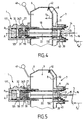
- la figure 3 est une vue en coupe axiale d'un deuxième mode de réalisation de système selon l'invention, le moyen de commande manuel étant en position de repos ;
- la figure 4 est une vue analogue à la figure 3 avec le moyen de commande manuel en position de commande, le système étant en état de fonctionnement normal ;
- la figure 5 est une vue analogue à la figure 3 avec le moyen de commande manuel en position de commande, le système étant en état de fonctionnement de panique ;
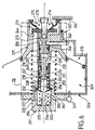
- la figure 6 est une vue en coupe axiale d'un troisième mode de réalisation de système selon l'invention, en position de repos ;
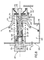
- la figure 7 représente le système de la figure 6 en état de fonctionnement normal ;
- la figure 8 représente le système de la figure 6 en état de fonctionnement de panique ;
- la figure 9 est une vue de détail du système de la figure 6 définie par le cadre IX, mais selon un plan de coupe perpendiculaire au plan de la figure 6,
- la figure 10 représente une variante du troisième mode de réalisation de système selon l'invention, en position de repos, en vue partielle agrandie définie par le cadre X de la figure 9.
où S279 est la section de la partie de tête 279 du piston central 219. Le choix de la section S279 permet donc de compenser partiellement ou totalement la contribution de la pression P1 à la force de réaction Fr, ce qui facilite le réglage du seuil de sortie du mode panique. On note aussi que dans cette variante, la section S234 scellée par le joint 234 contribue en sens opposé par rapport au mode de réalisation de la figure 9.
Claims (17)
- Système de commande de freinage muni d'un servomoteur d'assistance (7, 207), ledit système de commande comportant :caractérisé par le fait que le servomoteur d'assistance est agencé pour exercer, à l'état activé, sur ledit piston central (19, 119, 219), une force d'assistance (Fp) afin de générer ladite pression de commande (P1), ledit piston annulaire (18, 218) étant apte, sous l'action de ladite pression de commande (P1), à transmettre audit moyen de commande (15, 215) une force de réaction (Fr) orientée vers ladite position de repos.un maítre-cylindre (1, 201) présentant un alésage (2, 202) ouvert sur une extrémité (5, 205), dite arrière, dudit maítre -cylindre,un piston composite (3, 203) mobile selon une direction axiale (A) de l'alésage (2, 202) pour générer une pression de commande (P1) dans une chambre primaire (25, 125, 225) du maítre-cylindre (1), ledit piston composite comprenant un piston annulaire (18, 218) engagé dans ledit alésage et déplaçable de manière étanche dans l'alésage (2, 202) selon sa direction axiale (A) et un piston central (19, 119, 219) mobile axialement de manière étanche dans ledit piston annulaire (18, 218),un moyen de commande (15, 215) déplaçable par un opérateur entre au moins une position de commande pour activer ledit servomoteur d'assistance (7, 207) et une position de repos dans laquelle le servomoteur d'assistance est à l'état passif,
- Système selon la revendication 1, caractérisé par le fait que ledit moyen de commande comporte une tige de commande (15, 215) agencée derrière le piston composite (3) et mobile selon ladite direction axiale (A), ladite tige de commande étant apte à recevoir du piston annulaire (18, 218) et à transmettre audit opérateur ladite force de réaction (Fr), ladite tige de commande étant apte à recevoir dudit opérateur une force de commande (Fm) orientée sensiblement vers l'avant pour déplacer la tige de commande vers la position de commande et à transmettre au piston annulaire ladite force de commande (Fm) pour générer, en combinaison avec la force d'assistance (Fp), ladite pression de commande (P1).
- Système selon la revendication 2, caractérisé par le fait que ledit maítre-cylindre (1, 201) comporte un conduit (27, 227) destiné à relier ladite chambre primaire (25, 125, 225) à un réservoir de fluide (35, 235) pour maintenir un volume de fluide dans la chambre primaire, ledit piston annulaire (18, 218) étant agencé de manière à être déplacé par la tige de commande dans ladite position de commande à une position dans laquelle ledit piston annulaire obture ledit conduit (27, 227), afin de permettre une augmentation de ladite pression de commande (P1) dans ladite chambre primaire.
- Système selon la revendication 2 ou 3, caractérisé par le fait que ledit piston composite (3, 203) comporte une cloison transversale (119b, 247) pour définir une chambre de réaction (31, 231) séparable de ladite chambre primaire (125, 225), ladite cloison transversale étant percée d'un orifice de communication (32, 232) pour mettre en communication ladite chambre primaire et ladite chambre de réaction, ledit orifice de communication étant ouvert dans un état de fonctionnement normal dudit système, de sorte que la pression dans ladite chambre de réaction est alors sensiblement égale à la pression de commande (P1) dans ladite chambre primaire, ledit système comportant un moyen pour obturer ledit orifice de communication dans un état de fonctionnement de panique dudit système, de sorte que la chambre de réaction est alors isolée de la pression de commande (P1) régnant dans ladite chambre primaire.
- Système selon la revendication 4, caractérisé par le fait que ledit piston annulaire (18, 218) est apte à coulisser axialement par rapport audit piston central (119) vers l'avant sous l'action de ladite force de commande (Fm),ledit système étant dans ledit état de fonctionnement normal lorsqu'un décalage du piston annulaire dans la direction avant par rapport au piston central est inférie ur à une amplitude maximale prédéterminée, ledit système étant dans ledit état de fonctionnement de panique lorsque ledit décalage atteint ladite amplitude maximale, ledit piston central étant apte, dans l'état de fonctionnement de panique du système, à recevoir ladite force de commande (Fm) depuis la tige de commande pour générer ladite pression de commande (P1) indépendamment de ladite force d'assistance (Fp).
- Système selon la revendication 5, caractérisé par le fait que ladite amplitude maximale du décalage vers l'avant dudit piston annulaire (18) correspond à une venue en butée du piston annulaire (18, 218) par rapport au piston central (119, 219) au niveau de ladite cloison transversale (119b, 247) de manière à obturer ledit orifice de communication (32, 232).
- Système selon la revendication 5 ou 6, caractérisé par le fait que ledit piston central (119) s'étend vers un fond (4) dudit alésage (2) au-delà dudit piston annulaire (18) et porte à son extrémité avant ladite cloison transversale (119b), ladite cloison transversale (119b) séparant ladite chambre primaire (125), située entre ladite cloison transversale (119b) et ledit fond (4), de ladite chambre de réaction (31) située entre ladite cloison transversale et ledit piston annulaire, de sorte que le piston annulaire est soumis à la pression régnant dans ladite chambre de réaction.
- Système selon la revendication 7, caractérisé par le fait que ledit moyen pour obturer l'orifice de communication comporte un clapet (34) monté dans ledit orifice de communication (32), ledit clapet (34) comportant un poussoir (343) mobile axialement dans ledit orifice entre une position d'ouverture, pour laquelle ledit orifice est ouvert et une position de fermeture, dans laquelle ledit poussoir (343) obture ledit orifice de manière sensiblement étanche, une extrémité avant (37) dudit piston annulaire (18) en position de panique étant apte à repousser ledit poussoir en position de fermeture.
- Système selon la revendication 8, caractérisé par le fait que ledit clapet (34) comporte un ressort de rappel (342) en appui entre ladite cloison transversale (119b) et ledit poussoir (343) pour pousser ledit poussoir vers sa position d'ouverture.
- Système selon la revendication 5 ou 6, caractérisé par le fait que ladite cloison transversale (247) est fixée à l'intérieur du piston annulaire (218), ledit piston central (219) comportant un corps (248) coulissant de manière étanche à l'intérieur du piston annulaire derrière ladite cloison transversale, ledit piston central (219) portant un support (249, 264) s'étendant à l'avant dudit piston central à travers ledit orifice de communication (232), ledit moyen pour obturer l'orifice de communication comportant un joint d'étanchéité (234) fixé audit support à l'avant de ladite cloison transversale (247) et agencé de manière à venir en contact hermétique avec ladite cloison transversale autour dudit orifice de communication lorsque ledit piston annulaire (218) est en position de panique.
- Système selon la revendication 10, caractérisé par le fait que ladite chambre de réaction (231) est définie entre ladite cloison transversale (247) et ledit corps (248) du piston central, ladite chambre primaire (225) comprenant une portion (250) de l'intérieur du piston annulaire (218) située à l'avant de ladite cloison transversale et en communication avec l'alésage (202) du maítre -cylindre (201).
- Système selon la revendication 10, caractérisé par le fait que ledit support comporte une tête (264) coulissant de manière étanche dans ledit piston annulaire à l'avant de la dite cloison transversale (247), ladite chambre de réaction comprenant un espace avant (283) défini entre ladite tête de support et ladite cloison transversale, ladite chambre primaire (225) comprenant une portion (250) de l'intérieur du piston annulaire située à l'avant de ladite tête de support (264) et en communication avec l'alésage (202) du maítre - cylindre (201), ladite tête de support étant traversée par un canal (282) débouchant derrière ledit joint d'étanchéité (234) de manière à relier ladite chambre primaire à une chambre intermédiaire (281) définie entre ladite cloison transversale et ledit piston central (219).
- Système selon la revendication 12, caractérisé par le fait qu'un moyen de rappel élastique (284) est agencé dans ledit espace avant (283) comprimé entre ladite tête de support (264) et ladite cloison transversale (247), de manière à faciliter une réouverture dudit orifice de communication lorsque ladite force de commande (Fm) diminue.
- Système selon la revendication 12 ou 13, caractérisé par le fait que l'intérieur (238) du piston annulaire (218) présente un étage arrière dans lequel coulisse de manière étanche ledit corps (248) du piston central (219) et, entre ledit étage arrière et ladite cloison transversale (247), un étage intermédiaire dans lequel coulisse de manière étanche une partie de tête (279) dudit piston annulaire (218), ladite chambre intermédiaire (281) étant définie entre ladite cloison transversale et ladite partie de tête du piston annulaire.
- Système selon la revendication 14, caractérisé par le fait que l'étage intermédiaire du piston annulaire présente une section plus petite que l'étage arrière et plus grande que l'orifice de communication (232), ladite chambre de réaction (231) comportant un espace arrière (285) défini entre ledit corps (248) du piston central et l'étage arrière du piston annulaire (218), un conduit de liaison (286) étant ménagé dans la paroi du piston annulaire pour relier ledit espace avant (283) et ledit espace arrière.
- Système selon l'une des revendications 1 à 15, caractérisé par le fait que ledit servomoteur d'assistance (7, 207) comporte un carter agencé derrière ledit maítre-cylindre (1, 201), ledit carter (6, 206) étant séparé par une paroi transversale (8, 11 ; 208, 211), mobile axialement de manière sensiblement étanche dans ledit carter, en une chambre à basse pression (9, 209) située à l'avant de ladite paroi transversale, ladite chambre à basse pression étant reliée à une source de dépression (41, 241) pour y maintenir une pression sensiblement inférieure à la pression atmosphérique, et une chambre de travail (10, 210) située à l'arrière de ladite paroi transversale, ladite paroi transversale étant percée d'un canal de communication (44, 244) entre ladite chambre de travail et ladite chambre à basse pression, ledit moyen de commande (15, 215) étant apte à actionner des moyens d'obturation sélectifs (13, 14 ; 213, 214) pour, à la position de repos dudit moyen de commande, ouvrir ledit canal de communication (44, 244) et fermer un passage (43, 243) entre ladite chambre de travail et l'extérieur dudit carter, de sorte que le servomoteur (7, 207) est alors inactif, ladite basse pression étant aussi établie dans ladite chambre de travail (10, 210) et, à la position de commande dudit moyen de commande, obturer ledit canal de communication (44, 244) et ouvrir ledit passage (43, 243), pour laisser s'établir une pression supérieure à ladite basse pression dans ladite chambre de travail, ledit servomoteur étant alors activé, ladite paroi transversale (8, 11 ; 208, 211) étant liée audit piston central (19, 119, 219) pour lui transmettre la force d'assistance (Fp) pneumatique résultant de l'écart entre les pressions dans la chambre à basse pression et la chambre de travail.
- Système selon l'une des revendications 1 à 6 et 10 à 16, caractérisé par le fait que la chambre primaire (225) du maítre - cylindre est en communication avec un volume intérieur (250) du piston annulaire (218) s'étendant jusqu'à un niveau situé à l'extérieur dudit alésage du maítre-cylindre.
Applications Claiming Priority (2)
| Application Number | Priority Date | Filing Date | Title |
|---|---|---|---|
| FR0016633A FR2818221B1 (fr) | 2000-12-20 | 2000-12-20 | Systeme de commande de freinage ameliore muni d'un servomoteur d'assistance et d'une reaction hydraulique |
| FR0016633 | 2000-12-20 |
Publications (1)
| Publication Number | Publication Date |
|---|---|
| EP1216907A1 true EP1216907A1 (fr) | 2002-06-26 |
Family
ID=8857908
Family Applications (1)
| Application Number | Title | Priority Date | Filing Date |
|---|---|---|---|
| EP01403028A Withdrawn EP1216907A1 (fr) | 2000-12-20 | 2001-11-27 | Systèm de commande de freinage amélioré muni d'un servomoteur d'assistance et d'une réaction hydraulique. |
Country Status (2)
| Country | Link |
|---|---|
| EP (1) | EP1216907A1 (fr) |
| FR (1) | FR2818221B1 (fr) |
Citations (3)
| Publication number | Priority date | Publication date | Assignee | Title |
|---|---|---|---|---|
| US5921084A (en) * | 1996-07-23 | 1999-07-13 | Robert Bosch Technology Corporation | Power-assisted braking device with a variable assistance ratio |
| WO2000023308A1 (fr) * | 1998-10-20 | 2000-04-27 | Bosch Sistemas De Frenado, S.L. | Maitre-cylindre a reaction hydraulique et a effort d'entree accru |
| US6079208A (en) * | 1997-06-27 | 2000-06-27 | Bosch Systemes De Freinage | Master cylinder with hydraulic reaction capable of being cancelled |
-
2000
- 2000-12-20 FR FR0016633A patent/FR2818221B1/fr not_active Expired - Fee Related
-
2001
- 2001-11-27 EP EP01403028A patent/EP1216907A1/fr not_active Withdrawn
Patent Citations (3)
| Publication number | Priority date | Publication date | Assignee | Title |
|---|---|---|---|---|
| US5921084A (en) * | 1996-07-23 | 1999-07-13 | Robert Bosch Technology Corporation | Power-assisted braking device with a variable assistance ratio |
| US6079208A (en) * | 1997-06-27 | 2000-06-27 | Bosch Systemes De Freinage | Master cylinder with hydraulic reaction capable of being cancelled |
| WO2000023308A1 (fr) * | 1998-10-20 | 2000-04-27 | Bosch Sistemas De Frenado, S.L. | Maitre-cylindre a reaction hydraulique et a effort d'entree accru |
Also Published As
| Publication number | Publication date |
|---|---|
| FR2818221A1 (fr) | 2002-06-21 |
| FR2818221B1 (fr) | 2003-02-28 |
Similar Documents
| Publication | Publication Date | Title |
|---|---|---|
| EP0912382B1 (fr) | Dispositif de freinage assiste a rapport d'assistance variable | |
| EP0509866B1 (fr) | Servomoteur pneumatique | |
| FR2856363A1 (fr) | Servomoteur d'assistance pneumatique au freinage a course morte reduite et un systeme de freinage comportant un tel servomoteur. | |
| EP1457400A1 (fr) | Dispostif hydraulique de freinage à sensibilité de freinage améliorée | |
| FR2724354A1 (fr) | Dispositif de freinage assiste a course masquee et a securite accrue | |
| EP0779870B1 (fr) | Servomoteur pneumatique d'assistance au freinage | |
| FR2771362A1 (fr) | Servofrein fonctionnant en frein automatique | |
| EP0993398A1 (fr) | Maitre-cylindre perfectionne a reaction hydraulique dynamiquement annulable | |
| EP0993399B1 (fr) | Maitre-cylindre a reaction hydraulique dynamique et a piston flottant | |
| EP0509867A1 (fr) | Servomoteur pneumatique | |
| FR2817224A1 (fr) | Dispositif de freinage assiste pour vehicule a moteur | |
| EP0991555B1 (fr) | Maitre-cylindre a reaction hydraulique dynamique reglee par une difference de sections | |
| EP1097073B1 (fr) | Maitre-cylindre perfectionne a reaction hydraulique et auto-assistance selective | |
| EP0939715B1 (fr) | Systeme de feinage assiste a reaction hydraulique amelioree | |
| EP1470980A1 (fr) | Servomoteur d'assistance pneumatique au freinage à bruit de fonctionnement réduit | |
| EP1339584B1 (fr) | Dispositif de freinage assiste, a fonctionnement ameliore, pour vehicule a moteur. | |
| EP1351850A1 (fr) | Dispositif de freinage assiste a valve d'urgence avec saut eleve | |
| EP1693264B1 (fr) | Servomoteur d'assistance pneumatique au freinage a course morte reduite et maître-cylindre de freinage pour un tel servomoteur | |
| EP1564098B1 (fr) | Système de commande de freinage comportant un maître-cylindre et un amplificateur de force a différentiel de pression | |
| FR2818221A1 (fr) | Systeme de commande de freinage ameliore muni d'un servomoteur d'assistance et d'une reaction hydraulique | |
| EP0368701B2 (fr) | Système de freinage hydraulique assisté, et servomoteur d'assistance et valve de commande adaptes a un tel système | |
| WO2002094626A1 (fr) | Servomoteur d'assistance pneumatique au freinage a hauteur de saut variable | |
| FR2905653A1 (fr) | Servomoteur pneumatique comportant une soupape de reequilibrage. | |
| FR2872762A1 (fr) | Disque de reaction possedant une surepaisseur d'etancheite pour servomoteur d'assistance de freinage | |
| FR2738790A1 (fr) | Valve d'assistance a depression interchangeable |
Legal Events
| Date | Code | Title | Description |
|---|---|---|---|
| PUAI | Public reference made under article 153(3) epc to a published international application that has entered the european phase |
Free format text: ORIGINAL CODE: 0009012 |
|
| AK | Designated contracting states |
Kind code of ref document: A1 Designated state(s): AT BE CH CY DE DK ES FI FR GB GR IE IT LI LU MC NL PT SE TR |
|
| AX | Request for extension of the european patent |
Free format text: AL;LT;LV;MK;RO;SI |
|
| 17P | Request for examination filed |
Effective date: 20020711 |
|
| AKX | Designation fees paid |
Designated state(s): DE FR GB |
|
| GRAP | Despatch of communication of intention to grant a patent |
Free format text: ORIGINAL CODE: EPIDOSNIGR1 |
|
| STAA | Information on the status of an ep patent application or granted ep patent |
Free format text: STATUS: THE APPLICATION IS DEEMED TO BE WITHDRAWN |
|
| 18D | Application deemed to be withdrawn |
Effective date: 20060523 |