EP1216608B1 - Apparatus and method for clearing trash from furrow opener path - Google Patents
Apparatus and method for clearing trash from furrow opener path Download PDFInfo
- Publication number
- EP1216608B1 EP1216608B1 EP01403310A EP01403310A EP1216608B1 EP 1216608 B1 EP1216608 B1 EP 1216608B1 EP 01403310 A EP01403310 A EP 01403310A EP 01403310 A EP01403310 A EP 01403310A EP 1216608 B1 EP1216608 B1 EP 1216608B1
- Authority
- EP
- European Patent Office
- Prior art keywords
- wheel
- trash
- path
- depth control
- ground
- Prior art date
- Legal status (The legal status is an assumption and is not a legal conclusion. Google has not performed a legal analysis and makes no representation as to the accuracy of the status listed.)
- Expired - Lifetime
Links
Images


Classifications
-
- A—HUMAN NECESSITIES
- A01—AGRICULTURE; FORESTRY; ANIMAL HUSBANDRY; HUNTING; TRAPPING; FISHING
- A01C—PLANTING; SOWING; FERTILISING
- A01C7/00—Sowing
- A01C7/006—Minimum till seeding
-
- A—HUMAN NECESSITIES
- A01—AGRICULTURE; FORESTRY; ANIMAL HUSBANDRY; HUNTING; TRAPPING; FISHING
- A01C—PLANTING; SOWING; FERTILISING
- A01C5/00—Making or covering furrows or holes for sowing, planting or manuring
- A01C5/06—Machines for making or covering drills or furrows for sowing or planting
- A01C5/062—Devices for making drills or furrows
- A01C5/064—Devices for making drills or furrows with rotating tools
-
- A—HUMAN NECESSITIES
- A01—AGRICULTURE; FORESTRY; ANIMAL HUSBANDRY; HUNTING; TRAPPING; FISHING
- A01B—SOIL WORKING IN AGRICULTURE OR FORESTRY; PARTS, DETAILS, OR ACCESSORIES OF AGRICULTURAL MACHINES OR IMPLEMENTS, IN GENERAL
- A01B35/00—Other machines for working soil not specially adapted for working soil on which crops are growing
- A01B35/16—Other machines for working soil not specially adapted for working soil on which crops are growing with rotating or circulating non-propelled tools
-
- Y—GENERAL TAGGING OF NEW TECHNOLOGICAL DEVELOPMENTS; GENERAL TAGGING OF CROSS-SECTIONAL TECHNOLOGIES SPANNING OVER SEVERAL SECTIONS OF THE IPC; TECHNICAL SUBJECTS COVERED BY FORMER USPC CROSS-REFERENCE ART COLLECTIONS [XRACs] AND DIGESTS
- Y02—TECHNOLOGIES OR APPLICATIONS FOR MITIGATION OR ADAPTATION AGAINST CLIMATE CHANGE
- Y02P—CLIMATE CHANGE MITIGATION TECHNOLOGIES IN THE PRODUCTION OR PROCESSING OF GOODS
- Y02P60/00—Technologies relating to agriculture, livestock or agroalimentary industries
- Y02P60/20—Reduction of greenhouse gas [GHG] emissions in agriculture, e.g. CO2
Definitions
- This invention is in the field of agricultural seeding equipment, and in particular devices for clearing trash from the ground surface to permit effective working of the ground such as seeding, fertilizing, and the like.
- Tillage has been much reduced in modern agriculture in order to reduce costs, conserve moisture, and so forth. Seeding without tillage, or no-till seeding, has become common and preferred by many for crops such as grains, oilseeds, and pulses grown on the prairies of North America. These crops typically are grown in narrow rows, from 6 to 12 inches apart.
- Both disc and hoe type furrow openers are popular for no-till seeding as each have thcir own advantages.
- the performance of both disc and hoe types is best where crop residue such as straw and chaff, commonly referred to as trash, is light and evenly spread. Where trash is heavy, the disc may ride out of the ground. The discs can also push straws into the ground, a common problem called "hair-pinning". Hoe type openers often gather straw between them as they proceed along the field, causing plugging.
- Modern furrow openers also commonly include depth control wheels that maintain a constant depth of penetration into the soil, providing proper seed depth for optimum germination and growth.
- Heavy trash can interfere with proper operation of these depth control wheels, since ideally they should run on the ground, or over a thin, preferably consistent, layer of trash so that the proper depth is maintained.
- the depth control wheel rides up and over the trash, drawing the furrow opener out of the ground and reducing seed depth to less than optimum, often in fact leaving seed on top of the ground.
- V oriented finger wheels are used in a narrow row spacing, with the furrow openers close together, the trash thrown away from the path by one of the finger wheels of the V apparatus is thrown against trash being thrown the opposite way by the opposite finger wheels of the adjacent V apparatus. The trash is thus not thrown clear since the two streams of trash meet.
- United States Patent Number 5,970,892 to Wendling et al. shows a single similar wheel, essentially one half of the V apparatus of the '678 patent to Stephens et al.
- the single wheel clears sufficient area to improve the performance of the disc.
- the clearing wheel is oriented to throw trash to the side of the row opposite the depth control wheel, and does not therefore clear trash from the path of the depth control wheel.
- US patent 5,341,754 discloses a rotary row cleaner including a pair of toothed wheels oriented to throw trash from adjacent paths. No control mechanism is provided to allow narrow row spacings.
- Trash clearing finger wheels are well known in a variety types, as disclosed for example in United States Patent Numbers 5,346,020 to Bassett, 5,497,836 to Groff, and 5,878,678 to Stephens et al.
- the invention provides, in one aspect, an apparatus for clearing trash from a furrow opener path, the trash clearing apparatus adapted for attachment to an implement for movement along the ground in an operating travel direction ahead of a furrow opener.
- the apparatus comprises a front finger wheel rotatably mounted to the apparatus and oriented to move trash from a first path to a first side of the apparatus and a rear finger wheel rotatably mounted to the apparatus behind the front finger wheel and oriented to move trash from a sccond path to an opposite second side of the apparatus.
- the front and rear finger wheels are mounted such that the first and second paths are adjacent to each other, and such that the separation along the operating travel direction between the front and rear finger wheels is such that a first trash stream thrown by the front finger wheel does not meet a second trash stream thrown by the rear finger wheel of an adjacent trash clearing apparatus.
- a depth control wheel is rotatably mounted to the apparatus such that the depth control wheel rolls along the ground on the first path cleared by the front finger wheel.
- the depth control wheel is operative to maintain bottom edges of the front and rear finger wheels at a substantially constant vertical position relative to the ground.
- An adjusting mechanism is opcrative to adjust a vertical position of the depth control wheel with respect to at least one of the front and rear finger wheels.
- the front finger wheel is typically rotatably mounted to the apparatus about a first axis, the first axis oriented at a first angle to the operating travel direction such that a leading side of the front finger wheel is ahead of a trailing side, and at a first angle from the horizontal such that the leading side is below the trailing side thereof whereby trash moved from a first path by the front finger wheel moves to a first side of the apparatus.
- the rear finger wheel is typically rotatably mounted to the apparatus behind the front finger wheel about a second axis, the second axis oriented at a second angle to the operating travel direction such that a leading side of the rear finger wheel is ahead of a trailing side, and at a second angle from the horizontal such that the leading side is below the trailing side thereof whereby trash moved from a second path by the rear finger wheel moves to an opposite second side of the apparatus.
- the invention provides A paired row seeding implement attachable to a towing vehicle for movement along the ground in an operating travel direction, the implement comprising: a trash clearing apparatus attached to the implement, the apparatus comprising a front finger wheel rotatably mounted to the and oriented to move trash from a first path to a first side of the apparatus, a rear finger wheel rotatably mounted to the apparatus behind the front finger wheel and oriented to move trash from a second path to an opposite second side of the apparatus, wherein the front and rear finger wheels are mounted such that the first and second paths are adjacent to each other and such that the separation along the operating travel direction between the front and rear finger wheels is such that a first trash stream thrown by the front finger wheel does not meet a second trash stream thrown by the rear finger wheel of an adjacent trash clearing apparatus, a depth control wheel rotatably mounted to the apparatus such that the depth control wheel rolls along the ground on the first path cleared by the front finger wheel, the depth control wheel operative to maintain bottom edges of the front and rear finger wheels at a substantially constant
- a first furrow opening tool is attached to the implement behind the trash clearing apparatus and oriented to follow the first path
- a second furrow opening tool is attached to the implement behind the trash clearing apparatus and oriented to follow the second path.
- a furrow depth control device mounted at a fixed vertical position relative to at least one furrow opening tool, and oriented to move along the ground between the first and second furrow opening tools and maintain the first and second furrow opening tools at a substantially constant vertical position with respect to the ground.
- the apparatus clears two closely adjacent paths, with little trash left between the paths.
- a furrow opening implement can incorporate a following furrow opener in each path, with a depth control wheel running on the cleared ground of the paths.
- One depth control device such as a wheel or skid plate can control the depth of two adjacent openers.
- the invention also provides, in a third aspect, a method of clearing trash from a plurality of adjacent paired furrow opener paths of a furrow opening implement, each paired furrow opener path comprising a first path and an adjacent second path.
- the method comprises with a first front finger wheel, throwing first trash from the first path towards a first side of the paired furrow opener path, relative to an operating travel direction of the implement; after the first trash has substantially landed on the ground, with a rear finger wheel throwing second trash from the second path towards a second side of the paired furrow opener path, relative to the operating travel direction of the implement, and on top of first trash thrown by an adjacent second front finger wheel; maintaining bottom edges of the front and rear finger wheels at a substantially constant vertical position relative to the ground with a depth control wheel oriented to roll along the ground on the first path cleared by the front finger wheel.
- the front finger wheel moves trash to one side, and the rear finger wheel moves adjacent trash to the opposite side.
- a plurality of front finger wheels moves first trash from a first path in one direction, while the following plurality of rear finger wheels moves second trash in the opposite direction.
- the first trash has landed on the ground by the time the second trash is moved so that the second trash lands on top of the first trash.
- the trash is moved both directions at once by a V oriented pair of finger wheels such that the trash moving in one direction hits the trash moving in the opposite direction, resulting in a poor spread, and spill back onto the cleared path.
- the bottom edges of the front and rear finger wheels may be maintained at a substantially constant vertical position relative to the ground by one depth control wheel rolling along the ground on the first path cleared by the front finger wheel, and beside or somewhat ahead of the rear finger wheel.
- the depth control wheel runs on cleared ground of the first path and so maintains the proper relation of the apparatus with the ground, as it does not ride up and down over trash accumulations.
- the front and rear finger wheels may move somewhat relative to the ground, however such a system will often provide satisfactory service.
- the front and rear finger wheels may be oriented such that bottom edges thereof are on a horizontal plane as they move up and down with the terrain and a depth control wheel is located between them in a good location to maintain the finger wheels at the proper vertical location relative to the ground.
- a depth control wheel may be provided adjacent to each finger wheel to control the vertical position thereof. Both depth control wheels run on the cleared ground of the first path, and so are not moving up and down over uncleared trash.
- a furrow opening disc closely behind the front finger wheel provides the advantage, well known in the art, of cutting straws that are held under tension by the finger wheel as it pulls the trash away from the path of the furrow opening disc.
- Agricultural product such as seed or fertilizer can also be placed in the soil.
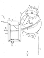
- Figs. 1 and 2 illustrate an apparatus for clearing trash from a furrow opener path.
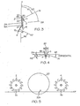
- Figs. 3 - 5 illustrate the orientation of the various parts.
- the trash clearing apparatus 1 is adapted for attachment to an implement for movement along the ground in an operating travel direction T ahead of a furrow opener, or a pair of furrow openers.
- the apparatus 1 is conventionally mounted to a seeding implement frame 40. Down pressure is applied to the apparatus 1 by conventional springs, hydraulic cylinders, or the like.
- the apparatus comprises a front finger wheel 2 rotatably mounted to the apparatus 1 and oriented to move trash from a first path P1 to a first side S1 of the apparatus 1.
- a rear finger wheel 4 is rotatably mounted to the apparatus 1 behind the front finger wheel 2 and is oriented to move trash from a second path P2 to an opposite second side S2 of the apparatus 1.
- the front and rear finger wheels 2, 4 are mounted such that bottom edges thereof 2b, 4b are located substantially on a horizontal plane HP and such that the first and second paths P1, P2 are closely adjacent.
- the bottom edges 2b, 4b are maintained substantially on the horizontal plane HP as the apparatus 1 moves up and down in response to terrain variations as it moves along the ground by the action of the parallel bar linkage 6.
- the rear bar 7 of the linkage 6 remains substantially vertical as the apparatus 1 moves up and down, and the operating parts of the apparatus 1 are attached thereto as described below.
- the separation along the operating travel direction between the front and rear finger wheels 2, 4 is such that a first trash stream TR1 thrown by the front finger wheel 2 does not meet a second trash stream TR2 thrown by the rear finger wheel 4 of an adjacent trash clearing apparatus.
- the separation should be 20 centimeters or more between rotational centers of the finger wheels 2, 4.
- a depth control wheel 8 is rotatably mounted to the bottom of an adjusting mechanism, shown in the embodiment as a screw jack 5, fixed to rear bar 7, such that it rolls along the ground 9 ahead of the rear finger wheel 4 on the first path P1 cleared by the front finger wheel 2.
- the vertical position of the depth control wheel 8 is adjustable relative to a vertical position of the horizontal plane HP by adjustment of screw jack 5.
- the handle of the screw jack 5 is conveniently located on the top side of the apparatus 1 so that adjustment may be made with reduced bending or crawling under the implement.
- the front finger wheel 2 is rotatably mounted to a front arm 10, fixed to the rear bar 7, about a first axis A1 oriented at a first angle N1 to the operating travel direction T such that a leading side 11 of the front finger wheel 2 is ahead of a trailing side 12 and at a first angle M1 from the horizontal such that the leading side 11 is below the trailing side 12 thereof whereby trash moved from the first path P1 by the front finger wheel 2 moves to a first side S1 of the apparatus 1.
- the rear finger wheel 2 is rotatably mounted to a rear arm 14, fixed to the rear bar 7, about a second axis A2 oriented at a second angle N2 to the operating travel direction T such that a leading side 15 of the rear finger wheel 4 is ahead of a trailing side 16, and at a second angle M2 from the horizontal such that the leading side 15 is below the trailing side 16 whereby trash moved from the second path P2 by the rear finger wheel 4 moves to the opposite second side S2 of the apparatus 1.
- the orientation of the axes A1, A2 is illustrated in Figs. 3 and 4 .
- the distance trash is thrown by the rear finger wheel 4 may be reduced by reducing the angle M2 of the second axis A2 to zero, or even tilting the axis A2 back the opposite way.
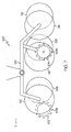
- the throwing distance can be varied so that trash stream TR2 thrown by the rear finger wheel 4, as indicated in Fig. 6 , does not land on the cleared path P1 of the adjacent apparatus.
- the trash stream TR1 thrown by the front finger wheel 2 is blocked by the disc 20, and so the throwing distance for this stream TR1 is not as critical as that for stream TR2 where there is nothing to block the stream.
- the finger wheel angles N1, N2, M1, and M2 can be adjusted for the particular conditions that are encountered.
- a furrow opening disc 20 is rotatably mounted to disc arm 19, fixed to rear bar 7, about a disc axis DA oriented at a disc angle N3 to the operating travel direction T such that a leading side 21 of the disc 20 corresponds to the leading side 11 of the front finger wheel 2.
- the disc angle N3 is sufficiently large to allow the disc 20 to open a furrow as is well known in the art.
- the disc 20 is located between the front and rear finger wheels 2, 4 such that a front edge 23 of the disc 20 is located ahead of a front edge 25 of the depth control wheel 8 and in proximity to the trailing side 12 of the front finger wheel 2 such that straws contacted by the disc 20 as it cuts into the ground 9 are at substantially the same time contacted by the front finger wheel 2, thereby placing tension on the straws and facilitating cutting of the straws by the disc 20.
- This orientation of a trash clearing finger wheel and furrow opening disc is known in the present art.
- the bottom edge 20b of the disc 20 is located at a fixed distance X below the horizontal plane HP, as illustrated in Fig. 5 .
- the distance X can be varied by mounting the furrow opening disc 20 in various holes 26 in disc arm 19, so that the furrow depth may be varied.
- the screw jack 5 is adjusted so that the horizontal plane HP is substantially at ground level, such that the finger wheels 2, 4 move trash but not soil.
- the furrow depth is set by adjusting the distance X with holes 26.
- the disc axis DA is horizontal in the illustrated embodiment, as seen in Fig. 4 .
- the disc axis DA could be at an angle to the horizontal such that the disc is inclined from the vertical as well as the operating travel direction, providing a double angled disc such as the BartonTM disc opener, manufactured by Flexicoil Ltd. of Saskatoon, Canada.
- the depth control wheel 8 is rotatably mounted about a wheel axis WA oriented substantially parallel to, and rearward of, the disc axis DA as seen in Fig. 3 .
- a front portion of the trailing side 28 of the depth control wheel 8 is closely adjacent to or touching a portion of the leading side 21 of the furrow opening disc 20 that is rearward of the front edge 23 of the furrow opening disc 20.
- the depth control wheel 8 runs along the ground 9 over soil moved by the leading side 21 and prevents soil throw. The depth control wheel 8 also cleans the furrow opening disc 20 as it comes out of the ground 9.
- the front edge 27 of the rear finger wheel 4 is located in proximity to the trailing side 22 of the disc 20.
- the paths P1, P2 are thus kept closely adjacent such that minimal trash is left between them.
- the apparatus may conveniently include a delivery tube 29 to deliver agricultural product to the furrow created by disc 20.
- the furrow can be conventionally closed if desired, or will be covered by following furrow openers in a paired row seeding implement.
- a paired row seeding implement 30 is schematically illustrated in Fig. 6 to show the action of the trash clearing apparatuses 1 in the field, and to illustrate a set up for a paired row seeder where depth control wheels or skids for the furrow openers of the seeder also run on the cleared paths P1, P2. Depth control is thus improved since the depth control wheels run on the ground and do not ride over trash.
- a plurality of right and left trash clearing apparatuses 1R, 1L, and a center apparatus 1C are mounted at the front of the implement 30.
- the front finger wheels 2 throw first trash stream TR1 from each first path towards a first side S1 of each paired furrow opener path P1, P2, relative to an operating travel direction T of the implement.
- the first side S1 is on the right
- the left apparatus 1L the first side S1 is on the left.
- the rear finger wheel 4 throws second trash stream TR2 from each second path P2 towards the opposite second side S2 and on top of the first trash thrown by the front finger wheel 2 of an adjacent apparatus 1.
- the implement is shown with right and left apparatuses 1R, 1L in order to balance side draft as is known in the art.
- the center apparatus IC is required in the center of the implement to make the transition over from throwing one way with the front finger wheel 2 to the other way.
- the furrow opening tool 33 follows the first path P1 and is located toward the first side S1 of the trash clearing apparatus 1 relative to the depth control wheel 32 such that the depth control wheel 32 rolls on or adjacent to the second path P2, between the furrow opening tools 33 of the first and second furrow openers 31, 34.
- the second furrow opener 34 is oriented the opposite way, so that the furrow opening tool 33 follows the second path P2 and is located toward the second side S2 of the trash clearing apparatus relative to the depth control wheel 32 such that the depth control wheel 32 rolls on or adjacent to the first path P2, between the furrow opening tools 33 of the first and second furrow openers 31, 34.
- the paired row furrow opening tools 33 are thus running on cleared ground at a furrow spacing FS of, for example 5 inches, and as well the depth control wheels 32 are also running, as is preferred, on cleared ground between the furrow opening tools 33. Spacing the apparatuses 1 at a spacing AS of 15 inches along the implement results in a 10 inch spacing between the adjacent paired seed rows.
- the effective seed row spacing is 7.5 inches, which is desired by some farmers to achieve their preferred plant density.
- seed could be placed through the furrow opening disc 20 and fertilizer through the furrow opening tools 33, to provide a 15 inch row spacing.
- the apparatus 1 also provides seed/fertilizer separation as required to prevent seed damage.
- FIG. 7 and 8 An alternate apparatus 100 of the invention is schematically illustrated in Figs. 7 and 8 .
- the bottom edges 102b, 104b of the front and rear finger wheels 102, 104 are maintained at a substantially constant vertical position relative to the ground as the apparatus 100 moves up and down in response to terrain variations as it moves along the ground by a first depth control wheel 106 mounted to the apparatus 100 in a fixed vertical position relative to the front finger wheel 102 such that the first depth control wheel 106 rolls along the ground ahead of the rear finger wheel 104 on the first path P1' cleared by the front finger wheel 102, and by a second depth control wheel 108 mounted to the apparatus 100 in a fixed vertical position relative to the rear finger wheel 104 such that the second depth control wheel 108 rolls along the ground beside the rear finger wheel 104 on the first path P1'.
- a first furrow opening tool, first disc 110, is mounted to the apparatus 100 adjacent to the first depth control wheel 106 and in fixed vertical relation thereto so as to follow the first path P1'
- a sccond furrow opening tool, second disc 112 is mounted to the apparatus 100 adjacent to the second depth control wheel 108 and in fixed vertical relation thereto so as to also follow the first path P1' at a lateral distance from the first disc 110.
- the depth control wheel 106, 108 run on opposite sides of the respective discs 110, 112 so that same may run on the cleared first path P1'.
- the depth of the furrows made by first and second discs 110, 112 would be by mounting in one of a plurality of holes, such as holes 26 in Fig. 1 .
- a third furrow opening tool, third disc 114 is mounted to the apparatus 100 adjacent to a third depth control wheel 116 and in fixed vertical relation thereto so as to follow the second path P2'.
- the third depth control wheel 116 rolls along the first or second path P1', P2' and controls the depth of the furrow made by the third disc 114.
- the depth control wheels 106, 108, 116 can be connected to a screw jack 5 such as illustrated in Fig. 1 to allow easy adjustment of the vertical position of the depth control wheels.
- a screw jack 5 such as illustrated in Fig. 1 to allow easy adjustment of the vertical position of the depth control wheels.
- One or more of the furrow opening tools could be hoes rather than discs.
- the finger wheels 102, 104, discs 110, 112, 114, and depth control wheels 106, 108, 116 are mounted to a walking beam 120 to allow the apparatus 100 to follow ground contours.
- Fig. 9 illustrates an alternate apparatus 200 of the invention where the rear finger wheel 104 of Fig. 7 is moved ahead to a position generally beside the first depth control wheel 106 and in fixed vertical relation thereto.
- First depth control wheel 106 then controls the vertical position of the front and rear finger wheels 102, 104.
- the vertical control is not as precise as that of the previously illustrated embodiments, however would provide satisfactory service in some conditions, such as on level ground.
- Second depth control wheel 108 would then adjust the depth of the second disc 112, rather than requiring a plurality of holes as in the apparatus 100 of Fig. 7 .
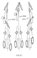
- Figs. 10 - 12 illustrate an alternative paired row seeding apparatus 300 of the invention.
- the trash clearing apparatus 301 is the same as that illustrated in Figs 1 and 2 , however in this embodiment, the parallel bar linkage 306 is attached to the implement frame 340 at the rear thereof instead at the front thereof as illustrated in Fig. 1 .
- the front bar 307 remains substantially vertical as the apparatus 301 moves up and down, thus maintaining the bottoms of the finger wheels 2, 4 on the horizontal plane HP.
- a paired row seeding apparatus 310 is mounted to a second parallel linkage 312 mounted to the implement frame 340 directly behind the trash clearing apparatus 301.
- Furrow opening tools illustrated as discs 314, are rotatably mounted to the second parallel linkage 312 and oriented so as to follow in the cleared paths P1, P2 provided by the trash clearing apparatus 301.
- a single furrow depth control device illustrated as furrow depth control wheel 316 is oriented to roll along the ground between the discs 314 and control the depth of both discs 314. The wheel 316 runs on the both paths P1 and P2 which are closely spaced so that very little trash is left on the ground between them.
- Spoked closing wheels 318 are conventionally mounted to close the furrows made by the discs 314, and seed or fertilizer is delivered to the furrows by tubes 320.
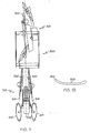
- FIG. 13 An alternate furrow depth control device is schematically illustrated in Fig. 13 as a skid plate 322 with a tumed up front end 324.
- the skid plate 322 follows the ground in the same manner as the wheel 316 and controls the depth of the furrow opening tools, such as discs 314.
- Fig. 12 schematically illustrates the arrangement of a plurality of the paired row seeding apparatuses 300 on an implement. Similar to the configuration of Fig. 6 , they include a right apparatus 300R, a left apparatus 300L, and a center apparatus 300C.
Abstract
Description
- This invention is in the field of agricultural seeding equipment, and in particular devices for clearing trash from the ground surface to permit effective working of the ground such as seeding, fertilizing, and the like.
- Tillage has been much reduced in modern agriculture in order to reduce costs, conserve moisture, and so forth. Seeding without tillage, or no-till seeding, has become common and preferred by many for crops such as grains, oilseeds, and pulses grown on the prairies of North America. These crops typically are grown in narrow rows, from 6 to 12 inches apart.
- Both disc and hoe type furrow openers are popular for no-till seeding as each have thcir own advantages. The performance of both disc and hoe types is best where crop residue such as straw and chaff, commonly referred to as trash, is light and evenly spread. Where trash is heavy, the disc may ride out of the ground. The discs can also push straws into the ground, a common problem called "hair-pinning". Hoe type openers often gather straw between them as they proceed along the field, causing plugging.
- Modern furrow openers also commonly include depth control wheels that maintain a constant depth of penetration into the soil, providing proper seed depth for optimum germination and growth. Heavy trash can interfere with proper operation of these depth control wheels, since ideally they should run on the ground, or over a thin, preferably consistent, layer of trash so that the proper depth is maintained. Where trash is thick and uneven, the depth control wheel rides up and over the trash, drawing the furrow opener out of the ground and reducing seed depth to less than optimum, often in fact leaving seed on top of the ground.
- Prior art has been addressed to devices for clearing trash from the path of a furrow opener to improve performance.
United States Patent Numbers 4,785,890 to Martin,5,346,020 to Bassett,5,497,836 to Groff, and5,878,678 to Stephens et al. disclose trash clearing apparatuses that include a pair of spoked or toothed trash clearing finger wheels in a V orientation in front of a furrow opener, such that the centers of the finger wheels are substantially located on a line parallel to the operating travel direction. The finger wheels clear trash in each direction from in front of the opener. Where such V oriented finger wheels are used in a narrow row spacing, with the furrow openers close together, the trash thrown away from the path by one of the finger wheels of the V apparatus is thrown against trash being thrown the opposite way by the opposite finger wheels of the adjacent V apparatus. The trash is thus not thrown clear since the two streams of trash meet. -
United States Patent Number 5,970,892 to Wendling et al. shows a single similar wheel, essentially one half of the V apparatus of the '678 patent to Stephens et al. The single wheel clears sufficient area to improve the performance of the disc. The clearing wheel is oriented to throw trash to the side of the row opposite the depth control wheel, and does not therefore clear trash from the path of the depth control wheel. -
US patent 5,341,754 discloses a rotary row cleaner including a pair of toothed wheels oriented to throw trash from adjacent paths. No control mechanism is provided to allow narrow row spacings. - Trash clearing finger wheels are well known in a variety types, as disclosed for example in
United States Patent Numbers 5,346,020 to Bassett,5,497,836 to Groff, and5,878,678 to Stephens et al. - These finger wheel clearing apparatuses should be maintained in proper relation to the ground without entering the ground and thereby increasing draft and stress on the apparatus, as well as causing excessive soil to be thrown with the trash.
- It is the object of the present invention to provide an improved apparatus as claimed in
claim 1 for clearing trash from a furrow opener path that is suitable for narrow row spacings. It is further object of the invention to provide such an apparatus that can incorporate a furrow opening disc for applying agricultural product. - It is a further object of the invention to provide a paired row seeding implement as claimed in
claim 11 where such a trash clearing apparatus clears trash from the path of two furrow openers. - It is a further object of the invention to provide an improved method of clearing trash as claimed in
claim 15 suitable for use with narrow row spacings. - The invention provides, in one aspect, an apparatus for clearing trash from a furrow opener path, the trash clearing apparatus adapted for attachment to an implement for movement along the ground in an operating travel direction ahead of a furrow opener. The apparatus comprises a front finger wheel rotatably mounted to the apparatus and oriented to move trash from a first path to a first side of the apparatus and a rear finger wheel rotatably mounted to the apparatus behind the front finger wheel and oriented to move trash from a sccond path to an opposite second side of the apparatus. The front and rear finger wheels are mounted such that the first and second paths are adjacent to each other, and such that the separation along the operating travel direction between the front and rear finger wheels is such that a first trash stream thrown by the front finger wheel does not meet a second trash stream thrown by the rear finger wheel of an adjacent trash clearing apparatus. A depth control wheel is rotatably mounted to the apparatus such that the depth control wheel rolls along the ground on the first path cleared by the front finger wheel. The depth control wheel is operative to maintain bottom edges of the front and rear finger wheels at a substantially constant vertical position relative to the ground. An adjusting mechanism is opcrative to adjust a vertical position of the depth control wheel with respect to at least one of the front and rear finger wheels.
- The front finger wheel is typically rotatably mounted to the apparatus about a first axis, the first axis oriented at a first angle to the operating travel direction such that a leading side of the front finger wheel is ahead of a trailing side, and at a first angle from the horizontal such that the leading side is below the trailing side thereof whereby trash moved from a first path by the front finger wheel moves to a first side of the apparatus. Similarly the rear finger wheel is typically rotatably mounted to the apparatus behind the front finger wheel about a second axis, the second axis oriented at a second angle to the operating travel direction such that a leading side of the rear finger wheel is ahead of a trailing side, and at a second angle from the horizontal such that the leading side is below the trailing side thereof whereby trash moved from a second path by the rear finger wheel moves to an opposite second side of the apparatus.
- In a second aspect the invention provides A paired row seeding implement attachable to a towing vehicle for movement along the ground in an operating travel direction, the implement comprising: a trash clearing apparatus attached to the implement, the apparatus comprising a front finger wheel rotatably mounted to the and oriented to move trash from a first path to a first side of the apparatus, a rear finger wheel rotatably mounted to the apparatus behind the front finger wheel and oriented to move trash from a second path to an opposite second side of the apparatus, wherein the front and rear finger wheels are mounted such that the first and second paths are adjacent to each other and such that the separation along the operating travel direction between the front and rear finger wheels is such that a first trash stream thrown by the front finger wheel does not meet a second trash stream thrown by the rear finger wheel of an adjacent trash clearing apparatus, a depth control wheel rotatably mounted to the apparatus such that the depth control wheel rolls along the ground on the first path cleared by the front finger wheel, the depth control wheel operative to maintain bottom edges of the front and rear finger wheels at a substantially constant vertical position relative to the ground by; and an adjusting mechanism operative to adjust a vertical position of the depth control wheel with respect to at least one of the front and rear finger wheels. A first furrow opening tool is attached to the implement behind the trash clearing apparatus and oriented to follow the first path, and a second furrow opening tool is attached to the implement behind the trash clearing apparatus and oriented to follow the second path. A furrow depth control device mounted at a fixed vertical position relative to at least one furrow opening tool, and oriented to move along the ground between the first and second furrow opening tools and maintain the first and second furrow opening tools at a substantially constant vertical position with respect to the ground.
- The apparatus clears two closely adjacent paths, with little trash left between the paths. A furrow opening implement can incorporate a following furrow opener in each path, with a depth control wheel running on the cleared ground of the paths. One depth control device, such as a wheel or skid plate can control the depth of two adjacent openers.
- The invention also provides, in a third aspect, a method of clearing trash from a plurality of adjacent paired furrow opener paths of a furrow opening implement, each paired furrow opener path comprising a first path and an adjacent second path. The method comprises with a first front finger wheel, throwing first trash from the first path towards a first side of the paired furrow opener path, relative to an operating travel direction of the implement; after the first trash has substantially landed on the ground, with a rear finger wheel throwing second trash from the second path towards a second side of the paired furrow opener path, relative to the operating travel direction of the implement, and on top of first trash thrown by an adjacent second front finger wheel; maintaining bottom edges of the front and rear finger wheels at a substantially constant vertical position relative to the ground with a depth control wheel oriented to roll along the ground on the first path cleared by the front finger wheel.
- The front finger wheel moves trash to one side, and the rear finger wheel moves adjacent trash to the opposite side. In a narrow row spacing, a plurality of front finger wheels moves first trash from a first path in one direction, while the following plurality of rear finger wheels moves second trash in the opposite direction. The first trash has landed on the ground by the time the second trash is moved so that the second trash lands on top of the first trash. Conventionally, the trash is moved both directions at once by a V oriented pair of finger wheels such that the trash moving in one direction hits the trash moving in the opposite direction, resulting in a poor spread, and spill back onto the cleared path.
- The bottom edges of the front and rear finger wheels may be maintained at a substantially constant vertical position relative to the ground by one depth control wheel rolling along the ground on the first path cleared by the front finger wheel, and beside or somewhat ahead of the rear finger wheel. The depth control wheel runs on cleared ground of the first path and so maintains the proper relation of the apparatus with the ground, as it does not ride up and down over trash accumulations. Depending on the attachment to the implement, as the apparatus moves along the ground the front and rear finger wheels may move somewhat relative to the ground, however such a system will often provide satisfactory service.
- More precise vertical positioning of the front and rear finger wheels may be provided. The front and rear finger wheels may be oriented such that bottom edges thereof are on a horizontal plane as they move up and down with the terrain and a depth control wheel is located between them in a good location to maintain the finger wheels at the proper vertical location relative to the ground.
- Alternatively a depth control wheel may be provided adjacent to each finger wheel to control the vertical position thereof. Both depth control wheels run on the cleared ground of the first path, and so are not moving up and down over uncleared trash.
- More precise control of the vertical position of the finger wheels reduces excessive stress and soil throw.
- The addition of a furrow opening disc closely behind the front finger wheel provides the advantage, well known in the art, of cutting straws that are held under tension by the finger wheel as it pulls the trash away from the path of the furrow opening disc. Agricultural product such as seed or fertilizer can also be placed in the soil.
- While the invention is claimed in the concluding portions hereof, preferred embodiments are provided in the accompanying detailed description which may be best understood in conjunction with the accompanying diagrams where like parts in each of the several diagrams are labeled with like numbers, and where:
-
Fig. 1 is a side view of an embodiment of the invention; -
Fig. 2 is a top view of the embodiment ofFig. 1 ; -
Fig. 3 is a schematic top view of the embodiment ofFig. 1 showing the orientation of the axes of the rotating parts relative to the operating travel direction; -
Fig. 4 is a schematic rear view of the embodiment ofFig. 1 showing the orientation of the axes of the rotating parts relative to the horizontal; -
Fig. 5 is a schematic side view showing the vertical relationship of the front and rear finger wheels, and furrow opening disc; -
Fig. 6 is a schematic top view of a paired row seeding implement using the embodiment ofFig. 1 to clear trash from a pair of furrow opening tools; -
Fig. 7 is a schematic side view of an alternate embodiment where the vertical position of the finger wheels is maintained by a depth control wheel on each finger wheel; -
Fig. 8 is a schematic top view of the embodiment ofFig. 7 ; -
Fig. 9 is a schematic side view of an alternate embodiment where the vertical position of the finger wheels is maintained by a single depth control wheel running between the finger wheels; -
Fig. 10 is a side view of an alternate paired row seeding apparatus of the invention; -
Fig. 11 is top view of the apparatus ofFig. 10 ; -
Fig. 12 is a schematic top view of a typical arrangement of a plurality of the pairedrow seeding apparatuses 300 on an implement; -
Fig. 13 is a side view of a skid plate that can be used as a furrow depth control device. -
Figs. 1 and2 illustrate an apparatus for clearing trash from a furrow opener path.Figs. 3 - 5 illustrate the orientation of the various parts. Thetrash clearing apparatus 1 is adapted for attachment to an implement for movement along the ground in an operating travel direction T ahead of a furrow opener, or a pair of furrow openers. Theapparatus 1 is conventionally mounted to a seeding implementframe 40. Down pressure is applied to theapparatus 1 by conventional springs, hydraulic cylinders, or the like. - The apparatus comprises a
front finger wheel 2 rotatably mounted to theapparatus 1 and oriented to move trash from a first path P1 to a first side S1 of theapparatus 1. Arear finger wheel 4 is rotatably mounted to theapparatus 1 behind thefront finger wheel 2 and is oriented to move trash from a second path P2 to an opposite second side S2 of theapparatus 1. In the embodiments ofFigs. 1 and2 the front andrear finger wheels bottom edges thereof 2b, 4b are located substantially on a horizontal plane HP and such that the first and second paths P1, P2 are closely adjacent. Thebottom edges 2b, 4b are maintained substantially on the horizontal plane HP as theapparatus 1 moves up and down in response to terrain variations as it moves along the ground by the action of theparallel bar linkage 6. The rear bar 7 of thelinkage 6 remains substantially vertical as theapparatus 1 moves up and down, and the operating parts of theapparatus 1 are attached thereto as described below. - As illustrated in
Fig. 6 , the separation along the operating travel direction between the front andrear finger wheels front finger wheel 2 does not meet a second trash stream TR2 thrown by therear finger wheel 4 of an adjacent trash clearing apparatus. For common implement travel speeds, it is contemplated that the separation should be 20 centimeters or more between rotational centers of thefinger wheels - A
depth control wheel 8 is rotatably mounted to the bottom of an adjusting mechanism, shown in the embodiment as a screw jack 5, fixed to rear bar 7, such that it rolls along theground 9 ahead of therear finger wheel 4 on the first path P1 cleared by thefront finger wheel 2. The vertical position of thedepth control wheel 8 is adjustable relative to a vertical position of the horizontal plane HP by adjustment of screw jack 5. The handle of the screw jack 5 is conveniently located on the top side of theapparatus 1 so that adjustment may be made with reduced bending or crawling under the implement. - The
front finger wheel 2 is rotatably mounted to afront arm 10, fixed to the rear bar 7, about a first axis A1 oriented at a first angle N1 to the operating travel direction T such that a leadingside 11 of thefront finger wheel 2 is ahead of a trailingside 12 and at a first angle M1 from the horizontal such that the leadingside 11 is below the trailingside 12 thereof whereby trash moved from the first path P1 by thefront finger wheel 2 moves to a first side S1 of theapparatus 1. - Similarly the
rear finger wheel 2 is rotatably mounted to arear arm 14, fixed to the rear bar 7, about a second axis A2 oriented at a second angle N2 to the operating travel direction T such that a leadingside 15 of therear finger wheel 4 is ahead of a trailingside 16, and at a second angle M2 from the horizontal such that the leadingside 15 is below the trailingside 16 whereby trash moved from the second path P2 by therear finger wheel 4 moves to the opposite second side S2 of theapparatus 1. The orientation of the axes A1, A2 is illustrated inFigs. 3 and 4 . - The distance trash is thrown by the
rear finger wheel 4 may be reduced by reducing the angle M2 of the second axis A2 to zero, or even tilting the axis A2 back the opposite way. The throwing distance can be varied so that trash stream TR2 thrown by therear finger wheel 4, as indicated inFig. 6 , does not land on the cleared path P1 of the adjacent apparatus. The trash stream TR1 thrown by thefront finger wheel 2 is blocked by thedisc 20, and so the throwing distance for this stream TR1 is not as critical as that for stream TR2 where there is nothing to block the stream. The finger wheel angles N1, N2, M1, and M2 can be adjusted for the particular conditions that are encountered. - A
furrow opening disc 20 is rotatably mounted to disc arm 19, fixed to rear bar 7, about a disc axis DA oriented at a disc angle N3 to the operating travel direction T such that a leadingside 21 of thedisc 20 corresponds to the leadingside 11 of thefront finger wheel 2. The disc angle N3 is sufficiently large to allow thedisc 20 to open a furrow as is well known in the art. Thedisc 20 is located between the front andrear finger wheels front edge 23 of thedisc 20 is located ahead of afront edge 25 of thedepth control wheel 8 and in proximity to the trailingside 12 of thefront finger wheel 2 such that straws contacted by thedisc 20 as it cuts into theground 9 are at substantially the same time contacted by thefront finger wheel 2, thereby placing tension on the straws and facilitating cutting of the straws by thedisc 20. This orientation of a trash clearing finger wheel and furrow opening disc is known in the present art. - The
bottom edge 20b of thedisc 20 is located at a fixed distance X below the horizontal plane HP, as illustrated inFig. 5 . The distance X can be varied by mounting thefurrow opening disc 20 invarious holes 26 in disc arm 19, so that the furrow depth may be varied. The screw jack 5 is adjusted so that the horizontal plane HP is substantially at ground level, such that thefinger wheels - As is common in the field, the disc axis DA is horizontal in the illustrated embodiment, as seen in
Fig. 4 . Alternately, it is contemplated that the disc axis DA could be at an angle to the horizontal such that the disc is inclined from the vertical as well as the operating travel direction, providing a double angled disc such as the Barton™ disc opener, manufactured by Flexicoil Ltd. of Saskatoon, Canada. - The
depth control wheel 8 is rotatably mounted about a wheel axis WA oriented substantially parallel to, and rearward of, the disc axis DA as seen inFig. 3 . A front portion of the trailingside 28 of thedepth control wheel 8 is closely adjacent to or touching a portion of the leadingside 21 of thefurrow opening disc 20 that is rearward of thefront edge 23 of thefurrow opening disc 20. Thedepth control wheel 8 runs along theground 9 over soil moved by the leadingside 21 and prevents soil throw. Thedepth control wheel 8 also cleans thefurrow opening disc 20 as it comes out of theground 9. - The
front edge 27 of therear finger wheel 4 is located in proximity to the trailingside 22 of thedisc 20. The paths P1, P2 are thus kept closely adjacent such that minimal trash is left between them. - The apparatus may conveniently include a
delivery tube 29 to deliver agricultural product to the furrow created bydisc 20. The furrow can be conventionally closed if desired, or will be covered by following furrow openers in a paired row seeding implement. - A paired row seeding implement 30 is schematically illustrated in
Fig. 6 to show the action of thetrash clearing apparatuses 1 in the field, and to illustrate a set up for a paired row seeder where depth control wheels or skids for the furrow openers of the seeder also run on the cleared paths P1, P2. Depth control is thus improved since the depth control wheels run on the ground and do not ride over trash. - A plurality of right and left
trash clearing apparatuses center apparatus 1C are mounted at the front of the implement 30. Thefront finger wheels 2 throw first trash stream TR1 from each first path towards a first side S1 of each paired furrow opener path P1, P2, relative to an operating travel direction T of the implement. For theright apparatus 1R, the first side S1 is on the right, and for theleft apparatus 1L, the first side S1 is on the left. - After the first trash has landed on the ground, the
rear finger wheel 4 throws second trash stream TR2 from each second path P2 towards the opposite second side S2 and on top of the first trash thrown by thefront finger wheel 2 of anadjacent apparatus 1. - Thus it can be seen that trash flows smoothly as the implement passes. With prior art trash clearing apparatuses the
finger wheels - The implement is shown with right and left
apparatuses front finger wheel 2 to the other way. - A
first furrow opener 31, including adepth control wheel 32 and afurrow opening tool 33 which as illustrated is a disc but could also be a hoc opener. Thefurrow opening tool 33 follows the first path P1 and is located toward the first side S1 of thetrash clearing apparatus 1 relative to thedepth control wheel 32 such that thedepth control wheel 32 rolls on or adjacent to the second path P2, between thefurrow opening tools 33 of the first andsecond furrow openers - The
second furrow opener 34 is oriented the opposite way, so that thefurrow opening tool 33 follows the second path P2 and is located toward the second side S2 of the trash clearing apparatus relative to thedepth control wheel 32 such that thedepth control wheel 32 rolls on or adjacent to the first path P2, between thefurrow opening tools 33 of the first andsecond furrow openers - The paired row
furrow opening tools 33 are thus running on cleared ground at a furrow spacing FS of, for example 5 inches, and as well thedepth control wheels 32 are also running, as is preferred, on cleared ground between thefurrow opening tools 33. Spacing theapparatuses 1 at a spacing AS of 15 inches along the implement results in a 10 inch spacing between the adjacent paired seed rows. The effective seed row spacing is 7.5 inches, which is desired by some farmers to achieve their preferred plant density. Alternatively seed could be placed through thefurrow opening disc 20 and fertilizer through thefurrow opening tools 33, to provide a 15 inch row spacing. Theapparatus 1 also provides seed/fertilizer separation as required to prevent seed damage. - With the
apparatus 1 and furrow openingtools 33 mounted separately on the implement 30, each rides separately over obstacles in the field, such as stones. - An
alternate apparatus 100 of the invention is schematically illustrated inFigs. 7 and8 . Thebottom edges rear finger wheels apparatus 100 moves up and down in response to terrain variations as it moves along the ground by a firstdepth control wheel 106 mounted to theapparatus 100 in a fixed vertical position relative to thefront finger wheel 102 such that the firstdepth control wheel 106 rolls along the ground ahead of therear finger wheel 104 on the first path P1' cleared by thefront finger wheel 102, and by a seconddepth control wheel 108 mounted to theapparatus 100 in a fixed vertical position relative to therear finger wheel 104 such that the seconddepth control wheel 108 rolls along the ground beside therear finger wheel 104 on the first path P1'. - A first furrow opening tool,
first disc 110, is mounted to theapparatus 100 adjacent to the firstdepth control wheel 106 and in fixed vertical relation thereto so as to follow the first path P1', and a sccond furrow opening tool,second disc 112 is mounted to theapparatus 100 adjacent to the seconddepth control wheel 108 and in fixed vertical relation thereto so as to also follow the first path P1' at a lateral distance from thefirst disc 110. Thedepth control wheel respective discs second discs holes 26 inFig. 1 . - A third furrow opening tool,
third disc 114, is mounted to theapparatus 100 adjacent to a thirddepth control wheel 116 and in fixed vertical relation thereto so as to follow the second path P2'. The thirddepth control wheel 116 rolls along the first or second path P1', P2' and controls the depth of the furrow made by thethird disc 114. - The
depth control wheels Fig. 1 to allow easy adjustment of the vertical position of the depth control wheels. One or more of the furrow opening tools could be hoes rather than discs. - The
finger wheels discs depth control wheels walking beam 120 to allow theapparatus 100 to follow ground contours. -
Fig. 9 illustrates analternate apparatus 200 of the invention where therear finger wheel 104 ofFig. 7 is moved ahead to a position generally beside the firstdepth control wheel 106 and in fixed vertical relation thereto. Firstdepth control wheel 106 then controls the vertical position of the front andrear finger wheels depth control wheel 108 would then adjust the depth of thesecond disc 112, rather than requiring a plurality of holes as in theapparatus 100 ofFig. 7 . -
Figs. 10 - 12 illustrate an alternative pairedrow seeding apparatus 300 of the invention. Thetrash clearing apparatus 301 is the same as that illustrated inFigs 1 and2 , however in this embodiment, theparallel bar linkage 306 is attached to the implementframe 340 at the rear thereof instead at the front thereof as illustrated inFig. 1 . Thefront bar 307 remains substantially vertical as theapparatus 301 moves up and down, thus maintaining the bottoms of thefinger wheels - A paired
row seeding apparatus 310 is mounted to a secondparallel linkage 312 mounted to the implementframe 340 directly behind thetrash clearing apparatus 301. Furrow opening tools, illustrated asdiscs 314, are rotatably mounted to the secondparallel linkage 312 and oriented so as to follow in the cleared paths P1, P2 provided by thetrash clearing apparatus 301. A single furrow depth control device, illustrated as furrowdepth control wheel 316 is oriented to roll along the ground between thediscs 314 and control the depth of bothdiscs 314. Thewheel 316 runs on the both paths P1 and P2 which are closely spaced so that very little trash is left on the ground between them.Spoked closing wheels 318 are conventionally mounted to close the furrows made by thediscs 314, and seed or fertilizer is delivered to the furrows bytubes 320. - An alternate furrow depth control device is schematically illustrated in
Fig. 13 as askid plate 322 with a tumed upfront end 324. Theskid plate 322 follows the ground in the same manner as thewheel 316 and controls the depth of the furrow opening tools, such asdiscs 314. -
Fig. 12 schematically illustrates the arrangement of a plurality of the pairedrow seeding apparatuses 300 on an implement. Similar to the configuration ofFig. 6 , they include aright apparatus 300R, aleft apparatus 300L, and a center apparatus 300C. - The foregoing is considered as illustrative only of the principles of the invention. Further, since numerous changes and modifications will readily occur to those skilled in the art, it is not desired to limit the invention to the exact construction and operation shown and described, and accordingly, all such suitable changes or modifications in structure or operation which may be resorted to are intended to fall within the scope of the claimed invention as limited by the claims.
Claims (15)
- A trash clearing apparatus for clearing trash from a furrow opener path, adapted for attachment to an implement for movement along the ground in an operating travel direction (T) ahead of a furrow opener, the apparatus (1) comprising:a front finger wheel (2) rotatably mounted to the apparatus and oriented to move trash from a first path (P1) to a first side (S1) of the apparatus;a rear finger wheel (4) rotatably mounted to the apparatus behind the front finger wheel (2) and oriented to move trash from a second path (P2) to an opposite second side (S2) of the apparatus;the front and rear finger wheels (2, 4) being mounted such that the first and second paths are adjacent to each other;and the separation along the operating travel direction between the front and rear finger wheels (2, 4) being such that a first trash stream (TR1) thrown by the front finger wheel (2) does not meet a second trash stream (TR2) thrown by the rear finger wheel (4) of an adjacent trash clearing apparatus;characterized in thata depth control wheel (8) is rotatably mounted to the apparatus such that the depth control wheel rolls along the ground (9) on the first patch (P1) cleared by the front finger wheel (2), the depth control wheel being operative to maintain bottom edges (2b, 4b) of the front and rear finger wheels (2, 4) at a substantially constant vertical position relative to the ground; andan adjusting mechanism (5) is operative to adjust a vertical position of the depth control wheel (8) with respect to at least one of the front and rear finger wheels (2, 4).
- The apparatus of Claim 1 wherein the front finger wheel (2), rear finger wheel (4), and adjusting mechanism (5) are fixed to a rigid member (7).
- The apparatus of any one of Claims 1 or 2 wherein the bottom edges (2b, 4b) of the front and rear finger wheels (2, 4) are maintained at a substantially constant vertical position relative to the ground as the apparatus moves along the ground by maintaining the bottom edges of the front and rear finger wheels on a substantially horizontal plane (HP), and wherein the depth control wheel (8) maintains a vertical position of the horizontal plane (HP), substantially constant relative to the ground as the apparatus moves along the ground.
- The apparatus of Claim 3 wherein the bottom edges (2b, 4b) of the front and rear finger wheels (2, 4) are maintained on the substantially horizontal (HP) plane by attachment to a parallel bar linkage (6).
- The apparatus of any one of Claims 1 or 2 wherein the means to maintain bottom edges (102b, 104b) of the front and rear finger wheels (102, 104) at a substantially constant vertical position relative to the ground as the apparatus (100) moves along the ground comprises:a front depth control wheel (106) mounted to the apparatus in a fixed vertical position relative to the front finger wheel (102) such that the front depth control wheel (106) rolls along the ground ahead of the rear finger wheel (104) on the first path (P1'),a front adjusting mechanism operative to adjust the vertical position of the front depth control wheel (106) with respect to at the front finger wheel (102);a rear depth control wheel (108) mounted to the apparatus (100) in a fixed vertical position relative to the rear finger wheel (104) such that the rear depth control wheel rolls along the ground beside the rear finger wheel (104) on the first path (P1'); anda rear adjusting mechanism operative to adjust the vertical position of the rear depth control wheel (108) with respect to the rear finger wheel (104).
- The apparatus of any one of Claims 1 - 5 further comprising a furrow opening disc (33) rotatably mounted between the front and rear finger wheels (2,4).
- The apparatus of Claim 5 further comprising a first furrow opening tool (110) mounted to the apparatus (100) adjacent to the front depth control wheel (106) and in fixed vertical relation thereto so as to follow the first path (P1'), and a second furrow opening tool (112) mounted to the apparatus (100) adjacent to the rear depth control wheel (108) and in fixed vertical relation thereto so as to follow the first path (P1') at a lateral distance from the first furrow opening tool (110).
- The apparatus of Claim 7 further comprising a third furrow opening tool (114) mounted to the apparatus (100) adjacent to a third depth control wheel (116) and in fixed vertical relation thereto so as to follow the second path (P2'), the third depth control wheel (116) rolling along the first or second path (P1', P2').
- The apparatus of one of Claims 1 - 8 wherein the adjusting mechanism (5) is operated by a control located on a top side of the apparatus (1, 100).
- The apparatus of one of Claims 1 - 12 wherein in a center of the rear finger wheel is at least 20 centimeters behind a center of the front finger wheel.
- A paired row seeding implement attachable to a towing vehicle for movement along the ground in an operating travel direction, the implement (300) comprising a trash clearing apparatus according to Claim 1 attached to the implement.
- The implement of Claim 11 wherein the furrow depth control comprises a first depth control wheel (106) mounted at a fixed vertical position relative to the first furrow opening tool (110) and oriented to roll along the ground between the first and second furrow opening tools (110, 112), and a second depth control wheel (108) mounted at a fixed vertical position relative to the second furrow opening tool (112) and oriented to roll along the ground between the first and second furrow opening tools (110, 112).
- The implement of Claim 11 wherein the trash clearing apparatus (301) is mounted on a front parallel bar linkage (307) attached to the implement (300), and wherein the first furrow opening tool (314), second furrow opening tool (314), and the depth control device (316) are mounted on a second bar parallel linkage (312) attached to the implement behind the front parallel bar linkage (307).
- The apparatus of one of Claims 11 - 13 wherein a center of the rear finger wheel (104) is at least 20 centimeters behind a center of the front finger wheel (102).
- A method of clearing trash from a plurality of adjacent paired furrow opener paths (300L, 300G, 300R) of a furrow opening implement, each paired furrow opener path comprising a first path and an adjacent second path, the method comprising:with a first front finger wheel, throwing first trash from the first path towards a first side of the paired furrow opener path, relative to an operating travel direction of the implement;after the first trash has substantially landed on the ground, with a rear finger wheel throwing second trash from the second path towards a second side of the paired furrow opener path, relative to the operating travel direction of the implement, and generally on top of first trash thrown by and adjacent second front finger wheel;characterized in that it consists ofmaintaining bottom edges of the front and rear finger wheels (102, 104) at a substantially constant vertical position relative to the ground with a depth control wheel (31 b) oriented to roll along the ground on the first path (P1) cleared by the front finger wheel.
Applications Claiming Priority (2)
| Application Number | Priority Date | Filing Date | Title |
|---|---|---|---|
| CA002329396A CA2329396A1 (en) | 2000-12-21 | 2000-12-21 | Apparatus and method for clearing trash from furrow opener path |
| CA2329396 | 2000-12-21 |
Publications (2)
| Publication Number | Publication Date |
|---|---|
| EP1216608A1 EP1216608A1 (en) | 2002-06-26 |
| EP1216608B1 true EP1216608B1 (en) | 2010-08-11 |
Family
ID=4167977
Family Applications (1)
| Application Number | Title | Priority Date | Filing Date |
|---|---|---|---|
| EP01403310A Expired - Lifetime EP1216608B1 (en) | 2000-12-21 | 2001-12-20 | Apparatus and method for clearing trash from furrow opener path |
Country Status (6)
| Country | Link |
|---|---|
| US (1) | US6575104B2 (en) |
| EP (1) | EP1216608B1 (en) |
| AT (1) | ATE476866T1 (en) |
| AU (1) | AU780849B2 (en) |
| CA (1) | CA2329396A1 (en) |
| DE (1) | DE60142769D1 (en) |
Families Citing this family (64)
| Publication number | Priority date | Publication date | Assignee | Title |
|---|---|---|---|---|
| US6644224B1 (en) * | 1993-06-08 | 2003-11-11 | Dawn Equipment Company | Apparatus for preparing soil for the placement of seed and additive |
| US7451712B2 (en) * | 2004-05-12 | 2008-11-18 | Dawn Equipment Company | Agricultural tillage device |
| US8359988B2 (en) | 2007-07-24 | 2013-01-29 | Dawn Equipment Company | Agricultural tillage device |
| US7743718B2 (en) * | 2007-07-24 | 2010-06-29 | Dawn Equipment Company | Agricultural tillage device |
| US8356563B2 (en) * | 2007-12-21 | 2013-01-22 | Schaffert Paul E | Seed planter with equalizer assembly |
| US9204590B2 (en) * | 2008-12-22 | 2015-12-08 | Schaffert Manufacturing Company, Inc. | Seed planter with equalizer assembly |
| US9232689B2 (en) | 2007-12-21 | 2016-01-12 | Schaffert Manufacturing Company, Inc. | Seed planter with equalizer assembly |
| US10830274B2 (en) * | 2007-12-21 | 2020-11-10 | Schaffert Manufacturing Company, Inc. | Seed planter with equalizer assembly |
| US8047301B2 (en) * | 2008-10-17 | 2011-11-01 | Cnh Canada, Ltd. | Disc gang assembly for an agricultural implement |
| US7673570B1 (en) | 2008-12-01 | 2010-03-09 | Dawn Equipment Company | Row-clearing unit for agricultural implement |
| US8430179B2 (en) * | 2009-04-30 | 2013-04-30 | L & B Manufacturing, Inc. | Soil tilling and planting implement |
| US8327780B2 (en) | 2009-10-16 | 2012-12-11 | Dawn Equipment Company | Agricultural implement having fluid delivery features |
| US8393407B2 (en) | 2010-04-12 | 2013-03-12 | Brian E. Freed | Crop residue clearing device |
| US9226440B2 (en) | 2010-09-15 | 2016-01-05 | Dawn Equipment Company | Agricultural apparatus with hydraulic cylinder and manifold for a row unit |
| US9107337B2 (en) | 2012-08-20 | 2015-08-18 | Dawn Equipment Company | Agricultural apparatus for sensing and providing feedback of soil property changes in real time |
| US8985232B2 (en) | 2012-08-20 | 2015-03-24 | Dawn Equipment Company | Agricultural apparatus for sensing and providing feedback of soil property changes in real time |
| US8544397B2 (en) | 2010-09-15 | 2013-10-01 | Dawn Equipment Company | Row unit for agricultural implement |
| US8544398B2 (en) | 2010-09-15 | 2013-10-01 | Dawn Equipment Company | Hydraulic down pressure control system for closing wheels of an agricultural implement |
| US9107338B2 (en) | 2010-09-15 | 2015-08-18 | Dawn Equipment Company | Agricultural systems |
| US8776702B2 (en) | 2010-09-15 | 2014-07-15 | Dawn Equipment Company | Hydraulic down pressure control system for an agricultural implement |
| US9232687B2 (en) | 2010-09-15 | 2016-01-12 | Dawn Equipment Company | Agricultural systems |
| US9055712B2 (en) | 2010-09-15 | 2015-06-16 | Dawn Equipment Company | Agricultural apparatus with integrated controller for a row unit |
| US8763713B2 (en) | 2012-01-27 | 2014-07-01 | Dawn Equipment Company | Agricultural implement with automatic down pressure control |
| US9326438B2 (en) | 2010-12-21 | 2016-05-03 | Schaffert Manufacturing Company, Inc. | Trash deflector |
| US8863857B2 (en) | 2011-02-23 | 2014-10-21 | Dawn Equipment Company | Row unit for agricultural implement |
| US9271437B2 (en) | 2011-07-01 | 2016-03-01 | Charles H. Martin | Agricultural field preparation device |
| UA110988C2 (en) | 2011-08-05 | 2016-03-10 | Пресіжн Плентінг Елелсі | Apparatus, systems and methods for controlling the downforce of an agricultural implement having multiple row units |
| US8636077B2 (en) | 2012-05-22 | 2014-01-28 | Dawn Equipment Company | Agricultural tool with structural housing for hydraulic actuator |
| US9307690B2 (en) | 2012-06-14 | 2016-04-12 | Dawn Equipment Company | Forged toothed wheel for a row crop planter |
| US8910581B2 (en) | 2012-07-25 | 2014-12-16 | Dawn Equipment Company | Side dressing fertilizer coulter |
| UA117811C2 (en) | 2012-07-25 | 2018-10-10 | Пресіжн Плентінг Елелсі | Integrated implement downforce control systems, methods, and apparatus |
| US9192091B2 (en) | 2013-02-01 | 2015-11-24 | Dawn Equipment Company | Agricultural apparatus with hybrid single-disk, double-disk coulter arrangement |
| US9215838B2 (en) | 2013-02-01 | 2015-12-22 | Dawn Equipment Company | Agricultural apparatus with hybrid single-disk, double-disk coulter arrangement |
| US9693497B2 (en) | 2013-03-14 | 2017-07-04 | Schaffert Manufacturing Company, Inc. | Mounting bracket for agricultural row unit |
| US9137939B2 (en) | 2013-03-15 | 2015-09-22 | Alan E. Winick | Electric adjusting apparatus for row cleaners |
| US9456542B2 (en) | 2013-03-15 | 2016-10-04 | Schaffert Manufacturing Company, Inc. | Debris assembly for an agricultural row unit |
| CA2925735C (en) * | 2013-11-12 | 2020-03-10 | C.S. Gent & Sons Ltd. | Soil opening |
| US9668398B2 (en) | 2014-02-05 | 2017-06-06 | Dawn Equipment Company | Agricultural system for field preparation |
| US9241438B2 (en) | 2014-02-05 | 2016-01-26 | Dawn Equipment Company | Agricultural system for field preparation |
| US10721855B2 (en) | 2014-02-05 | 2020-07-28 | Dawn Equipment Company | Agricultural system for field preparation |
| US9615497B2 (en) | 2014-02-21 | 2017-04-11 | Dawn Equipment Company | Modular autonomous farm vehicle |
| US9357692B2 (en) | 2014-06-04 | 2016-06-07 | Cnh Industrial America Llc | Depth adjustment for controlling planting depth |
| DE102014108228A1 (en) * | 2014-06-12 | 2015-12-17 | Amazonen-Werke H. Dreyer Gmbh & Co. Kg | Seed drill unit and seed drill |
| US9814171B2 (en) * | 2014-08-14 | 2017-11-14 | Deere & Company | Walking beam closing disk assembly |
| US9585302B2 (en) | 2014-09-29 | 2017-03-07 | Cnh Industrial America Llc | Closing assembly for an agricultural implement |
| US10444774B2 (en) | 2014-11-07 | 2019-10-15 | Dawn Equipment Company | Agricultural system |
| US10582653B2 (en) | 2014-11-07 | 2020-03-10 | Dawn Equipment Company | Agricultural planting system with automatic depth control |
| US11197411B2 (en) | 2014-11-07 | 2021-12-14 | Dawn Equipment Company | Agricultural planting system with automatic depth control |
| US9848522B2 (en) | 2014-11-07 | 2017-12-26 | Dawn Equipment Company | Agricultural system |
| US9723778B2 (en) | 2014-11-07 | 2017-08-08 | Dawn Equipment Company | Agricultural system |
| US20160374258A1 (en) * | 2015-06-23 | 2016-12-29 | Schaffert Manufacturing Company, Inc. | Arm bracket |
| US11895943B2 (en) | 2015-11-19 | 2024-02-13 | Precision Planting Llc | Planting trench closing systems, methods, and apparatus |
| EP3376845B1 (en) * | 2015-11-19 | 2023-05-31 | Precision Planting LLC | Planting trench closing assembly and method |
| US10477760B2 (en) | 2015-12-28 | 2019-11-19 | Underground Agriculture, LLC | Agricultural organic device for weed control |
| US11083134B2 (en) | 2015-12-28 | 2021-08-10 | Underground Agriculture, LLC | Agricultural inter-row mowing device |
| US10980174B2 (en) | 2015-12-28 | 2021-04-20 | Underground Agriculture, LLC | Agricultural mowing device |
| US10798870B2 (en) | 2016-01-25 | 2020-10-13 | Schaffert Manufacturing Company, Inc. | Trailing arm device and assembly with parallel linkage |
| CA3038841A1 (en) * | 2016-10-26 | 2018-05-03 | Morris Industries Ltd. | Agricultural seeder |
| DE102017102310A1 (en) | 2017-02-07 | 2018-08-09 | Amazonen-Werke H. Dreyer Gmbh & Co. Kg | Schar suspension |
| US11006563B2 (en) | 2017-05-04 | 2021-05-18 | Dawn Equipment Company | Seed firming device for improving seed to soil contact in a planter furrow with feature designed to prevent the buildup of soil on the outer surfaces by discharging pressurized fluid |
| US10548260B2 (en) | 2017-05-04 | 2020-02-04 | Dawn Equipment Company | System for automatically setting the set point of a planter automatic down pressure control system with a seed furrow sidewall compaction measurement device |
| US10645865B2 (en) | 2017-05-04 | 2020-05-12 | Dawn Equipment Company | Agricultural row unit with automatic control system for furrow closing device |
| US10820490B2 (en) | 2018-10-03 | 2020-11-03 | Cnh Industrial America Llc | System and method for controlling the operation of a residue removal device of a seed-planting implement based on furrow closing assembly performance |
| CN115697038A (en) * | 2020-04-06 | 2023-02-03 | 精密种植有限责任公司 | Ridge cleaning device |
Family Cites Families (9)
| Publication number | Priority date | Publication date | Assignee | Title |
|---|---|---|---|---|
| US4785890A (en) * | 1986-09-10 | 1988-11-22 | Deere & Company | Ground-driven rotary row cleaner |
| US5076180A (en) * | 1990-10-15 | 1991-12-31 | Yetter Manufacture Company | Trash clearing brush unit for a planter unit |
| US5341754A (en) * | 1992-04-03 | 1994-08-30 | Farmer's Factory Co. | Rotary row cleaner for a planter |
| US5346020A (en) * | 1992-08-04 | 1994-09-13 | Bassett James H | Forged clearing wheel for agricultural residue |
| US5479868A (en) * | 1993-06-08 | 1996-01-02 | Dawn Equipment Co. | Wheels hub mount |
| US5477792A (en) * | 1993-07-27 | 1995-12-26 | Dawn Equipment Company | Apparatus for preparing soil for seed and method of using the apparatus |
| US5497836A (en) * | 1994-03-17 | 1996-03-12 | Groff; Jerry L. | Row cleaner |
| US6279666B1 (en) * | 1996-02-09 | 2001-08-28 | A.I.L., Inc. | Row crop debris clearing apparatus |
| US5878678A (en) | 1997-07-30 | 1999-03-09 | Deere & Company | Trash cleaning structure for a furrow opening device |
-
2000
- 2000-12-21 CA CA002329396A patent/CA2329396A1/en not_active Abandoned
-
2001
- 2001-12-20 AU AU97387/01A patent/AU780849B2/en not_active Ceased
- 2001-12-20 DE DE60142769T patent/DE60142769D1/en not_active Expired - Lifetime
- 2001-12-20 EP EP01403310A patent/EP1216608B1/en not_active Expired - Lifetime
- 2001-12-20 AT AT01403310T patent/ATE476866T1/en not_active IP Right Cessation
- 2001-12-21 US US10/027,649 patent/US6575104B2/en not_active Expired - Lifetime
Also Published As
| Publication number | Publication date |
|---|---|
| US6575104B2 (en) | 2003-06-10 |
| AU780849B2 (en) | 2005-04-21 |
| US20020078869A1 (en) | 2002-06-27 |
| AU9738701A (en) | 2002-06-27 |
| EP1216608A1 (en) | 2002-06-26 |
| CA2329396A1 (en) | 2002-06-21 |
| ATE476866T1 (en) | 2010-08-15 |
| DE60142769D1 (en) | 2010-09-23 |
Similar Documents
| Publication | Publication Date | Title |
|---|---|---|
| EP1216608B1 (en) | Apparatus and method for clearing trash from furrow opener path | |
| EP0808093B2 (en) | Planting unit | |
| US8272339B2 (en) | Double-shoot single pass implement | |
| AU727004B2 (en) | Planting unit | |
| CA2493898A1 (en) | Method and apparatus of agricultural field seeding | |
| US20130255553A1 (en) | Seed Boot | |
| EP2418929B1 (en) | Reducing build up of crop residue on shanks | |
| GB2560801B (en) | Seed sowing apparatus and method of sowing seed | |
| US6095065A (en) | Apparatus for high speed application of liquid or dry fertilizer | |
| US4366760A (en) | Seed drill | |
| US5417293A (en) | Single pass continuous feed sprigger | |
| US11375657B2 (en) | Furrow cutting and press wheel assembly with adjacent seeding unit | |
| CA2371582C (en) | Apparatus and method for clearing trash from furrow opener path | |
| AU632512B2 (en) | Agriculural seed planter | |
| AU2006201632B2 (en) | Seeder with trailing arm and hoe-type mid row bander | |
| AU2018229554B2 (en) | Seeding Apparatus | |
| AU2018232895B2 (en) | Seeding Apparatus | |
| GB2333220A (en) | Combined cultivator and seed sower | |
| AU5031298A (en) | Seeding system: alternating paired seed and fertilizer rows |
Legal Events
| Date | Code | Title | Description |
|---|---|---|---|
| PUAI | Public reference made under article 153(3) epc to a published international application that has entered the european phase |
Free format text: ORIGINAL CODE: 0009012 |
|
| AK | Designated contracting states |
Kind code of ref document: A1 Designated state(s): AT BE CH CY DE DK ES FI FR GB GR IE IT LI LU MC NL PT SE TR |
|
| AX | Request for extension of the european patent |
Free format text: AL;LT;LV;MK;RO;SI |
|
| 17P | Request for examination filed |
Effective date: 20021223 |
|
| AKX | Designation fees paid |
Designated state(s): AT BE CH CY DE DK ES FI FR GB GR IE IT LI LU MC NL PT SE TR |
|
| AXX | Extension fees paid |
Extension state: LV Payment date: 20021223 Extension state: RO Payment date: 20021223 Extension state: LT Payment date: 20021223 Extension state: AL Payment date: 20021223 Extension state: SI Payment date: 20021223 Extension state: MK Payment date: 20021223 |
|
| GRAP | Despatch of communication of intention to grant a patent |
Free format text: ORIGINAL CODE: EPIDOSNIGR1 |
|
| GRAS | Grant fee paid |
Free format text: ORIGINAL CODE: EPIDOSNIGR3 |
|
| GRAA | (expected) grant |
Free format text: ORIGINAL CODE: 0009210 |
|
| AK | Designated contracting states |
Kind code of ref document: B1 Designated state(s): AT BE CH CY DE DK ES FI FR GB GR IE IT LI LU MC NL PT SE TR |
|
| AX | Request for extension of the european patent |
Extension state: AL LT LV MK RO SI |
|
| REG | Reference to a national code |
Ref country code: GB Ref legal event code: FG4D |
|
| REG | Reference to a national code |
Ref country code: CH Ref legal event code: EP |
|
| REG | Reference to a national code |
Ref country code: IE Ref legal event code: FG4D |
|
| REF | Corresponds to: |
Ref document number: 60142769 Country of ref document: DE Date of ref document: 20100923 Kind code of ref document: P |
|
| REG | Reference to a national code |
Ref country code: NL Ref legal event code: VDEP Effective date: 20100811 |
|
| LTIE | Lt: invalidation of european patent or patent extension |
Effective date: 20100811 |
|
| PG25 | Lapsed in a contracting state [announced via postgrant information from national office to epo] |
Ref country code: FI Free format text: LAPSE BECAUSE OF FAILURE TO SUBMIT A TRANSLATION OF THE DESCRIPTION OR TO PAY THE FEE WITHIN THE PRESCRIBED TIME-LIMIT Effective date: 20100811 Ref country code: NL Free format text: LAPSE BECAUSE OF FAILURE TO SUBMIT A TRANSLATION OF THE DESCRIPTION OR TO PAY THE FEE WITHIN THE PRESCRIBED TIME-LIMIT Effective date: 20100811 Ref country code: AT Free format text: LAPSE BECAUSE OF FAILURE TO SUBMIT A TRANSLATION OF THE DESCRIPTION OR TO PAY THE FEE WITHIN THE PRESCRIBED TIME-LIMIT Effective date: 20100811 |
|
| PG25 | Lapsed in a contracting state [announced via postgrant information from national office to epo] |
Ref country code: PT Free format text: LAPSE BECAUSE OF FAILURE TO SUBMIT A TRANSLATION OF THE DESCRIPTION OR TO PAY THE FEE WITHIN THE PRESCRIBED TIME-LIMIT Effective date: 20101213 Ref country code: CY Free format text: LAPSE BECAUSE OF FAILURE TO SUBMIT A TRANSLATION OF THE DESCRIPTION OR TO PAY THE FEE WITHIN THE PRESCRIBED TIME-LIMIT Effective date: 20100811 |
|
| PG25 | Lapsed in a contracting state [announced via postgrant information from national office to epo] |
Ref country code: BE Free format text: LAPSE BECAUSE OF FAILURE TO SUBMIT A TRANSLATION OF THE DESCRIPTION OR TO PAY THE FEE WITHIN THE PRESCRIBED TIME-LIMIT Effective date: 20100811 Ref country code: GR Free format text: LAPSE BECAUSE OF FAILURE TO SUBMIT A TRANSLATION OF THE DESCRIPTION OR TO PAY THE FEE WITHIN THE PRESCRIBED TIME-LIMIT Effective date: 20101112 Ref country code: SE Free format text: LAPSE BECAUSE OF FAILURE TO SUBMIT A TRANSLATION OF THE DESCRIPTION OR TO PAY THE FEE WITHIN THE PRESCRIBED TIME-LIMIT Effective date: 20100811 |
|
| PG25 | Lapsed in a contracting state [announced via postgrant information from national office to epo] |
Ref country code: DK Free format text: LAPSE BECAUSE OF FAILURE TO SUBMIT A TRANSLATION OF THE DESCRIPTION OR TO PAY THE FEE WITHIN THE PRESCRIBED TIME-LIMIT Effective date: 20100811 |
|
| PG25 | Lapsed in a contracting state [announced via postgrant information from national office to epo] |
Ref country code: IT Free format text: LAPSE BECAUSE OF FAILURE TO SUBMIT A TRANSLATION OF THE DESCRIPTION OR TO PAY THE FEE WITHIN THE PRESCRIBED TIME-LIMIT Effective date: 20100811 |
|
| PLBE | No opposition filed within time limit |
Free format text: ORIGINAL CODE: 0009261 |
|
| STAA | Information on the status of an ep patent application or granted ep patent |
Free format text: STATUS: NO OPPOSITION FILED WITHIN TIME LIMIT |
|
| PG25 | Lapsed in a contracting state [announced via postgrant information from national office to epo] |
Ref country code: ES Free format text: LAPSE BECAUSE OF FAILURE TO SUBMIT A TRANSLATION OF THE DESCRIPTION OR TO PAY THE FEE WITHIN THE PRESCRIBED TIME-LIMIT Effective date: 20101122 |
|
| 26N | No opposition filed |
Effective date: 20110512 |
|
| PG25 | Lapsed in a contracting state [announced via postgrant information from national office to epo] |
Ref country code: MC Free format text: LAPSE BECAUSE OF NON-PAYMENT OF DUE FEES Effective date: 20101231 |
|
| REG | Reference to a national code |
Ref country code: CH Ref legal event code: PL |
|
| REG | Reference to a national code |
Ref country code: DE Ref legal event code: R097 Ref document number: 60142769 Country of ref document: DE Effective date: 20110512 |
|
| PG25 | Lapsed in a contracting state [announced via postgrant information from national office to epo] |
Ref country code: IE Free format text: LAPSE BECAUSE OF NON-PAYMENT OF DUE FEES Effective date: 20101220 Ref country code: LI Free format text: LAPSE BECAUSE OF NON-PAYMENT OF DUE FEES Effective date: 20101231 Ref country code: CH Free format text: LAPSE BECAUSE OF NON-PAYMENT OF DUE FEES Effective date: 20101231 |
|
| PG25 | Lapsed in a contracting state [announced via postgrant information from national office to epo] |
Ref country code: LU Free format text: LAPSE BECAUSE OF NON-PAYMENT OF DUE FEES Effective date: 20101220 |
|
| PG25 | Lapsed in a contracting state [announced via postgrant information from national office to epo] |
Ref country code: TR Free format text: LAPSE BECAUSE OF FAILURE TO SUBMIT A TRANSLATION OF THE DESCRIPTION OR TO PAY THE FEE WITHIN THE PRESCRIBED TIME-LIMIT Effective date: 20100811 |
|
| PG25 | Lapsed in a contracting state [announced via postgrant information from national office to epo] |
Ref country code: DE Free format text: LAPSE BECAUSE OF NON-PAYMENT OF DUE FEES Effective date: 20130702 |
|
| REG | Reference to a national code |
Ref country code: DE Ref legal event code: R119 Ref document number: 60142769 Country of ref document: DE Effective date: 20130702 |
|
| REG | Reference to a national code |
Ref country code: DE Ref legal event code: R073 Ref document number: 60142769 Country of ref document: DE |
|
| REG | Reference to a national code |
Ref country code: DE Ref legal event code: R074 Ref document number: 60142769 Country of ref document: DE Effective date: 20140227 Ref country code: DE Ref legal event code: R074 Ref document number: 60142769 Country of ref document: DE Effective date: 20140302 |
|
| PGRI | Patent reinstated in contracting state [announced from national office to epo] |
Ref country code: DE Effective date: 20140227 |
|
| PGFP | Annual fee paid to national office [announced via postgrant information from national office to epo] |
Ref country code: GB Payment date: 20141218 Year of fee payment: 14 |
|
| PGFP | Annual fee paid to national office [announced via postgrant information from national office to epo] |
Ref country code: FR Payment date: 20141230 Year of fee payment: 14 |
|
| GBPC | Gb: european patent ceased through non-payment of renewal fee |
Effective date: 20151220 |
|
| REG | Reference to a national code |
Ref country code: FR Ref legal event code: ST Effective date: 20160831 |
|
| PG25 | Lapsed in a contracting state [announced via postgrant information from national office to epo] |
Ref country code: GB Free format text: LAPSE BECAUSE OF NON-PAYMENT OF DUE FEES Effective date: 20151220 |
|
| PG25 | Lapsed in a contracting state [announced via postgrant information from national office to epo] |
Ref country code: FR Free format text: LAPSE BECAUSE OF NON-PAYMENT OF DUE FEES Effective date: 20151231 |
|
| PGFP | Annual fee paid to national office [announced via postgrant information from national office to epo] |
Ref country code: DE Payment date: 20171220 Year of fee payment: 17 |
|
| REG | Reference to a national code |
Ref country code: DE Ref legal event code: R119 Ref document number: 60142769 Country of ref document: DE |
|
| PG25 | Lapsed in a contracting state [announced via postgrant information from national office to epo] |
Ref country code: DE Free format text: LAPSE BECAUSE OF NON-PAYMENT OF DUE FEES Effective date: 20190702 |