EP1215943B1 - Four à micro-ondes - Google Patents
Four à micro-ondes Download PDFInfo
- Publication number
- EP1215943B1 EP1215943B1 EP01403151A EP01403151A EP1215943B1 EP 1215943 B1 EP1215943 B1 EP 1215943B1 EP 01403151 A EP01403151 A EP 01403151A EP 01403151 A EP01403151 A EP 01403151A EP 1215943 B1 EP1215943 B1 EP 1215943B1
- Authority
- EP
- European Patent Office
- Prior art keywords
- oven
- cooking chamber
- wall
- microwave oven
- microwave
- Prior art date
- Legal status (The legal status is an assumption and is not a legal conclusion. Google has not performed a legal analysis and makes no representation as to the accuracy of the status listed.)
- Expired - Lifetime
Links
- 238000010411 cooking Methods 0.000 claims abstract description 89
- 238000009423 ventilation Methods 0.000 claims abstract description 10
- 238000001816 cooling Methods 0.000 description 3
- 238000009826 distribution Methods 0.000 description 3
- 238000010438 heat treatment Methods 0.000 description 3
- 238000004519 manufacturing process Methods 0.000 description 2
- 229910052751 metal Inorganic materials 0.000 description 2
- 239000002184 metal Substances 0.000 description 2
- 238000011144 upstream manufacturing Methods 0.000 description 2
- 238000005452 bending Methods 0.000 description 1
- 238000007664 blowing Methods 0.000 description 1
- 239000002131 composite material Substances 0.000 description 1
- 238000002347 injection Methods 0.000 description 1
- 239000007924 injection Substances 0.000 description 1
- 229910001092 metal group alloy Inorganic materials 0.000 description 1
- 150000002739 metals Chemical class 0.000 description 1
- 238000000034 method Methods 0.000 description 1
- 238000012986 modification Methods 0.000 description 1
- 230000004048 modification Effects 0.000 description 1
- 238000000465 moulding Methods 0.000 description 1
- 210000000056 organ Anatomy 0.000 description 1
- 239000010935 stainless steel Substances 0.000 description 1
- 229910001220 stainless steel Inorganic materials 0.000 description 1
- 229920001169 thermoplastic Polymers 0.000 description 1
- 239000004416 thermosoftening plastic Substances 0.000 description 1
- 238000003466 welding Methods 0.000 description 1
Images

Classifications
-
- H—ELECTRICITY
- H05—ELECTRIC TECHNIQUES NOT OTHERWISE PROVIDED FOR
- H05B—ELECTRIC HEATING; ELECTRIC LIGHT SOURCES NOT OTHERWISE PROVIDED FOR; CIRCUIT ARRANGEMENTS FOR ELECTRIC LIGHT SOURCES, IN GENERAL
- H05B6/00—Heating by electric, magnetic or electromagnetic fields
- H05B6/64—Heating using microwaves
- H05B6/6402—Aspects relating to the microwave cavity
Definitions
- the present invention relates to a microwave oven.
- microwave ovens include a cooking chamber or cavity, generally parallelepipedic.
- These cavities are made of stainless sheet or painted sheet and form a cooking volume of between 15 liters and 35 liters depending on the oven model.
- the front of the cooking chamber is usually placed to the left of the oven.
- a vertical control strip is placed to the right so that the width of the cooking chamber occupies about 60% of the total oven width.
- the operating elements of the oven are concentrated behind the control panel, next to the cooking chamber.
- a plate rotatably mounted in the bottom of the cooking chamber rotates a cooking dish to homogenize the distribution of microwaves in food .
- the document JP 10 172751 discloses a microwave oven comprising an elliptical shaped cooking chamber in its vertical cross section.
- the document JP 01 314816 discloses a microwave oven comprising a cooking chamber with circular walls extending around the cooking plate.
- the present invention aims to solve the aforementioned drawbacks and to provide a microwave oven having a cooking chamber whose volume can be optimized with respect to the dimensions of the oven, and whose access is facilitated.
- the present invention relates to a microwave oven comprising a cooking chamber having a bottom and a wall defining the cooking chamber, and a plate rotatably mounted in the bottom of the cooking chamber, the wall of the cooking chamber comprising at least a circular or elliptical wall portion around the tray.
- the wall of the cooking chamber is flared towards the opening of the chamber opening on the front of the oven.
- This circular or elliptical shape of the wall in the vicinity of the plate limits the shape of this enclosure to the space occupied by the turntable therein.
- this circular or elliptical shape of a portion of the wall makes it possible to provide a space between the parallelepipedal structure of the oven and the wall of the cooking chamber in order to better distribute the operating members. of this oven.
- said portion of wall follows a circle circumscribed to the plate.
- This wall portion optimizes the shape of this enclosure to the space occupied by the turntable.
- this wall portion of the cooking chamber is opposite to the opening of the chamber opening on the front of the oven.
- the circular or elliptical shape of the cooking chamber is thus located at the rear of the oven, to perfectly adapt the rear wall of the cooking chamber to the space required for the rotation of the cooking tray.
- the cooking chamber comprises in a preferred embodiment a rear wall in an arc extended by side walls flared in the direction of the front of the oven.
- the operating members of the furnace comprising at least one electrical transformer, a microwave generator, a waveguide and an electronic control board, are arranged on both sides. other of the cooking chamber.
- the operating members are thus better distributed around the cooking chamber, avoiding the heating in particular of the electronic card.
- the cooking chamber is housed inside the body of the substantially parallelepiped oven, a free space being formed between a rear panel of the oven body and the wall of the oven. cooking chamber.
- An air flow can thus be established between the two sides of the oven, on either side of the cooking chamber.
- the electronic control board and the ventilation means are arranged between the cooking chamber and a first side panel of the oven body, and the electrical transformer, the microwave generator and the waveguide are disposed between the cooking chamber and a second side panel of the oven body.
- the ventilation means consist of a tangential fan disposed downstream of the electronic control board in a direction of circulation of the air sucked by the fan.
- the tangential fan ensures the circulation of air in the oven.
- the electronic control board is located in the air suction section, upstream of the fan, so that it is cooled by fresh and dry air.
- the other components of Oven operation can be cooled also by the tangential fan.
- a cooking chamber 10 for a microwave oven according to a first embodiment of the invention.
- the cooking chamber 10 may typically have a volume of 17 liters.
- This type of microwave oven is generally relatively compact so as to be recessed in a recess, typically having a width of 500 cm by 350 cm in height.
- the cooking chamber 10 conventionally comprises a bottom 12 and a wall 11 delimiting the cooking chamber.
- This wall 11 is substantially vertical and follows the contour of the bottom 12.
- a plateau whose location is referenced 13 to the figure 1 is rotatably mounted in the bottom 12 of the cooking chamber 10.
- An upper wall 14 serves to close the cooking chamber 10 in its upper part.
- the wall 11 delimiting the cooking chamber comprises at least one elliptical wall portion 11a around the plate 13.
- this wall portion 11a is tangent to the plate 13 and follows a circumscribed circle C to the plate (see FIG. Figure 2A ).
- the plate itself is circular so that the wall portion 11a perfectly matches the contour C of the plate.
- this plate could be square so that this wall portion 11a would marry the shape of the circle circumscribed to the plate, that is to say the circle passing through the corners of a square plate.
- This wall portion 11a of the cooking chamber 10 is opposite the opening 15 of the chamber opening on the front of the oven.
- this wall portion 11a forms the rear part of the cooking chamber 10.
- this wall portion 11a substantially marries 40% of the circumscribed circle C to the plate 13.
- lateral walls 11b, 11c which are substantially planar, are not perpendicular to the front of the oven but, on the contrary, inclined so that the cooking chamber is flared in the direction of the opening 15 of the enclosure 10.
- This flared portion towards the front of the cooking chamber facilitates the introduction and removal of a dish on the turntable 13.
- the opening 15 in which opens the cooking chamber 10 occupies the entire front of the oven.
- the volume of the cooking chamber can reach 21 liters while keeping the oven compact dimensions, allowing it to be embedded in a recess 500 cm wide by 350 cm high and 310 cm deep.
- the cooking chamber 10 can occupy about 43% of the overall volume of the microwave oven.
- the dimensions of the turntable 11 can also be up to 28 cm in diameter, and allow the use of larger baking dishes compared to those usable in a conventional 17 liter microwave oven, in which the turntable has a diameter substantially equal to 23 cm.
- the cavity 10 can be made of painted or stainless steel sheet from one, two or three pieces depending on its complexity.
- this side wall 11 of the cooking chamber 10 can be made by stamping a sheet.
- the different cavity parts can be made by stamping and bending, then assembled to each other by welding.
- the sheet metal parts can also be folded together to be assembled (clinching technique).
- a traditional parallelepipedic enclosure has six stamped and assembled plates.
- this cooking chamber may allow its production by molding or injection of metal alloys or composite materials loaded with metals, for example based on a thermoplastic.
- the shape of the rear wall portion 11'a could also be elliptical and extend in the vicinity of the plate 13.
- the shape of the rear wall 11'a and side walls 11'b , 11'c is modified with respect to the embodiment of the Figure 2A .
- this semi-circular or elliptical shape of the cooking chamber 10 makes it possible to distribute the operating members of the oven on either side of this cooking chamber 10.
- the cooking chamber 10 is housed inside the body 20 of the parallelepiped-shaped oven.
- an electronic card 30 and ventilation means 31 are arranged between the cooking chamber 10 and a first side panel 21 of the oven body.
- This electronic card 30 and the ventilation means 31 thus occupy the free space 22 formed between the side wall 11b, 11'b and the arcuate wall 11a or elliptical 11'a of the cooking chamber 10 and the bodywork 20 of the oven.
- the electric transformer 32, the microwave generator or magnetron 33 and the waveguide 34 are disposed between the cooking chamber 10 and a second side panel 23 of the furnace body 20.
- the inclination of the side walls 11b, 11'b, 11c, 11'c relative to the front of the furnace may be different so that the first free space 22 is slightly smaller than the second free space 24, adapted to accommodate more bulky operating members (transformer 32, magnetron 33 and waveguide 34).
- a free space 27 exists between the rear panel 26 of the body 20 of the oven and the wall 11 of the cooking chamber 10.
- the free space 27 extends between the elliptical wall 11'a or circular arc 11a of the cooking chamber 10 and the rear panel 26 of the body 20 of the oven.
- a fan 31 is used as ventilation means, arranged between the electronic control board 30 and the other operating members 32-34 arranged on the other side 24 of the cooking chamber 10.
- the electronic control board 30 is arranged upstream of the tangential fan 31 in a direction of circulation of the air sucked by the fan 31 represented by the arrows F.
- the air thus sucked is then directed through the free space 27 on the other side 24 of the furnace to cool the transformer 32 and the microwave generator 33, both important sources of heat.
- a single tangential fan 31 thus makes it possible to ensure the circulation of the air inside the microwave oven, by sucking the air into the space 22 on a first side of the cooking chamber 10 and blowing air towards the space 24 on the second side of the cooking chamber 10 via the free space 27.
- control panel 29 may be arranged on the door 28 of the oven, or even above or below it.
- the transformer 32, the microwave generator 33 and the waveguide 34 are superposed next to the cooking chamber 10.
- the microwave or magnetron generator 33 is positioned so that its wave emitting antenna is vertically disposed and directed downwardly.
- the waveguide 34 is thus located directly under the microwave generator 33 so that the antenna of the latter opens into the waveguide 34.
- This waveguide 34 is positioned in the upper part of the cooking chamber 10 to promote the emission of microwaves inside this cooking chamber.
- the elliptical cooking chamber can be used in microwave ovens of any size, and in particular in ovens of 24 or 30 liters.
Landscapes
- Physics & Mathematics (AREA)
- Electromagnetism (AREA)
- Electric Ovens (AREA)
- Constitution Of High-Frequency Heating (AREA)
Description
- La présente invention concerne un four à micro-ondes.
- De nos jours, les fours à micro-ondes comprennent une enceinte de cuisson ou cavité, généralement parallélépipédique.
- Ces cavités sont réalisées en tôle inoxydable ou en tôle peinte et forme un volume de cuisson compris entre 15 litres et 35 litres selon le modèle du four.
- Dans les fours à micro-ondes classiques, la façade de l'enceinte de cuisson est placée généralement à gauche du four. Un bandeau de commande vertical est placé à droite de telle sorte que la largeur de l'enceinte de cuisson occupe environ 60 % de la largeur totale de four.
- Les organes de fonctionnement du four sont concentrés derrière le bandeau de commande, à côté de l'enceinte de cuisson.
- De manière classique, dans un tel four à micro-ondes, un plateau monté en rotation dans le fond de l'enceinte de cuisson permet d'entraîner en rotation un plat de cuisson afin d'homogénéiser la répartition des micro-ondes dans les aliments.
- On obtient ainsi non seulement une enceinte de cuisson relativement petite par rapport aux dimensions du four, mais aussi dont le volume utile est diminué du fait du plateau tournant.
- Dans le but d'homogénéiser la répartition de micro-ondes, le document
JP 10 172751 - Le document
JP 01 314816 - La présente invention a pour but de résoudre les inconvénients précités et de proposer un four à micro-ondes ayant une enceinte de cuisson dont le volume peut être optimisé par rapport aux dimensions du four, et dont l'accès soit facilité.
- A cet effet, la présente invention concerne un four à micro-ondes comprenant une enceinte de cuisson ayant un fond et une paroi délimitant l'enceinte de cuisson, et un plateau monté en rotation dans le fond de l'enceinte de cuisson, la paroi de l'enceinte de cuisson comprenant au moins une portion de paroi circulaire ou elliptique autour du plateau.
- Selon l'invention, la paroi de l'enceinte de cuisson est évasée en direction de l'ouverture de l'enceinte débouchant sur la façade du four.
- Cette forme circulaire ou elliptique de la paroi au voisinage du plateau permet de limiter la forme de cette enceinte à l'espace occupé par le plateau tournant dans celle-ci.
- Grâce à la forme évasée de la paroi, on peut ainsi obtenir une ouverture relativement importante de l'enceinte de cuisson, pouvant occuper la quasi-totalité de la façade du four.
- La mise en place et le retrait des plats de cuisson sur le plateau tournant sont ainsi facilités.
- En outre, dans une structure de four classiquement parallélépipédique, cette forme circulaire ou elliptique d'une portion de la paroi permet de ménager un espace entre la structure parallélépipédique du four et la paroi de l'enceinte de cuisson pour mieux répartir les organes de fonctionnement de ce four.
- Selon une caractéristique préférée de l'invention, ladite portion de paroi épouse un cercle circonscrit au plateau.
- La forme en arc de cercle de cette portion de paroi permet d'optimiser la forme de cette enceinte à l'espace occupé par le plateau tournant.
- Selon une caractéristique préférée de l'invention, cette portion de paroi de l'enceinte de cuisson est opposée à l'ouverture de l'enceinte débouchant sur la façade du four.
- La forme circulaire ou elliptique de l'enceinte de cuisson est ainsi située à l'arrière du four, permettant d'adapter parfaitement la paroi arrière de l'enceinte de cuisson à l'espace nécessaire à la rotation du plateau de cuisson.
- L'enceinte de cuisson comporte dans un mode de réalisation préféré une paroi arrière en arc de cercle prolongée par des parois latérales évasées en direction de la façade du four.
- Selon une autre caractéristique préférée de l'invention, les organes de fonctionnement du four, comprenant au moins un transformateur électrique, un générateur de micro-ondes, un guide d'ondes et une carte électronique de commande, sont disposés de part et d'autre de l'enceinte de cuisson.
- On peut ainsi répartir les organes de fonctionnement de chaque côté de l'enceinte de cuisson grâce à sa portion de paroi elliptique.
- Les organes de fonctionnement sont ainsi mieux répartis autour de l'enceinte de cuisson, évitant l'échauffement notamment de la carte électronique.
- En particulier, selon une caractéristique avantageuse de l'invention, l'enceinte de cuisson est logée à l'intérieur de la carrosserie du four sensiblement parallélépipédique, un espace libre étant ménagé entre un panneau arrière de la carrosserie du four et la paroi de l'enceinte de cuisson.
- Une circulation d'air peut ainsi être établie entre les deux côtés du four, de part et d'autre de l'enceinte de cuisson.
- Ceci permet d'améliorer les performances du système aéraulique, et en particulier le refroidissement de la carte électronique de commande du magnétron générateur des micro-ondes et du transformateur.
- De préférence, la carte électronique de commande et les moyens de ventilation sont disposés entre l'enceinte de cuisson et un premier panneau latéral de la carrosserie du four, et le transformateur électrique, le générateur de micro-ondes et le guide d'ondes sont disposés entre l'enceinte de cuisson et un second panneau latéral de la carrosserie du four.
- On peut ainsi séparer les organes de fonctionnement générateurs de chaleur afin de limiter leur échauffement.
- Selon une caractéristique avantageuse de l'invention, les moyens de ventilation sont constitués d'un ventilateur tangentiel disposé en aval de la carte électronique de commande suivant un sens de circulation de l'air aspiré par le ventilateur.
- Le ventilateur tangentiel permet d'assurer la circulation de l'air dans le four.
- La carte électronique de commande est située dans la partie d'aspiration de l'air, en amont du ventilateur, de telle sorte qu'elle est refroidie par un air frais et sec.
- Grâce à l'espace libre ménagé entre le panneau arrière de la carrosserie du four et la paroi de l'enceinte de cuisson, les autres organes de fonctionnement du four peuvent être refroidis également par le ventilateur tangentiel.
- D'autres particularités et avantages de l'invention apparaîtront encore dans la description ci-après.
- Aux dessins annexés, donnés à titre d'exemples non limitatifs :
- la
figure 1 est une vue en perspective d'une enceinte de cuisson d'un four à micro-ondes conforme à un premier mode de réalisation de l'invention ; - la
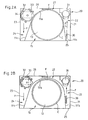
figure 2A est une vue schématique de dessus illustrant la répartition des organes de fonctionnement dans un four à micro-ondes conforme au premier mode de réalisation de l'invention ; - la
figure 2B est une vue analogue à lafigure 2A , illustrant un deuxième mode de réalisation de l'invention ; et - la
figure 3 est une vue en perspective illustrant un four à micro-ondes conforme au premier mode de réalisation de l'invention. - On va décrire tout d'abord en référence à la
figure 1 , une enceinte de cuisson 10 pour un four à micro-ondes conforme à un premier mode de réalisation de l'invention. - Il s'agit par exemple et de manière non limitative d'un four à micro-ondes de petit volume, dont l'enceinte de cuisson 10 peut avoir typiquement un volume de 17 litres.
- Ce type de four à micro-ondes est généralement relativement compact de manière à pouvoir être encastré dans une niche, ayant typiquement une largeur de 500 cm sur 350 cm de hauteur.
- L'enceinte de cuisson 10 comporte de manière classique un fond 12 et une paroi 11 délimitant l'enceinte de cuisson.
- Cette paroi 11 est sensiblement verticale et suit le contour du fond 12.
- Un plateau, dont l'emplacement est référencé 13 à la
figure 1 , est monté en rotation dans le fond 12 de l'enceinte de cuisson 10. - Une paroi supérieure 14 permet d'obturer l'enceinte de cuisson 10 dans sa partie supérieure.
- Conformément à l'invention, la paroi 11 délimitant l'enceinte de cuisson comprend au moins une portion de paroi elliptique 11a autour du plateau 13.
- Ici, cette portion de paroi 11a est tangente au plateau 13 et épouse un cercle circonscrit C au plateau (voir
figure 2A ). - Dans ce mode de réalisation, le plateau est lui-même circulaire de telle sorte que la portion de paroi 11a épouse parfaitement le contour C du plateau.
- Bien entendu, ce plateau pourrait être carré de telle sorte que cette portion de paroi 11a épouserait la forme du cercle circonscrit au plateau, c'est-à-dire le cercle passant par les coins d'un plateau carré.
- Cette portion de paroi 11a de l'enceinte de cuisson 10 est opposée à l'ouverture 15 de l'enceinte débouchant sur la façade du four.
- Ainsi, cette portion de paroi 11a forme la partie arrière de l'enceinte de cuisson 10.
- Comme mieux illustré à la
figure 2 , cette portion de paroi 11a épouse sensiblement 40 % du cercle circonscrit C au plateau 13. - Elle se prolonge ensuite par deux parois latérales 11b, 11c en direction de la façade du four.
- Ces parois latérales 11b, 11c, sensiblement planes, ne sont pas perpendiculaires à la façade du four mais au contraire inclinées de telle sorte que l'enceinte de cuisson est évasée en direction de l'ouverture 15 de l'enceinte 10.
- Cette partie évasée vers l'avant de l'enceinte de cuisson facilite la mise en place et le retrait d'un plat sur le plateau tournant 13.
- En outre, l'ouverture 15 dans laquelle débouche l'enceinte de cuisson 10 occupe la totalité de la façade du four.
- On peut ainsi obtenir une cavité dont la largeur représente sensiblement 85 % de la largeur totale de four à micro-ondes. En comparaison, les fours aujourd'hui ont une enceinte de cuisson dont la largeur ne dépasse pas 65 % de la largeur totale du four.
- Le volume de l'enceinte de cuisson peut ainsi atteindre 21 litres tout en conservant au four des dimensions compactes, lui permettant d'être encastré dans une niche de 500 cm de largeur sur 350 cm de hauteur et 310 cm de profondeur.
- L'enceinte de cuisson 10 peut occuper environ 43 % du volume global du four à micro-ondes.
- Les dimensions du plateau tournant 11 peuvent également atteindre 28 cm de diamètre, et permettre l'utilisation de plats de cuisson de plus grande taille comparativement à ceux utilisables dans un four à micro-ondes de 17 litres classique, dans lequel le plateau tournant a un diamètre sensiblement égal à 23 cm.
- Grâce à sa forme arrondie sensiblement circulaire dans sa partie arrière, la cavité 10 peut être réalisée en tôle peinte ou inoxydable à partir d'une, deux ou trois pièces selon sa complexité.
- Si elle ne comprend qu'une seule pièce, cette paroi latérale 11 de l'enceinte de cuisson 10 peut être réalisée par emboutissage d'une tôle.
- A partir de deux ou trois pièces, les différentes parties de cavité peuvent être réalisées par emboutissage et pliage, puis assemblées les unes aux autres par soudage.
- Les pièces en tôle peuvent également être pliées ensemble pour être assemblées (technique de clinchage).
- En comparaison, une enceinte traditionnelle parallélépipédique, comporte six plaques embouties et assemblées.
- On obtient ainsi, grâce à la réduction du nombre de pièces, une diminution du coût de fabrication d'une enceinte de cuisson conforme à l'invention.
- Alternativement, la forme semi-circulaire de cette enceinte de cuisson peut permettre sa réalisation par moulage ou injection d'alliages métalliques ou de matériaux composites chargés de métaux, par exemple à base d'un thermoplastique.
- On obtient une enceinte de cuisson dont le volume utile est proche du volume occupé par le plat de cuisson en rotation à l'intérieur de l'enceinte de cuisson.
- Comme illustré à la
figure 2B , la forme de la portion de paroi arrière 11'a pourrait être également elliptique et s'étendre au voisinage du plateau 13. Dans ce deuxième mode de réalisation, seule la forme de la paroi arrière 11'a et des parois latérales 11'b, 11'c est modifiée par rapport à l'exemple de réalisation de lafigure 2A . - Comme bien illustré aux
figures 2A et 2B , cette forme semi-circulaire ou elliptique de l'enceinte de cuisson 10 permet de répartir les organes de fonctionnement du four de part et d'autre de cette enceinte de cuisson 10. - Ainsi, de manière classique, l'enceinte de cuisson 10 est logée à l'intérieur de la carrosserie 20 du four de forme parallélépipédique.
- Ici, une carte électronique 30 et des moyens de ventilation 31 sont disposés entre l'enceinte de cuisson 10 et un premier panneau latéral 21 de la carrosserie du four.
- Cette carte électronique 30 et les moyens de ventilation 31 occupent ainsi l'espace libre 22 ménagé entre la paroi latérale 11b, 11'b et la paroi en arc de cercle 11a ou elliptique 11'a de l'enceinte de cuisson 10 et la carrosserie 20 du four.
- Symétriquement, le transformateur électrique 32, le générateur de micro-ondes ou magnétron 33 et le guide d'ondes 34 sont disposés entre l'enceinte de cuisson 10 et un second panneau latéral 23 de la carrosserie 20 du four.
- Ces moyens de génération de micro-ondes occupent ainsi l'espace libre 24 ménagé entre la paroi latérale 11c, 11'c et la paroi en arc de cercle 11a ou elliptique 11'a de l'enceinte de cuisson 10 et la carrosserie 20 du four.
- L'inclinaison des parois latérales 11b, 11'b, 11c, 11'c par rapport à la façade du four peut être différente de telle sorte que le premier espace libre 22 est légèrement plus petit que le second espace libre 24, adapté à loger des organes de fonctionnement plus encombrants (transformateur 32, magnétron 33 et guide d'ondes 34).
- L'enceinte de cuisson 10 débouchant sur la quasi-totalité de la façade 25 du four, les organes de fonctionnement 30-34 sont invisibles du côté de la façade 25 du four.
- Contrairement aux fours à micro-ondes classiques, dans lesquels toute la masse du four est concentrée sur un même côté du four, on obtient ici un four à micro-ondes mieux équilibré grâce à la répartition des organes de commande de part et d'autre de l'enceinte de cuisson 10.
- De plus, en supprimant la concentration des organes de fonctionnement du four en un même espace, on favorise la gestion de l'aéraulique du four, notamment afin de limiter l'échauffement de la carte électronique de commande 30, du magnétron 33 et du transformateur électrique 32.
- Afin de pouvoir gérer le refroidissement des organes de fonctionnement grâce à un moyen de ventilation unique, un espace libre 27 existe entre le panneau arrière 26 de la carrosserie 20 du four et la paroi 11 de l'enceinte de cuisson 10.
- Plus particulièrement, l'espace libre 27 s'étend entre la paroi elliptique 11'a ou en arc de cercle 11a de l'enceinte de cuisson 10 et le panneau arrière 26 de la carrosserie 20 du four.
- On utilise alors comme moyen de ventilation, un ventilateur tangentiel 31 disposé entre la carte électronique de commande 30 et les autres organes de fonctionnement 32-34 disposés de l'autre côté 24 de l'enceinte de cuisson 10.
- La carte électronique de commande 30 est disposée en amont du ventilateur tangentiel 31 suivant un sens de circulation de l'air aspiré par le ventilateur 31 représenté par les flèches F.
- Ainsi, de l'air frais et sec est aspiré par le ventilateur tangentiel 31 pour refroidir la carte électronique de commande 30.
- L'air ainsi aspiré est ensuite dirigé au travers de l'espace libre 27 de l'autre côté 24 du four pour refroidir le transformateur 32, et le générateur de micro-ondes 33, tous deux sources de chaleur importantes.
- Un unique ventilateur tangentiel 31 permet ainsi d'assurer la circulation de l'air à l'intérieur du four à micro-ondes, en aspirant l'air dans l'espace 22 sur un premier côté de l'enceinte de cuisson 10 et en soufflant de l'air en direction de l'espace 24 sur le second côté de l'enceinte de cuisson 10 via l'espace libre 27.
- Comme illustré à la
figure 3 , le bandeau de commande 29 peut être disposé sur la porte 28 du four, ou bien encore au-dessus ou en dessous de celle-ci. - De préférence, le transformateur 32, le générateur de micro-ondes 33 et le guide d'ondes 34 sont superposés à côté de l'enceinte de cuisson 10.
- Plus précisément, le générateur de micro-ondes ou magnétron 33 est positionné de telle sorte que son antenne émettrice d'ondes est disposée verticalement et dirigée vers le bas.
- Le guide d'ondes 34 est ainsi situé directement sous le générateur de micro-ondes 33 de telle sorte que l'antenne de ce dernier débouche dans le guide d'ondes 34.
- Ce guide d'ondes 34 est positionné en partie haute de l'enceinte de cuisson 10 afin de favoriser l'émission de micro-ondes à l'intérieur de cette enceinte de cuisson.
- On obtient ainsi un four à micro-ondes qui permet d'optimiser le volume utile de cuisson tout en restant relativement compact.
- En outre, le refroidissement des différents organes de fonctionnement de ce four est amélioré grâce à la disposition de ces organes de fonctionnement de part et d'autre de l'enceinte de cuisson et à l'utilisation d'un ventilateur tangentiel permettant d'organiser la circulation de l'air tout autour de l'enceinte de cuisson 10.
- Bien entendu, de nombreuses modifications peuvent être apportées à l'exemple de réalisation décrit ci-dessus sans sortir du cadre de l'invention.
- Ainsi, l'enceinte de cuisson elliptique peut être utilisée dans des fours à micro-ondes de dimensions quelconques, et notamment dans des fours de 24 ou 30 litres.
Claims (8)
- Four à micro-ondes comprenant une enceinte de cuisson (10) ayant un fond (12) et une paroi (11) délimitant l'enceinte de cuisson (10), et un plateau (13) monté en rotation dans le fond (12) de l'enceinte de cuisson (10), ladite paroi (11) de l'enceinte de cuisson (10) comprenant au moins une portion de paroi circulaire ou elliptique (11a, 11'a) autour du plateau (13), caractérisé en ce que ladite paroi (11) de l'enceinte de cuisson (10) est évasée en direction de l'ouverture (15) de l'enceinte débouchant sur la façade (25) du four.
- Four à micro-ondes conforme à la revendication 1, caractérisé en ce que ladite portion de paroi (11a) épouse un cercle circonscrit (C) au plateau (13).
- Four à micro-ondes conforme à l'une des revendications 1 ou 2, caractérisé en ce que ladite portion de paroi (11a, 11'a) de l'enceinte de cuisson (10) est opposée à l'ouverture (15) de l'enceinte débouchant sur la façade (25) du four.
- Four à micro-ondes conforme à l'une des revendications 1 à 3, caractérisé en ce que ladite portion de paroi (11a) épouse sensiblement 40 % d'un cercle circonscrit (C) au plateau (13).
- Four à micro-ondes conforme à l'une des revendications 1 à 4, caractérisé en ce que des organes de fonctionnement du four comprenant au moins un transformateur électrique (32), un générateur de micro-ondes (33), un guide d'ondes (34) et une carte électronique de commande (30), sont disposés de part et d'autre de l'enceinte de cuisson (10).
- Four à micro-ondes conforme à la revendication 5, caractérisé en ce que l'enceinte de cuisson (10) est logée à l'intérieur de la carrosserie (20) du four sensiblement parallélépipédique, un espace libre (27) étant ménagé entre un panneau arrière (26) de la carrosserie du four (20) et la paroi (11) de l'enceinte de cuisson (10).
- Four à micro-ondes conforme à la revendication 6, caractérisé en ce que la carte électronique de commande (30) et des moyens de ventilation (31) sont disposés entre l'enceinte de cuisson (10) et un premier panneau latéral (21) de la carrosserie (20) du four, et le transformateur électrique (32), le générateur de micro-ondes (33) et le guide d'ondes (34) sont disposés entre l'enceinte de cuisson (10) et un second panneau latéral (23) de la carrosserie (20) du four.
- Four à micro-ondes conforme à la revendication 7, caractérisé en ce que les moyens de ventilation sont constitués d'un ventilateur tangentiel (31) disposé en aval de la carte électronique de commande (30) suivant un sens de circulation (F) de l'air aspiré par le ventilateur (31).
Applications Claiming Priority (2)
| Application Number | Priority Date | Filing Date | Title |
|---|---|---|---|
| FR0016151 | 2000-12-12 | ||
| FR0016151A FR2817948B1 (fr) | 2000-12-12 | 2000-12-12 | Four a micro-ondes |
Publications (2)
| Publication Number | Publication Date |
|---|---|
| EP1215943A1 EP1215943A1 (fr) | 2002-06-19 |
| EP1215943B1 true EP1215943B1 (fr) | 2008-11-12 |
Family
ID=8857543
Family Applications (1)
| Application Number | Title | Priority Date | Filing Date |
|---|---|---|---|
| EP01403151A Expired - Lifetime EP1215943B1 (fr) | 2000-12-12 | 2001-12-06 | Four à micro-ondes |
Country Status (5)
| Country | Link |
|---|---|
| EP (1) | EP1215943B1 (fr) |
| AT (1) | ATE414399T1 (fr) |
| DE (1) | DE60136522D1 (fr) |
| ES (1) | ES2316424T3 (fr) |
| FR (1) | FR2817948B1 (fr) |
Families Citing this family (7)
| Publication number | Priority date | Publication date | Assignee | Title |
|---|---|---|---|---|
| CN100504183C (zh) * | 2004-11-26 | 2009-06-24 | 乐金电子(天津)电器有限公司 | 微波炉 |
| KR100862112B1 (ko) * | 2006-09-01 | 2008-10-09 | 엘지전자 주식회사 | 조리기기 |
| US7825358B2 (en) | 2006-09-01 | 2010-11-02 | Lg Electronics Inc. | Cooking apparatus having rear component space |
| KR100901890B1 (ko) | 2006-09-12 | 2009-06-10 | 엘지전자 주식회사 | 조리기기 |
| KR20080024025A (ko) | 2006-09-12 | 2008-03-17 | 엘지전자 주식회사 | 조리기기 |
| EP2755444A3 (fr) * | 2012-12-24 | 2015-02-25 | LG Electronics, Inc. | Appareil de cuisson et son procédé de fabrication |
| PL3608594T3 (pl) * | 2018-08-10 | 2022-02-07 | Bonferraro S.P.A. | Mufla do pieca konwekcyjnego i piec zawierający muflę |
Family Cites Families (5)
| Publication number | Priority date | Publication date | Assignee | Title |
|---|---|---|---|---|
| JPH01314816A (ja) * | 1988-06-14 | 1989-12-20 | Mitsubishi Electric Corp | 加熱調理器 |
| JPH03140712A (ja) * | 1989-10-26 | 1991-06-14 | Brother Ind Ltd | 電子レンジ |
| GB2266039A (en) * | 1992-04-10 | 1993-10-13 | Frazer Design Consultants Ltd | Microwave oven with a cylindrical oven cavity |
| JP3066283B2 (ja) * | 1995-03-13 | 2000-07-17 | 三洋電機株式会社 | 電子レンジ |
| JPH10172751A (ja) * | 1996-12-04 | 1998-06-26 | Matsushita Electric Ind Co Ltd | 電子レンジ |
-
2000
- 2000-12-12 FR FR0016151A patent/FR2817948B1/fr not_active Expired - Fee Related
-
2001
- 2001-12-06 EP EP01403151A patent/EP1215943B1/fr not_active Expired - Lifetime
- 2001-12-06 AT AT01403151T patent/ATE414399T1/de not_active IP Right Cessation
- 2001-12-06 ES ES01403151T patent/ES2316424T3/es not_active Expired - Lifetime
- 2001-12-06 DE DE60136522T patent/DE60136522D1/de not_active Expired - Fee Related
Also Published As
| Publication number | Publication date |
|---|---|
| DE60136522D1 (de) | 2008-12-24 |
| FR2817948B1 (fr) | 2003-06-20 |
| ES2316424T3 (es) | 2009-04-16 |
| ATE414399T1 (de) | 2008-11-15 |
| EP1215943A1 (fr) | 2002-06-19 |
| FR2817948A1 (fr) | 2002-06-14 |
Similar Documents
| Publication | Publication Date | Title |
|---|---|---|
| EP0362022B1 (fr) | Four de cuisson mixte | |
| USD520298S1 (en) | Cooking grill | |
| USD432852S (en) | Portable stove | |
| CA2589628C (fr) | Etagere, en particulier pour des installations refrigerees, adaptee pour supporter au moins un accessoire, et accessoires correspondants | |
| USD503868S1 (en) | Barbecue grill | |
| US10190783B2 (en) | Convection cooking appliance with circular air flow system | |
| USD500769S1 (en) | Compressor shroud | |
| EP0735324A1 (fr) | Porte de four simplifiée avec module amovible | |
| FR2945856A1 (fr) | Unite exterieure | |
| KR960034871A (ko) | 전자레인지 | |
| FR2524616A1 (fr) | Appareil de cuisson micro-onde | |
| FR3003338A1 (fr) | Table de cuisson comprenant un dispositif de fixation d'au moins un plateau de support d'au moins un moyen de chauffage sur un carter | |
| EP1215943A1 (fr) | Four à micro-ondes | |
| USD503582S1 (en) | Outdoor barbecue grill assembly | |
| CN101660777A (zh) | 加热烹调器 | |
| EP2340718B1 (fr) | Appareil électrique prévu pour la réalisation de préparations culinaires en portions séparées | |
| EP0376791B1 (fr) | Dispositif de support des moyens de commande pour appareil ménager | |
| EP1843101A2 (fr) | Dispositif d'échangeur thermique de brûleur à gaz | |
| USD1035727S1 (en) | Portable refrigerator | |
| EP1241923A1 (fr) | Four de chauffage par micro-ondes | |
| BE1013297A3 (fr) | Foyer multifonctionnel. | |
| USD550994S1 (en) | Portions of a left side shelf and cabinet incline | |
| USD518035S1 (en) | Base for broadband router enclosure | |
| EP1239224B1 (fr) | Four électrique domestique encastrable | |
| US20130082159A1 (en) | Reinforced leg device for charcoal broiler |
Legal Events
| Date | Code | Title | Description |
|---|---|---|---|
| PUAI | Public reference made under article 153(3) epc to a published international application that has entered the european phase |
Free format text: ORIGINAL CODE: 0009012 |
|
| AK | Designated contracting states |
Kind code of ref document: A1 Designated state(s): AT BE CH CY DE DK ES FI FR GB GR IE IT LI LU MC NL PT SE TR |
|
| AX | Request for extension of the european patent |
Free format text: AL;LT;LV;MK;RO;SI |
|
| 17P | Request for examination filed |
Effective date: 20020927 |
|
| AKX | Designation fees paid |
Designated state(s): AT BE CH CY DE DK ES FI FR GB GR IE IT LI LU MC NL PT SE TR |
|
| RAP1 | Party data changed (applicant data changed or rights of an application transferred) |
Owner name: BRANDT INDUSTRIES |
|
| 17Q | First examination report despatched |
Effective date: 20070529 |
|
| GRAP | Despatch of communication of intention to grant a patent |
Free format text: ORIGINAL CODE: EPIDOSNIGR1 |
|
| RAP1 | Party data changed (applicant data changed or rights of an application transferred) |
Owner name: FAGORBRANDT SAS |
|
| GRAS | Grant fee paid |
Free format text: ORIGINAL CODE: EPIDOSNIGR3 |
|
| GRAA | (expected) grant |
Free format text: ORIGINAL CODE: 0009210 |
|
| AK | Designated contracting states |
Kind code of ref document: B1 Designated state(s): AT BE CH CY DE DK ES FI FR GB GR IE IT LI LU MC NL PT SE TR |
|
| REG | Reference to a national code |
Ref country code: GB Ref legal event code: FG4D Free format text: NOT ENGLISH |
|
| REG | Reference to a national code |
Ref country code: CH Ref legal event code: EP |
|
| REG | Reference to a national code |
Ref country code: IE Ref legal event code: FG4D Free format text: LANGUAGE OF EP DOCUMENT: FRENCH |
|
| REF | Corresponds to: |
Ref document number: 60136522 Country of ref document: DE Date of ref document: 20081224 Kind code of ref document: P |
|
| REG | Reference to a national code |
Ref country code: ES Ref legal event code: FG2A Ref document number: 2316424 Country of ref document: ES Kind code of ref document: T3 |
|
| PG25 | Lapsed in a contracting state [announced via postgrant information from national office to epo] |
Ref country code: AT Free format text: LAPSE BECAUSE OF FAILURE TO SUBMIT A TRANSLATION OF THE DESCRIPTION OR TO PAY THE FEE WITHIN THE PRESCRIBED TIME-LIMIT Effective date: 20081112 |
|
| NLV1 | Nl: lapsed or annulled due to failure to fulfill the requirements of art. 29p and 29m of the patents act | ||
| PG25 | Lapsed in a contracting state [announced via postgrant information from national office to epo] |
Ref country code: NL Free format text: LAPSE BECAUSE OF FAILURE TO SUBMIT A TRANSLATION OF THE DESCRIPTION OR TO PAY THE FEE WITHIN THE PRESCRIBED TIME-LIMIT Effective date: 20081112 Ref country code: FI Free format text: LAPSE BECAUSE OF FAILURE TO SUBMIT A TRANSLATION OF THE DESCRIPTION OR TO PAY THE FEE WITHIN THE PRESCRIBED TIME-LIMIT Effective date: 20081112 |
|
| PGFP | Annual fee paid to national office [announced via postgrant information from national office to epo] |
Ref country code: DE Payment date: 20090211 Year of fee payment: 8 |
|
| BERE | Be: lapsed |
Owner name: FAGORBRANDT SAS Effective date: 20081231 |
|
| PGFP | Annual fee paid to national office [announced via postgrant information from national office to epo] |
Ref country code: GB Payment date: 20090210 Year of fee payment: 8 |
|
| REG | Reference to a national code |
Ref country code: IE Ref legal event code: FD4D |
|
| PG25 | Lapsed in a contracting state [announced via postgrant information from national office to epo] |
Ref country code: DK Free format text: LAPSE BECAUSE OF FAILURE TO SUBMIT A TRANSLATION OF THE DESCRIPTION OR TO PAY THE FEE WITHIN THE PRESCRIBED TIME-LIMIT Effective date: 20081112 Ref country code: IE Free format text: LAPSE BECAUSE OF FAILURE TO SUBMIT A TRANSLATION OF THE DESCRIPTION OR TO PAY THE FEE WITHIN THE PRESCRIBED TIME-LIMIT Effective date: 20081112 Ref country code: MC Free format text: LAPSE BECAUSE OF NON-PAYMENT OF DUE FEES Effective date: 20081231 |
|
| REG | Reference to a national code |
Ref country code: CH Ref legal event code: PL |
|
| PG25 | Lapsed in a contracting state [announced via postgrant information from national office to epo] |
Ref country code: SE Free format text: LAPSE BECAUSE OF FAILURE TO SUBMIT A TRANSLATION OF THE DESCRIPTION OR TO PAY THE FEE WITHIN THE PRESCRIBED TIME-LIMIT Effective date: 20090212 Ref country code: PT Free format text: LAPSE BECAUSE OF FAILURE TO SUBMIT A TRANSLATION OF THE DESCRIPTION OR TO PAY THE FEE WITHIN THE PRESCRIBED TIME-LIMIT Effective date: 20090413 |
|
| PGFP | Annual fee paid to national office [announced via postgrant information from national office to epo] |
Ref country code: IT Payment date: 20090226 Year of fee payment: 8 |
|
| PLBE | No opposition filed within time limit |
Free format text: ORIGINAL CODE: 0009261 |
|
| STAA | Information on the status of an ep patent application or granted ep patent |
Free format text: STATUS: NO OPPOSITION FILED WITHIN TIME LIMIT |
|
| PG25 | Lapsed in a contracting state [announced via postgrant information from national office to epo] |
Ref country code: BE Free format text: LAPSE BECAUSE OF NON-PAYMENT OF DUE FEES Effective date: 20081231 |
|
| 26N | No opposition filed |
Effective date: 20090813 |
|
| PG25 | Lapsed in a contracting state [announced via postgrant information from national office to epo] |
Ref country code: CH Free format text: LAPSE BECAUSE OF NON-PAYMENT OF DUE FEES Effective date: 20081231 Ref country code: LI Free format text: LAPSE BECAUSE OF NON-PAYMENT OF DUE FEES Effective date: 20081231 |
|
| PG25 | Lapsed in a contracting state [announced via postgrant information from national office to epo] |
Ref country code: CY Free format text: LAPSE BECAUSE OF FAILURE TO SUBMIT A TRANSLATION OF THE DESCRIPTION OR TO PAY THE FEE WITHIN THE PRESCRIBED TIME-LIMIT Effective date: 20081112 Ref country code: LU Free format text: LAPSE BECAUSE OF NON-PAYMENT OF DUE FEES Effective date: 20081206 |
|
| GBPC | Gb: european patent ceased through non-payment of renewal fee |
Effective date: 20091206 |
|
| PG25 | Lapsed in a contracting state [announced via postgrant information from national office to epo] |
Ref country code: TR Free format text: LAPSE BECAUSE OF FAILURE TO SUBMIT A TRANSLATION OF THE DESCRIPTION OR TO PAY THE FEE WITHIN THE PRESCRIBED TIME-LIMIT Effective date: 20081112 |
|
| PG25 | Lapsed in a contracting state [announced via postgrant information from national office to epo] |
Ref country code: GR Free format text: LAPSE BECAUSE OF FAILURE TO SUBMIT A TRANSLATION OF THE DESCRIPTION OR TO PAY THE FEE WITHIN THE PRESCRIBED TIME-LIMIT Effective date: 20090213 |
|
| PG25 | Lapsed in a contracting state [announced via postgrant information from national office to epo] |
Ref country code: DE Free format text: LAPSE BECAUSE OF NON-PAYMENT OF DUE FEES Effective date: 20100701 |
|
| PG25 | Lapsed in a contracting state [announced via postgrant information from national office to epo] |
Ref country code: GB Free format text: LAPSE BECAUSE OF NON-PAYMENT OF DUE FEES Effective date: 20091206 |
|
| PG25 | Lapsed in a contracting state [announced via postgrant information from national office to epo] |
Ref country code: IT Free format text: LAPSE BECAUSE OF NON-PAYMENT OF DUE FEES Effective date: 20091206 |
|
| PGFP | Annual fee paid to national office [announced via postgrant information from national office to epo] |
Ref country code: ES Payment date: 20101221 Year of fee payment: 10 |
|
| REG | Reference to a national code |
Ref country code: ES Ref legal event code: FD2A Effective date: 20130704 |
|
| PG25 | Lapsed in a contracting state [announced via postgrant information from national office to epo] |
Ref country code: ES Free format text: LAPSE BECAUSE OF NON-PAYMENT OF DUE FEES Effective date: 20111207 |
|
| REG | Reference to a national code |
Ref country code: FR Ref legal event code: PLFP Year of fee payment: 15 |
|
| REG | Reference to a national code |
Ref country code: FR Ref legal event code: TP Owner name: GROUPE BRANDT, FR Effective date: 20160420 |
|
| REG | Reference to a national code |
Ref country code: FR Ref legal event code: GC Effective date: 20160426 |
|
| REG | Reference to a national code |
Ref country code: FR Ref legal event code: PLFP Year of fee payment: 16 |
|
| REG | Reference to a national code |
Ref country code: FR Ref legal event code: PLFP Year of fee payment: 17 |
|
| PGFP | Annual fee paid to national office [announced via postgrant information from national office to epo] |
Ref country code: FR Payment date: 20191230 Year of fee payment: 19 |
|
| PG25 | Lapsed in a contracting state [announced via postgrant information from national office to epo] |
Ref country code: FR Free format text: LAPSE BECAUSE OF NON-PAYMENT OF DUE FEES Effective date: 20201231 |