EP1215893A1 - Antenna apparatus for digital cameras incorporating wideband RF transceivers - Google Patents
Antenna apparatus for digital cameras incorporating wideband RF transceivers Download PDFInfo
- Publication number
- EP1215893A1 EP1215893A1 EP01204629A EP01204629A EP1215893A1 EP 1215893 A1 EP1215893 A1 EP 1215893A1 EP 01204629 A EP01204629 A EP 01204629A EP 01204629 A EP01204629 A EP 01204629A EP 1215893 A1 EP1215893 A1 EP 1215893A1
- Authority
- EP
- European Patent Office
- Prior art keywords
- camera
- transceiver
- antenna
- user interface
- digital camera
- Prior art date
- Legal status (The legal status is an assumption and is not a legal conclusion. Google has not performed a legal analysis and makes no representation as to the accuracy of the status listed.)
- Withdrawn
Links
Images


Classifications
-
- H—ELECTRICITY
- H04—ELECTRIC COMMUNICATION TECHNIQUE
- H04N—PICTORIAL COMMUNICATION, e.g. TELEVISION
- H04N1/00—Scanning, transmission or reproduction of documents or the like, e.g. facsimile transmission; Details thereof
- H04N1/00127—Connection or combination of a still picture apparatus with another apparatus, e.g. for storage, processing or transmission of still picture signals or of information associated with a still picture
- H04N1/00281—Connection or combination of a still picture apparatus with another apparatus, e.g. for storage, processing or transmission of still picture signals or of information associated with a still picture with a telecommunication apparatus, e.g. a switched network of teleprinters for the distribution of text-based information, a selective call terminal
- H04N1/00315—Connection or combination of a still picture apparatus with another apparatus, e.g. for storage, processing or transmission of still picture signals or of information associated with a still picture with a telecommunication apparatus, e.g. a switched network of teleprinters for the distribution of text-based information, a selective call terminal with a radio transmission apparatus
-
- H—ELECTRICITY
- H01—ELECTRIC ELEMENTS
- H01Q—ANTENNAS, i.e. RADIO AERIALS
- H01Q1/00—Details of, or arrangements associated with, antennas
- H01Q1/12—Supports; Mounting means
- H01Q1/22—Supports; Mounting means by structural association with other equipment or articles
-
- H—ELECTRICITY
- H01—ELECTRIC ELEMENTS
- H01Q—ANTENNAS, i.e. RADIO AERIALS
- H01Q1/00—Details of, or arrangements associated with, antennas
- H01Q1/12—Supports; Mounting means
- H01Q1/22—Supports; Mounting means by structural association with other equipment or articles
- H01Q1/24—Supports; Mounting means by structural association with other equipment or articles with receiving set
- H01Q1/241—Supports; Mounting means by structural association with other equipment or articles with receiving set used in mobile communications, e.g. GSM
- H01Q1/242—Supports; Mounting means by structural association with other equipment or articles with receiving set used in mobile communications, e.g. GSM specially adapted for hand-held use
- H01Q1/245—Supports; Mounting means by structural association with other equipment or articles with receiving set used in mobile communications, e.g. GSM specially adapted for hand-held use with means for shaping the antenna pattern, e.g. in order to protect user against rf exposure
-
- H—ELECTRICITY
- H01—ELECTRIC ELEMENTS
- H01Q—ANTENNAS, i.e. RADIO AERIALS
- H01Q19/00—Combinations of primary active antenna elements and units with secondary devices, e.g. with quasi-optical devices, for giving the antenna a desired directional characteristic
- H01Q19/28—Combinations of primary active antenna elements and units with secondary devices, e.g. with quasi-optical devices, for giving the antenna a desired directional characteristic using a secondary device in the form of two or more substantially straight conductive elements
- H01Q19/30—Combinations of primary active antenna elements and units with secondary devices, e.g. with quasi-optical devices, for giving the antenna a desired directional characteristic using a secondary device in the form of two or more substantially straight conductive elements the primary active element being centre-fed and substantially straight, e.g. Yagi antenna
-
- H—ELECTRICITY
- H01—ELECTRIC ELEMENTS
- H01Q—ANTENNAS, i.e. RADIO AERIALS
- H01Q3/00—Arrangements for changing or varying the orientation or the shape of the directional pattern of the waves radiated from an antenna or antenna system
- H01Q3/24—Arrangements for changing or varying the orientation or the shape of the directional pattern of the waves radiated from an antenna or antenna system varying the orientation by switching energy from one active radiating element to another, e.g. for beam switching
-
- H—ELECTRICITY
- H04—ELECTRIC COMMUNICATION TECHNIQUE
- H04B—TRANSMISSION
- H04B7/00—Radio transmission systems, i.e. using radiation field
- H04B7/02—Diversity systems; Multi-antenna system, i.e. transmission or reception using multiple antennas
- H04B7/04—Diversity systems; Multi-antenna system, i.e. transmission or reception using multiple antennas using two or more spaced independent antennas
- H04B7/06—Diversity systems; Multi-antenna system, i.e. transmission or reception using multiple antennas using two or more spaced independent antennas at the transmitting station
- H04B7/0602—Diversity systems; Multi-antenna system, i.e. transmission or reception using multiple antennas using two or more spaced independent antennas at the transmitting station using antenna switching
- H04B7/0608—Antenna selection according to transmission parameters
-
- H—ELECTRICITY
- H04—ELECTRIC COMMUNICATION TECHNIQUE
- H04B—TRANSMISSION
- H04B7/00—Radio transmission systems, i.e. using radiation field
- H04B7/02—Diversity systems; Multi-antenna system, i.e. transmission or reception using multiple antennas
- H04B7/04—Diversity systems; Multi-antenna system, i.e. transmission or reception using multiple antennas using two or more spaced independent antennas
- H04B7/08—Diversity systems; Multi-antenna system, i.e. transmission or reception using multiple antennas using two or more spaced independent antennas at the receiving station
- H04B7/0802—Diversity systems; Multi-antenna system, i.e. transmission or reception using multiple antennas using two or more spaced independent antennas at the receiving station using antenna selection
- H04B7/0805—Diversity systems; Multi-antenna system, i.e. transmission or reception using multiple antennas using two or more spaced independent antennas at the receiving station using antenna selection with single receiver and antenna switching
- H04B7/0814—Diversity systems; Multi-antenna system, i.e. transmission or reception using multiple antennas using two or more spaced independent antennas at the receiving station using antenna selection with single receiver and antenna switching based on current reception conditions, e.g. switching to different antenna when signal level is below threshold
-
- H—ELECTRICITY
- H04—ELECTRIC COMMUNICATION TECHNIQUE
- H04B—TRANSMISSION
- H04B7/00—Radio transmission systems, i.e. using radiation field
- H04B7/02—Diversity systems; Multi-antenna system, i.e. transmission or reception using multiple antennas
- H04B7/12—Frequency diversity
-
- H—ELECTRICITY
- H04—ELECTRIC COMMUNICATION TECHNIQUE
- H04N—PICTORIAL COMMUNICATION, e.g. TELEVISION
- H04N1/00—Scanning, transmission or reproduction of documents or the like, e.g. facsimile transmission; Details thereof
- H04N1/00127—Connection or combination of a still picture apparatus with another apparatus, e.g. for storage, processing or transmission of still picture signals or of information associated with a still picture
- H04N1/00281—Connection or combination of a still picture apparatus with another apparatus, e.g. for storage, processing or transmission of still picture signals or of information associated with a still picture with a telecommunication apparatus, e.g. a switched network of teleprinters for the distribution of text-based information, a selective call terminal
-
- H—ELECTRICITY
- H04—ELECTRIC COMMUNICATION TECHNIQUE
- H04N—PICTORIAL COMMUNICATION, e.g. TELEVISION
- H04N23/00—Cameras or camera modules comprising electronic image sensors; Control thereof
- H04N23/50—Constructional details
-
- H—ELECTRICITY
- H04—ELECTRIC COMMUNICATION TECHNIQUE
- H04N—PICTORIAL COMMUNICATION, e.g. TELEVISION
- H04N23/00—Cameras or camera modules comprising electronic image sensors; Control thereof
- H04N23/60—Control of cameras or camera modules
- H04N23/63—Control of cameras or camera modules by using electronic viewfinders
- H04N23/631—Graphical user interfaces [GUI] specially adapted for controlling image capture or setting capture parameters
-
- H—ELECTRICITY
- H04—ELECTRIC COMMUNICATION TECHNIQUE
- H04N—PICTORIAL COMMUNICATION, e.g. TELEVISION
- H04N23/00—Cameras or camera modules comprising electronic image sensors; Control thereof
- H04N23/60—Control of cameras or camera modules
- H04N23/66—Remote control of cameras or camera parts, e.g. by remote control devices
- H04N23/661—Transmitting camera control signals through networks, e.g. control via the Internet
-
- H—ELECTRICITY
- H04—ELECTRIC COMMUNICATION TECHNIQUE
- H04N—PICTORIAL COMMUNICATION, e.g. TELEVISION
- H04N2101/00—Still video cameras
-
- H—ELECTRICITY
- H04—ELECTRIC COMMUNICATION TECHNIQUE
- H04N—PICTORIAL COMMUNICATION, e.g. TELEVISION
- H04N2201/00—Indexing scheme relating to scanning, transmission or reproduction of documents or the like, and to details thereof
- H04N2201/0008—Connection or combination of a still picture apparatus with another apparatus
- H04N2201/0063—Constructional details
Definitions
- This invention relates to digital cameras that incorporate digital wireless RF communication systems operating in a microwave band such as the 2.4 to 2.5 GHz ISM (Industrial Scientific and Medical) Band. Such communication is useful, for example, for sending digital imaging data at high data rates; e.g. rates equal and greater than 10 Mega bits per second (Mbps).
- a microwave band such as the 2.4 to 2.5 GHz ISM (Industrial Scientific and Medical) Band.
- ISM Industrial Scientific and Medical
- Short transmission times are needed in order to send and receive these large files quickly allowing the user freedom to do other things. At data rate speeds greater than 10Mbps, these large files can be sent in a second or two. Short transmission times would also reduce battery power consumption for portable devices like a digital camera.
- An additional desirable feature is being able to communicate at distances greater than 300 feet and also to communicate through walls. These features would enable digital cameras to communicate with utilization devices like photofinishing or multimedia equipment when the equipment is located inside a retail store, and the camera is being operated for example, inside an automobile from the parking lot of the store. Another useful feature would be for the wireless communication to be unlicensed and worldwide so that the digital camera could be taken on vacation and used in any country in the world without air time costs.
- the frequency band of operation determines size of the antenna needed. The higher the frequency of operation, the smaller the antenna needed since the wavelength of the signal is shorter. Because cameras are handheld portable devices, the overall small size of a camera is an important selling feature. Smaller invisible imbedded antennas are very desirable for appearance reasons in a digital camera. There are several radio frequency bands that could be used for such type of transmissions.
- One of the most attractive communication bands for such a digital communication system is the 2.4 to 2.5 GHz ISM Band since it is a microwave band with a quarter wavelength of about 1.2 inches, and that the band is unlicensed and the only band available internationally to date.
- This band for the wireless communication of digital images.
- One problem is the distortion of the antenna pattern due to human body effects.
- the user's hands and the closeness of the user's body to the digital camera alter the transmit and receive pattern of the antenna while holding the camera.
- Many types of antennas used in portable devices for operation in microwave bands are available in the marketplace today. They are typically retractable single stub monopoles, patch, F or L shaped antennas.
- Some recently developed antennas made of ceramic material are not much larger than the head of a pencil. While such antennas generally work well in wireless phones for instance, they all have antenna patterns with omnidirectional characteristics that do not work well when placed in a digital camera and held with both hands close to the torso of the body.
- GUI Graphic User Interface
- multipath fading Another problem with the use of the microwave band is the effect known as multipath fading on the propagation of the microwave signal.
- the effect of multipath fading on radio waves is a well known problem.
- the term multipath fading is used to describe the variations in signal strength that occur at a receiver during the time a signal is being sent. Fading occurs when a signal sent by a transmitter is reflected or blocked by a conductive medium such as a metal surface like a building, or the ground of the earth.
- the effects of multipath fading differ based on the physical characteristics of conductive obstructions versus the carrier frequency of the radio communication system, and the type of modulation technique employed. In general, the effects of multipath fading are greater at higher frequencies because the phenomenon of diffraction is slowed.
- One problem with using microwave bands is that the effect of multipath fading is also increased due to signal reflections and absorption by small objects and also by the human body.
- Diversity refers to a level of redundancy or duplication in order to achieve an improvement in performance under multipath fading conditions.
- Space or antenna diversity refers to the use of two or more antennas.
- Frequency diversity refers to the changing of carrier frequencies in order to avoid the multipath fading.
- an antenna apparatus for digital cameras that incorporates wireless RF transceivers for communicating digital images and an improved means of transmission and reception when operating in microwave bands in the presence of signal absorption and multipath fading-and the effects of the human body.
- a digital camera having a wideband RF transceiver including: a graphic user interface for displaying a camera control menu, the graphic user interface having a normal viewing axis; camera grips located on opposite sides of the camera body for holding the camera to operate the transceiver while viewing the graphic user interface; and a directional antenna arranged with respect to the camera to point away from a user of the camera and having a 90 ⁇ 10 degree vertical beam width centered on the horizon ⁇ 20 degrees, and a 180 ⁇ 20 degree horizontal beam width when the camera is held by the grips for normal viewing of the graphic user interface while operating the transceiver.
- the camer has the advantages that the hands and body of the camera user do not affect the communications of the camera.
- the camera can achieve a high data communication rate and the antenna has a small size due to the high frequency of operation of the transceiver.
- the camera has the additional advantage that communication is optimized when the camera is held in the intended position for viewing the graphic user interface.
- a typical wideband transceiver 10 in a digital camera 12 useful with an antenna arrangement of the present invention is shown.
- the term wideband means any RF transceiver capable of communication data rates of 10 megabits per second or faster.
- the camera 12 includes a lens 14 and an image sensor 16.
- the overall operation of the camera 12 is controlled by a microprocessor 18, which receives control inputs from a control panel 20, displays control instructions and images on a display 22, and manages images stored in a camera memory 24.
- the display 22 and control panel 20 together comprise a graphical user interface (GUI) 26.
- The-display 22 and control panel 20 can be integrated as a touch screen.
- An antenna array 27 including a pair of directional antennas 28 and 30 are connected to the transceiver 10 through an antenna switch 32.
- the transceiver 10 is controlled by the microprocessor 18 to transmit and receive digital image files and other information to and from other cameras and communication devices in the neighborhood of the camera 12.
- the antenna switch 32 is under control of the microprocessor 18 and can switch between directional antennas 28 and 30.
- the microprocessor 18 receives an RSSI (received signal strength indicator) signal from the transceiver and periodically switches back and forth (e.g. every few seconds) between the antennas to determine which provides the strongest RSSI signal. This provides spatial diversity to the transceiver.
- the microprocessor can monitor the rate of packet errors and switch between the antennas to minimize the packet error rate.
- the microprocessor 18 periodically signals the RF transceiver 10 via a frequency control line to change the carrier frequency of the RF transceiver 10, monitors a received signal strength indicator (RSSI) signal from the transceiver, and selects the carrier frequency that provides the strongest signal to the transceiver to provide frequency diversity to the wideband RF transceiver.
- RSSI received signal strength indicator
- the camera 12 may include a flash lamp 34 and a pair of grips 36 and 38 located on either side of lens 14.
- the camera grips 36 and 38 are located on opposite sides of the camera body for holding the camera to operate the transceiver while a camera user 40 (see Fig. 3) views the graphic user interface 26.
- the antenna array 27 is located for example on one side of the flash mechanism 34 where it is not covered by a user's hands on the hand grips.
- the directional antenna array 27 is arranged with respect to the camera to point away from a user of the camera and having a 90 ⁇ 10 degree vertical beam width centered on the horizon ⁇ 20 degrees, and a 180 ⁇ 20 degree horizontal beam width when the camera is held by the grips 36 and 38 for normal viewing of the graphic user interface 26 while operating the transceiver 10.
- an antenna array 27 includes a first antenna 28 having a radiating element 42 and a reflecting element 44.
- the elements would typically be one half wavelength or less long, e.g. about 6 cm or less for the 2.45 GHz band.
- the radiating element 42 is coupled to the transceiver by a balanced to unbalanced transformer (balun) 46, and the reflecting element 44 is connected to ground.
- the first and second antennas may be constructed from discrete elements and encapsulated in a block of plastic and mounted outside the body of a metal bodied camera.
- the antenna array may be formed by printing the antenna elements on a printed circuit board and the printed circuit board mounted inside a plastic bodied camera.
- the antenna elements could also be formed in the body of a plastic bodied camera as shown in Fig. 5.
- Fig. 5 shows a side view of the camera 12 with lens 14 and GUI 26.
- the antenna elements 42 and 48 are shown imbedded in the plastic case or outer enclosure of the camera body 56.
- the antenna elements are connected to the antenna switch 32 (not shown) which is located on the RF transceiver Printed Circuit Board (PCB) 41.
- the plastic case or outer enclosure 56 of the camera is lined with a conductive surface like a conductive paint or metal film to form a Faraday cage 54 about the electronics of the digital camera. Such conductive surfaces are most always used in electronic products to prevent the emissions of electromagnetic radiation.
- the Faraday cage 54 can as shown also be used as the reflector for the radiating elements to form a directional antenna array.
- the radiating elements could easily be modeled into the plastic outer case of the camera body. Small wires or a connector could be used to connect the radiating elements 42 and 48 to the RF transceiver PCB 41 .
- the antenna elements 42 and 48 can be encapsulated in a nonconductive material and mounted on the outside of the metal body, the metal body being used as an antenna reflector.
Abstract
A digital camera having a wideband RF transceiver, includes: a
graphic user interface for displaying a camera control menu, the graphic user
interface having a normal viewing axis; camera grips located on opposite sides of
the camera body for holding the camera to operate the transceiver while viewing
the graphic user interface; and a directional antenna arranged with respect to the
camera to point away from a user of the camera and having a 90 ± 10 degree
vertical beam width centered on the horizon ± 20 degrees, and a 180 ± 20 degree
horizontal beam width when the camera is held by the grips for normal viewing of
the graphic user interface while operating the transceiver.
Description
- This invention relates to digital cameras that incorporate digital wireless RF communication systems operating in a microwave band such as the 2.4 to 2.5 GHz ISM (Industrial Scientific and Medical) Band. Such communication is useful, for example, for sending digital imaging data at high data rates; e.g. rates equal and greater than 10 Mega bits per second (Mbps).
- With the advent of digital photography and file compression techniques like JPEG for still images and MPEG2 for video, the wireless transmission of digital files, for example between a transmitting device like a digital camera and a receiving device such as a personal computer or other image appliance such as a printer, has become a desirable feature. High data rate transmissions are very desirable because both digital images and streaming video represent a large amount of data (often greater than 1MByte in size) and short transmission times are needed.
- Short transmission times are needed in order to send and receive these large files quickly allowing the user freedom to do other things. At data rate speeds greater than 10Mbps, these large files can be sent in a second or two. Short transmission times would also reduce battery power consumption for portable devices like a digital camera.
- An additional desirable feature is being able to communicate at distances greater than 300 feet and also to communicate through walls. These features would enable digital cameras to communicate with utilization devices like photofinishing or multimedia equipment when the equipment is located inside a retail store, and the camera is being operated for example, inside an automobile from the parking lot of the store. Another useful feature would be for the wireless communication to be unlicensed and worldwide so that the digital camera could be taken on vacation and used in any country in the world without air time costs.
- One way to send files from digital cameras without wires is through the use of radio waves. A use of radio waves to perform image communication is described in US Patent 5,806,005 issued September 8, 1998 to Hull et al. This patent demonstrates a potential solution of moving digital images using a cellular telephone transmitter. Unfortunately this technique has very slow data rates (i.e. 9.6Kbps) due to the use of the cellular telephone and a large and cumbersome antenna. The cellular phone is physically too large to be incorporated into the body of the digital camera and results in a expensive system to both purchase and operate. The user of the system would not only need to purchase both the digital camera, connecting wire, and cellular phone but also pay by the minute for the air time (talk time) for using the cell phone. Worldwide use would be restricted and battery consumption would be high due to the slow 9.6Kbps transmission rate.
- One of the most important factors in determining the usefulness of the wireless system in a digital camera is in selecting the frequency band of operation. The frequency band also by way of its associated wavelength, determines size of the antenna needed. The higher the frequency of operation, the smaller the antenna needed since the wavelength of the signal is shorter. Because cameras are handheld portable devices, the overall small size of a camera is an important selling feature. Smaller invisible imbedded antennas are very desirable for appearance reasons in a digital camera. There are several radio frequency bands that could be used for such type of transmissions. One of the most attractive communication bands for such a digital communication system is the 2.4 to 2.5 GHz ISM Band since it is a microwave band with a quarter wavelength of about 1.2 inches, and that the band is unlicensed and the only band available internationally to date.
- There are however, several major problems that exist with the use of this band for the wireless communication of digital images. One problem is the distortion of the antenna pattern due to human body effects. The user's hands and the closeness of the user's body to the digital camera alter the transmit and receive pattern of the antenna while holding the camera. Many types of antennas used in portable devices for operation in microwave bands are available in the marketplace today. They are typically retractable single stub monopoles, patch, F or L shaped antennas. Some recently developed antennas made of ceramic material are not much larger than the head of a pencil. While such antennas generally work well in wireless phones for instance, they all have antenna patterns with omnidirectional characteristics that do not work well when placed in a digital camera and held with both hands close to the torso of the body.
- One important requirement in the wireless communication from a digital camera is the capability of the user to be able to view the Graphic User Interface (GUI) of the camera during operation. This means that the camera must transmit while being held by ones hands and while ones fingers operate the controls. In order for the transmission of the signal to be as efficient as possible, the antenna pattern should be designed in such a way as to avoid emitting energy at the human body.
- Another problem with the use of the microwave band is the effect known as multipath fading on the propagation of the microwave signal. The effect of multipath fading on radio waves is a well known problem. The term multipath fading is used to describe the variations in signal strength that occur at a receiver during the time a signal is being sent. Fading occurs when a signal sent by a transmitter is reflected or blocked by a conductive medium such as a metal surface like a building, or the ground of the earth. The effects of multipath fading differ based on the physical characteristics of conductive obstructions versus the carrier frequency of the radio communication system, and the type of modulation technique employed. In general, the effects of multipath fading are greater at higher frequencies because the phenomenon of diffraction is slowed. One problem with using microwave bands is that the effect of multipath fading is also increased due to signal reflections and absorption by small objects and also by the human body.
- To reduce or avoid the effect of multipath fading, communication equipment has traditionally used methods like diversity. Diversity refers to a level of redundancy or duplication in order to achieve an improvement in performance under multipath fading conditions. Space or antenna diversity refers to the use of two or more antennas. Frequency diversity refers to the changing of carrier frequencies in order to avoid the multipath fading.
- Antenna diversity is well know and taught in several patents. In US Patent 4,696,058 issued September 22, 1987 to Tachita et al., a diversity receiver uses more than one antenna and a means to switch to the one antenna with the greatest signal strength. In International Patent No. WO 95/30290 published November 9, 1995, by Sandler et al., the patent teaches a solution using two transmit antennas with appropriate separation greater than ½ wavelength to create sufficient spatial diversity to assure that the propagated signal can be received without experiencing a destructive fade. The problem with antenna diversity is that there is often not enough room for the two properly spaced antennas to fit within the body of a consumer digital camera.
- Other techniques for reducing the effects of multipath fading are spread spectrum modulation techniques like frequency hopping and direct sequence. But these two techniques add considerable size, weight and cost to RF systems also making them too difficult to incorporate into a consumer digital camera.
- Accordingly, there is a need for an antenna apparatus for digital cameras that incorporates wireless RF transceivers for communicating digital images and an improved means of transmission and reception when operating in microwave bands in the presence of signal absorption and multipath fading-and the effects of the human body.
- The need is met according to the present invention by providing a digital camera having a wideband RF transceiver, including: a graphic user interface for displaying a camera control menu, the graphic user interface having a normal viewing axis; camera grips located on opposite sides of the camera body for holding the camera to operate the transceiver while viewing the graphic user interface; and a directional antenna arranged with respect to the camera to point away from a user of the camera and having a 90 ± 10 degree vertical beam width centered on the horizon ± 20 degrees, and a 180 ± 20 degree horizontal beam width when the camera is held by the grips for normal viewing of the graphic user interface while operating the transceiver.
- The camer, according to the present invention, has the advantages that the hands and body of the camera user do not affect the communications of the camera. The camera can achieve a high data communication rate and the antenna has a small size due to the high frequency of operation of the transceiver. The camera has the additional advantage that communication is optimized when the camera is held in the intended position for viewing the graphic user interface.
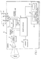
- Fig. 1 is a schematic block diagram of a camera having a transceiver employed with antenna apparatus according to the present invention;
- Fig. 2 is a front view of a camera having an antenna according to the present invention;
- Fig. 3 is a side view of the camera shown in Fig. 2;
- Fig. 4 is perspective view of one possible embodiment of an antenna array useful with the present invention; and
- Fig. 5 is a side view of a camera wherein the body of the camera is used as a reflector for the antenna array.
-
- Referring to Fig. 1, a
typical wideband transceiver 10 in adigital camera 12 useful with an antenna arrangement of the present invention is shown. As used herein, the term wideband means any RF transceiver capable of communication data rates of 10 megabits per second or faster. Thecamera 12 includes alens 14 and animage sensor 16. The overall operation of thecamera 12 is controlled by amicroprocessor 18, which receives control inputs from acontrol panel 20, displays control instructions and images on adisplay 22, and manages images stored in acamera memory 24. Thedisplay 22 andcontrol panel 20 together comprise a graphical user interface (GUI) 26. The-display 22 andcontrol panel 20 can be integrated as a touch screen. Anantenna array 27 including a pair ofdirectional antennas transceiver 10 through anantenna switch 32. - The
transceiver 10 is controlled by themicroprocessor 18 to transmit and receive digital image files and other information to and from other cameras and communication devices in the neighborhood of thecamera 12. Theantenna switch 32 is under control of themicroprocessor 18 and can switch betweendirectional antennas microprocessor 18 receives an RSSI (received signal strength indicator) signal from the transceiver and periodically switches back and forth (e.g. every few seconds) between the antennas to determine which provides the strongest RSSI signal. This provides spatial diversity to the transceiver. Alternatively, the microprocessor can monitor the rate of packet errors and switch between the antennas to minimize the packet error rate. - In one possible mode of operation, the
microprocessor 18 periodically signals theRF transceiver 10 via a frequency control line to change the carrier frequency of theRF transceiver 10, monitors a received signal strength indicator (RSSI) signal from the transceiver, and selects the carrier frequency that provides the strongest signal to the transceiver to provide frequency diversity to the wideband RF transceiver. - Referring to Fig. 2, the
camera 12 may include aflash lamp 34 and a pair ofgrips lens 14. The camera grips 36 and 38 are located on opposite sides of the camera body for holding the camera to operate the transceiver while a camera user 40 (see Fig. 3) views thegraphic user interface 26. Theantenna array 27 is located for example on one side of theflash mechanism 34 where it is not covered by a user's hands on the hand grips. - Turning now to Fig. 3, the location and direction of the
directional antenna array 27 on thecamera 12 according to the present invention will be described. Thedirectional antenna array 27 is arranged with respect to the camera to point away from a user of the camera and having a 90 ± 10 degree vertical beam width centered on the horizon ± 20 degrees, and a 180 ± 20 degree horizontal beam width when the camera is held by thegrips graphic user interface 26 while operating thetransceiver 10. - Referring to Fig. 4, one embodiment of an
antenna array 27 according to the present invention includes afirst antenna 28 having a radiatingelement 42 and a reflectingelement 44. The elements would typically be one half wavelength or less long, e.g. about 6 cm or less for the 2.45 GHz band. The radiatingelement 42 is coupled to the transceiver by a balanced to unbalanced transformer (balun) 46, and the reflectingelement 44 is connected to ground. Thesecond antenna 30 located a distance d, for example one quarter wavelength from the first antenna, includes a radiatingelement 48 coupled to the transceiver by abalun 50, and a reflectingelement 52. The first and second antennas may be constructed from discrete elements and encapsulated in a block of plastic and mounted outside the body of a metal bodied camera. Alternatively, the antenna array may be formed by printing the antenna elements on a printed circuit board and the printed circuit board mounted inside a plastic bodied camera. The antenna elements could also be formed in the body of a plastic bodied camera as shown in Fig. 5. - Fig. 5 shows a side view of the
camera 12 withlens 14 andGUI 26. Theantenna elements camera body 56. The antenna elements are connected to the antenna switch 32 (not shown) which is located on the RF transceiver Printed Circuit Board (PCB) 41. The plastic case orouter enclosure 56 of the camera is lined with a conductive surface like a conductive paint or metal film to form aFaraday cage 54 about the electronics of the digital camera. Such conductive surfaces are most always used in electronic products to prevent the emissions of electromagnetic radiation. TheFaraday cage 54 can as shown also be used as the reflector for the radiating elements to form a directional antenna array. The radiating elements could easily be modeled into the plastic outer case of the camera body. Small wires or a connector could be used to connect the radiatingelements RF transceiver PCB 41. - Alternatively, where the camera has a metal body, the
antenna elements
Claims (7)
- A digital camera having a wideband RF transceiver, comprising:a) a graphic user interface for displaying a camera control menu, the graphic user interface having a normal viewing axis;b) camera grips located on opposite sides of the camera body for holding the camera to operate the transceiver while viewing the graphic user interface; andc) a directional antenna arranged with respect to the camera to point away from a user of the camera and having a 90 ± 10 degree vertical beam width centered on the horizon ± 20 degrees, and a 180 ± 20 degree horizontal beam width when the camera is held by the grips for normal viewing of the graphic user interface while operating the transceiver.
- The digital camera claimed in claim 1, further comprising:a) a second antenna;b) an antenna switch for selectively connecting the first or second antenna to the RF transceiver; andc) a control circuit connected to the RF transceiver and the antenna switch for receiving a received signal strength indicator (RSSI) signal from the transceiver and controlling the antenna switch to connect the antenna that provides the strongest signal to the transceiver to provide spatial diversity to the RF transceiver.
- The digital camera claimed in claim 1, wherein the antenna is connected to the transceiver and located on the top of the camera adjacent the transceiver in a location where it is not covered by a user's hands on the hand grips.
- The digital camera claimed in claim 1, further comprising:means for changing the carrier frequency of the wideband RF transceiver and a received signal strength indicator (RSSI) signal from the transceiver and selecting the carrier frequency that provides the strongest signal to the transceiver to provide frequency diversity to the wideband RF transceiver.
- The digital camera claimed in claim 1 further comprising a camera body that functions as a reflector for the directional antenna.
- The digital camera claimed in claim 6, wherein the camera body is metal.
- The digital camera claimed in claim 6, wherein the camera body is plastic lined with an electrically conductive coating.
Applications Claiming Priority (2)
| Application Number | Priority Date | Filing Date | Title |
|---|---|---|---|
| US09/735,107 US6694151B2 (en) | 2000-12-12 | 2000-12-12 | Antenna apparatus for digital cameras incorporating wideband RF transceivers |
| US735107 | 2000-12-12 |
Publications (1)
| Publication Number | Publication Date |
|---|---|
| EP1215893A1 true EP1215893A1 (en) | 2002-06-19 |
Family
ID=24954388
Family Applications (1)
| Application Number | Title | Priority Date | Filing Date |
|---|---|---|---|
| EP01204629A Withdrawn EP1215893A1 (en) | 2000-12-12 | 2001-11-30 | Antenna apparatus for digital cameras incorporating wideband RF transceivers |
Country Status (3)
| Country | Link |
|---|---|
| US (1) | US6694151B2 (en) |
| EP (1) | EP1215893A1 (en) |
| JP (1) | JP2002271674A (en) |
Cited By (10)
| Publication number | Priority date | Publication date | Assignee | Title |
|---|---|---|---|---|
| EP1686651A3 (en) * | 2005-01-31 | 2006-08-30 | Fujitsu Component Limited | Antenna apparatus and electronic device |
| WO2006113250A1 (en) | 2005-04-15 | 2006-10-26 | Texas Instruments Incorporated | System and method for steering directional antenna for wireless communication |
| WO2008054903A1 (en) * | 2006-10-29 | 2008-05-08 | Sony Ericsson Mobile Communications Ab | Camera with integrated wireless interface |
| WO2008063565A2 (en) * | 2006-11-16 | 2008-05-29 | Stryker Corporation | Wireless endoscopic camera |
| CN101639700B (en) * | 2008-07-30 | 2011-08-24 | 比亚迪股份有限公司 | Tracking rotation device and shooting system |
| WO2012075161A1 (en) * | 2010-12-02 | 2012-06-07 | Apple Inc. | Methods for selecting antennas to avoid signal bus interference |
| CN102566602A (en) * | 2012-02-29 | 2012-07-11 | 天津天地伟业数码科技有限公司 | Method for promoting accuracy of preset position of dome camera |
| EP2525440A1 (en) * | 2011-05-18 | 2012-11-21 | AmTRAN Technology Co., Ltd. | Display device having directional antenna |
| CN102800248A (en) * | 2011-05-25 | 2012-11-28 | 瑞轩科技股份有限公司 | Display device with directional antenna |
| CN103996356A (en) * | 2011-05-25 | 2014-08-20 | 瑞轩科技股份有限公司 | Display device with directional antenna |
Families Citing this family (11)
| Publication number | Priority date | Publication date | Assignee | Title |
|---|---|---|---|---|
| US20040018815A1 (en) * | 2002-07-25 | 2004-01-29 | Tsung-Liang Lin | Wireless communication circuit architecture |
| JP4080316B2 (en) * | 2002-12-10 | 2008-04-23 | 富士フイルム株式会社 | Imaging device, terminal device, and imaging system |
| US7151454B2 (en) * | 2003-01-02 | 2006-12-19 | Covi Technologies | Systems and methods for location of objects |
| US7254373B2 (en) | 2003-01-28 | 2007-08-07 | Conexant, Inc. | Antenna diversity based on packet errors |
| DE112004002811T5 (en) * | 2004-03-30 | 2008-03-13 | Purdue Research Foundation, Lafayette | Improved microchannel heat sink |
| US7627296B2 (en) * | 2004-10-18 | 2009-12-01 | Research In Motion Limited | Method of controlling a plurality of internal antennas in a mobile communication device |
| EP1803233A4 (en) * | 2004-10-18 | 2009-06-17 | Research In Motion Ltd | Method of controlling a plurality of internal antennas in a mobile communication device |
| JP2007180643A (en) * | 2005-12-27 | 2007-07-12 | Sony Corp | Switching device, signal transmission circuit device, and switching method |
| KR102078299B1 (en) | 2013-04-02 | 2020-02-18 | 삼성디스플레이 주식회사 | Display appatus having anttena |
| TWI656692B (en) * | 2015-12-31 | 2019-04-11 | 鴻海精密工業股份有限公司 | Communication device |
| TWM563720U (en) * | 2018-04-10 | 2018-07-11 | 和碩聯合科技股份有限公司 | Mobile phone case |
Citations (3)
| Publication number | Priority date | Publication date | Assignee | Title |
|---|---|---|---|---|
| WO1996031051A1 (en) * | 1995-03-30 | 1996-10-03 | Polaroid Corporation | Passive transceiver for electronic still cameras |
| US5943603A (en) * | 1995-04-24 | 1999-08-24 | Eastman Kodak Company | Electronic camera system with programmable transmission capability |
| JP2000174540A (en) * | 1998-12-04 | 2000-06-23 | Sony Corp | Monopole antenna |
Family Cites Families (5)
| Publication number | Priority date | Publication date | Assignee | Title |
|---|---|---|---|---|
| US4696058A (en) | 1983-12-06 | 1987-09-22 | Matsushita Electric Industrial Co., Ltd. | Diversity receiver |
| US5625881A (en) | 1994-04-28 | 1997-04-29 | Bell-Northern Research Ltd. | Time and frequency diveristy in a radio system having intermittent operation receivers |
| US5806005A (en) | 1996-05-10 | 1998-09-08 | Ricoh Company, Ltd. | Wireless image transfer from a digital still video camera to a networked computer |
| KR100389840B1 (en) * | 2000-12-29 | 2003-07-02 | 삼성전자주식회사 | Auto-answering machine in a video phone and control method thereof |
| US20030103144A1 (en) * | 2001-12-04 | 2003-06-05 | Robert Sesek | Digital camera having image transfer method and system |
-
2000
- 2000-12-12 US US09/735,107 patent/US6694151B2/en not_active Expired - Lifetime
-
2001
- 2001-11-30 EP EP01204629A patent/EP1215893A1/en not_active Withdrawn
- 2001-12-04 JP JP2001369540A patent/JP2002271674A/en active Pending
Patent Citations (3)
| Publication number | Priority date | Publication date | Assignee | Title |
|---|---|---|---|---|
| WO1996031051A1 (en) * | 1995-03-30 | 1996-10-03 | Polaroid Corporation | Passive transceiver for electronic still cameras |
| US5943603A (en) * | 1995-04-24 | 1999-08-24 | Eastman Kodak Company | Electronic camera system with programmable transmission capability |
| JP2000174540A (en) * | 1998-12-04 | 2000-06-23 | Sony Corp | Monopole antenna |
Non-Patent Citations (4)
| Title |
|---|
| BURSKY D: "MINIATURE EMBEDDABLE ANTENNA TARGETS BLUETOOTH SYSTEMS, WEIGHS IN AT 1 G", ELECTRONIC DESIGN, PENTON PUBLISHING, CLEVELAND, OH, US, vol. 47, no. 22, 28 October 1999 (1999-10-28), pages 28, XP000928226, ISSN: 0013-4872 * |
| HASCHER W: "KABEL-KILLER BLUETOOTH GERAETEKONZEPTE UND ANWENDUNGEN", ELEKTRONIK, FRANZIS VERLAG GMBH. MUNCHEN, DE, vol. 49, no. 7, 4 April 2000 (2000-04-04), pages 62 - 65, XP000959792, ISSN: 0013-5658 * |
| PATENT ABSTRACTS OF JAPAN vol. 2000, no. 09 13 October 2000 (2000-10-13) * |
| RAY GRIMES: "The Embedded Antenna", NET CONTROL, July 2000 (2000-07-01), Orange, CA, USA, pages 4, XP002193816, Retrieved from the Internet <URL:www.ocraces.org/newsletters/netcontrol-7-00.pdf> [retrieved on 20020321] * |
Cited By (26)
| Publication number | Priority date | Publication date | Assignee | Title |
|---|---|---|---|---|
| US7339533B2 (en) | 2005-01-31 | 2008-03-04 | Fujitsu Component Limited | Antenna apparatus and electronic device |
| EP1686651A3 (en) * | 2005-01-31 | 2006-08-30 | Fujitsu Component Limited | Antenna apparatus and electronic device |
| EP1944830A1 (en) * | 2005-01-31 | 2008-07-16 | Fujitsu Component Limited | Antenna apparatus and electronic device |
| US7986272B2 (en) | 2005-01-31 | 2011-07-26 | Fujitsu Component Limited | Antenna apparatus and electronic device |
| US7495618B2 (en) | 2005-01-31 | 2009-02-24 | Fujitsu Component Limited | Antenna apparatus and electronic device |
| CN101160730B (en) * | 2005-04-15 | 2011-03-16 | 德克萨斯仪器股份有限公司 | System and method for steering directional antenna for wireless communication |
| WO2006113250A1 (en) | 2005-04-15 | 2006-10-26 | Texas Instruments Incorporated | System and method for steering directional antenna for wireless communication |
| EP1875615A1 (en) * | 2005-04-15 | 2008-01-09 | Texas Instruments Incorporated | System and method for steering directional antenna for wireless communication |
| EP1875615A4 (en) * | 2005-04-15 | 2010-01-13 | Texas Instruments Inc | System and method for steering directional antenna for wireless communication |
| WO2008054903A1 (en) * | 2006-10-29 | 2008-05-08 | Sony Ericsson Mobile Communications Ab | Camera with integrated wireless interface |
| AU2007322085B2 (en) * | 2006-11-16 | 2013-06-27 | Stryker Corporation | Wireless endoscopic camera |
| US11382488B2 (en) | 2006-11-16 | 2022-07-12 | Stryker Corporation | Wireless endoscopic camera |
| CN101541228B (en) * | 2006-11-16 | 2012-10-03 | 斯特赖克公司 | Wireless endoscopic camera |
| WO2008063565A3 (en) * | 2006-11-16 | 2008-10-30 | Stryker Corp | Wireless endoscopic camera |
| WO2008063565A2 (en) * | 2006-11-16 | 2008-05-29 | Stryker Corporation | Wireless endoscopic camera |
| US8545396B2 (en) | 2006-11-16 | 2013-10-01 | Stryker Corporation | Wireless endoscopic camera |
| US10667671B2 (en) | 2006-11-16 | 2020-06-02 | Stryker Corporation | Wireless endoscopic camera |
| CN101639700B (en) * | 2008-07-30 | 2011-08-24 | 比亚迪股份有限公司 | Tracking rotation device and shooting system |
| WO2012075161A1 (en) * | 2010-12-02 | 2012-06-07 | Apple Inc. | Methods for selecting antennas to avoid signal bus interference |
| US8577321B2 (en) | 2010-12-02 | 2013-11-05 | Apple, Inc. | Methods for selecting antennas to avoid signal bus interference |
| US9035846B2 (en) | 2011-05-18 | 2015-05-19 | Amtran Technology Co., Ltd | Display device having directional antenna |
| EP2525440A1 (en) * | 2011-05-18 | 2012-11-21 | AmTRAN Technology Co., Ltd. | Display device having directional antenna |
| CN102800248A (en) * | 2011-05-25 | 2012-11-28 | 瑞轩科技股份有限公司 | Display device with directional antenna |
| CN102800248B (en) * | 2011-05-25 | 2015-04-08 | 瑞轩科技股份有限公司 | Display device with directional antenna |
| CN103996356A (en) * | 2011-05-25 | 2014-08-20 | 瑞轩科技股份有限公司 | Display device with directional antenna |
| CN102566602A (en) * | 2012-02-29 | 2012-07-11 | 天津天地伟业数码科技有限公司 | Method for promoting accuracy of preset position of dome camera |
Also Published As
| Publication number | Publication date |
|---|---|
| US20020107052A1 (en) | 2002-08-08 |
| US6694151B2 (en) | 2004-02-17 |
| JP2002271674A (en) | 2002-09-20 |
Similar Documents
| Publication | Publication Date | Title |
|---|---|---|
| US6694151B2 (en) | Antenna apparatus for digital cameras incorporating wideband RF transceivers | |
| US7530180B2 (en) | Mobile communication handset with adaptive antenna array | |
| CN106575970B (en) | Electronic equipment with the switching of tunable antenna, adjustable antenna impedance matching circuit and antenna | |
| AU750257B2 (en) | Multiple frequency band antenna | |
| US7034759B2 (en) | Adaptive receive and omnidirectional transmit antenna array | |
| EP1481442B1 (en) | User terminal antenna arrangement for multiple-input multiple-output communications | |
| JP3112464B2 (en) | Portable wireless communication device | |
| JP2006203648A (en) | Portable radio | |
| US6882320B2 (en) | Diversity antenna apparatus for portable wireless terminal | |
| WO2012167515A1 (en) | Protective case for mobile terminal and mobile terminal | |
| GB2327572A (en) | Telephone with multiple antenna comfiguration for reduced user irradiation | |
| JP2003163956A (en) | Portable radio set | |
| CN113948860B (en) | Electronic equipment | |
| JP3751533B2 (en) | Portable wireless terminal | |
| JPH08288895A (en) | Portable communication equipment | |
| JP2000259295A (en) | Information processor | |
| JP2006050136A (en) | Mobile phone | |
| JPH06112880A (en) | Portable telephone set | |
| KR101294310B1 (en) | Mobile terminal | |
| EP1195842A1 (en) | Antenna structure of portable radio | |
| JPH08125435A (en) | Antenna for equipment for personal communication base station | |
| JP2003037411A (en) | Portable radio equipment | |
| KR20070014854A (en) | Antenna-detachable mobile communication terminal and method for attachingg/detaching planar inverted f-antenna | |
| JP2002016434A (en) | Antenna device | |
| JP2007134988A (en) | Radio terminal device, external antenna device, and antenna |
Legal Events
| Date | Code | Title | Description |
|---|---|---|---|
| PUAI | Public reference made under article 153(3) epc to a published international application that has entered the european phase |
Free format text: ORIGINAL CODE: 0009012 |
|
| AK | Designated contracting states |
Kind code of ref document: A1 Designated state(s): AT BE CH CY DE DK ES FI FR GB GR IE IT LI LU MC NL PT SE TR |
|
| AX | Request for extension of the european patent |
Free format text: AL;LT;LV;MK;RO;SI |
|
| 17P | Request for examination filed |
Effective date: 20021113 |
|
| AKX | Designation fees paid |
Designated state(s): DE FR GB |
|
| 17Q | First examination report despatched |
Effective date: 20070413 |
|
| STAA | Information on the status of an ep patent application or granted ep patent |
Free format text: STATUS: THE APPLICATION IS DEEMED TO BE WITHDRAWN |
|
| 18D | Application deemed to be withdrawn |
Effective date: 20070824 |