EP1215755A1 - Connecting structure of electrical component to electrial junction box - Google Patents
Connecting structure of electrical component to electrial junction box Download PDFInfo
- Publication number
- EP1215755A1 EP1215755A1 EP01129264A EP01129264A EP1215755A1 EP 1215755 A1 EP1215755 A1 EP 1215755A1 EP 01129264 A EP01129264 A EP 01129264A EP 01129264 A EP01129264 A EP 01129264A EP 1215755 A1 EP1215755 A1 EP 1215755A1
- Authority
- EP
- European Patent Office
- Prior art keywords
- electrical component
- junction box
- bus bar
- electrical
- terminals
- Prior art date
- Legal status (The legal status is an assumption and is not a legal conclusion. Google has not performed a legal analysis and makes no representation as to the accuracy of the status listed.)
- Withdrawn
Links
Images


Classifications
-
- H—ELECTRICITY
- H05—ELECTRIC TECHNIQUES NOT OTHERWISE PROVIDED FOR
- H05K—PRINTED CIRCUITS; CASINGS OR CONSTRUCTIONAL DETAILS OF ELECTRIC APPARATUS; MANUFACTURE OF ASSEMBLAGES OF ELECTRICAL COMPONENTS
- H05K3/00—Apparatus or processes for manufacturing printed circuits
- H05K3/30—Assembling printed circuits with electric components, e.g. with resistors
- H05K3/32—Assembling printed circuits with electric components, e.g. with resistors electrically connecting electric components or wires to printed circuits
- H05K3/328—Assembling printed circuits with electric components, e.g. with resistors electrically connecting electric components or wires to printed circuits by welding
-
- H—ELECTRICITY
- H01—ELECTRIC ELEMENTS
- H01R—ELECTRICALLY-CONDUCTIVE CONNECTIONS; STRUCTURAL ASSOCIATIONS OF A PLURALITY OF MUTUALLY-INSULATED ELECTRICAL CONNECTING ELEMENTS; COUPLING DEVICES; CURRENT COLLECTORS
- H01R9/00—Structural associations of a plurality of mutually-insulated electrical connecting elements, e.g. terminal strips or terminal blocks; Terminals or binding posts mounted upon a base or in a case; Bases therefor
- H01R9/22—Bases, e.g. strip, block, panel
- H01R9/24—Terminal blocks
- H01R9/2425—Structural association with built-in components
-
- H—ELECTRICITY
- H01—ELECTRIC ELEMENTS
- H01R—ELECTRICALLY-CONDUCTIVE CONNECTIONS; STRUCTURAL ASSOCIATIONS OF A PLURALITY OF MUTUALLY-INSULATED ELECTRICAL CONNECTING ELEMENTS; COUPLING DEVICES; CURRENT COLLECTORS
- H01R9/00—Structural associations of a plurality of mutually-insulated electrical connecting elements, e.g. terminal strips or terminal blocks; Terminals or binding posts mounted upon a base or in a case; Bases therefor
- H01R9/22—Bases, e.g. strip, block, panel
- H01R9/226—Bases, e.g. strip, block, panel comprising a plurality of conductive flat strips providing connection between wires or components
Definitions
- the present invention relates to a connecting structure of an electrical component to an electrical junction box for connecting the electrical component to a bus bar of the electrical junction box to form a circuit.
- the connecting structure has a plurality of long terminals 3 projecting from an electrical component 1, and a flat-plate like bus bar 7 provided in an electrical junction box 5 to which the electrical component 1 is connected.
- the electrical component 1 used in this connecting structure 23 comprises a relay or the like.
- the plurality of long terminals 3 are outwardly extended from the circuit provided inside.
- the electrical junction box 5 has a case 13 including a case 13 having a connecting portion 11 to which the electrical component 1 is to be connected, and a bus bar 7 accommodated in the case 13.
- a connecting portion 11 formed in the case 13 accommodates a plurality of junction terminals 15, and when the electrical component 1 is connected to the connecting portion 11, the plurality of terminals 3 are introduced into the connecting portion 11.
- the bus bar 7 is formed by stamping a conductive metal plate into a predetermined shape.
- the bus bar 7 is sandwiched between insulating plates 17 and 19 so that opposite sides of the bus bar 7 insulated.
- a plurality of tabs 21 project from predetermined positions of the bus bar 7 in accordance with a circuit design, and each tab 21 passes through the insulating plate 17.
- the tabs 21 are disposed in the connecting portion 11 of the electrical junction box 5, and are connected to one side of the junction terminals 15 in its longitudinal direction.
- the electrical junction box 5 since the junction terminals 15 is accommodated in the connecting portion 11 of the electrical junction box 5 to which the electrical component 1 is to be connected, the electrical junction box 5 must be increased in size by the size of the connecting portion 11 and the junction terminals 15, and the connecting structure 23 is increased in size and weight as a whole.
- the tabs 21 are formed by stamping developed tabs 21 together with the bus bar 7 and then, the tabs 21 are projected from the bus bar 7. Therefore, the bus bar 7 is formed by stamping the metal plate such that the tabs 21 are avoided
- a first aspect of the present invention provides a connecting structure of an electrical component to an electrical junction box, comprising a plurality of long terminals provided on the electrical component, a flat plate-like bus bar which is provided in the electrical junction box to which the electrical component is to be connected, the bus bar being brought into conduction with the terminals in a state, in which the electrical component is connected to the electrical junction box, a plurality of contact portions formed by bending tip ends of the plurality of terminals toward an outer periphery of the electrical component, the contact portions being formed on front ends of the terminals in a connecting direction of the electrical component to the electrical junction box, the contact portions being contacted with the bus bar in the state in which the electrical component is connected to the electrical junction box, and holding means for holding a contacted state between the plurality of contact portions and the bus bar.
- the contact portions of the plurality of terminals are brought into contact with the bus bar, and the contacted state between the contact portions and the bus bar is held by the holding means.
- the holding means tightly connecting the contacted portions between the contact portions and the bus bar in the state in which the electrical component is connected to the electrical junction box.
- the contacted portions of the end surfaces of the contact portions of the plurality of terminals and the outer surface of the bus bar is tightly connected by the holding means. Therefore, the bus bar and the plurality of terminals can be secured reliably.
- a third or fourth aspect of the invention in the connecting structure of an electrical component to an electrical junction box of the first or second aspect, the plurality of contact portions are formed by bending the terminals in a direction intersecting a projecting direction of the electrical component toward the electrical junction box, end surfaces formed on front ends of the terminals in the projecting direction are brought into contact with the outer surface of the bus bar in the state in which the electrical component is connected to the electrical junction box.
- the contact portions of the terminals formed in the direction intersecting the projecting direction from the electrical component bring the end surfaces formed on the front ends of the terminals into contact with the outer surface of the bus bar in the state in which the electrical component is connected to the electrical junction box.
- a connecting structure 25 of the electrical component to the electrical junction box an electrical component 29 is accommodated in an electrical junction box 27 and connected to the electrical junction box 27.
- the connecting structure 25 comprises a plurality of terminals 31 provided on the electrical component 29 and a bus bar 33 provided in the electrical junction box 27, a plurality of contact portions 35 respectively formed on the plurality of terminals 31 and contacting with the bus bar 33, and holding means 37 for keeping the contact state between the contact portions 35 and the bus bar 33.
- the electrical component 29 includes a part body 39 comprising a relay and formed with a circuit (not shown), and a plurality of terminals 31 projecting from the part body 39.
- Each of the plurality of terminals 31 comprises a long conductive metal plate.
- One ends of the terminals 31 in their longitudinal direction are connected to the circuit in the part body 39, and the other ends, i.e., tip ends of the terminals 31 outwardly project from the part body 39.
- Sizes in the longitudinal direction of portions of the plurality of terminals 31 projecting from the part body 39 are substantially the same, and a widthwise size of each the terminal 31 is set in accordance with permissible current determined by specification of the electrical component 29.
- the other end of each the terminal 31 in its longitudinal direction is bent at a predetermined position projecting from the part body 39 toward the outer peripheral side of the part body 39 in the longitudinal direction.
- One side of the terminal 31 from its bent portion is a terminal body 41, and the other side from the bent portion of the terminal 31 is the contact portion 35.
- Each of the terminal bodies 41 is formed into a rectangular plate-like shape, and projects in a connecting direction of the electrical component 29 to the electrical junction box 27 from the part body 39 by a predetermined distance.
- the terminal body 41 is provided at its front end in its projecting direction from the part body 39 with the contact portions 35.
- the contact portion 35 is formed into a rectangular plate-like shape, and is formed in a direction intersecting with the projecting direction from the terminal body 41, and the contact portions 35 is a front end of the terminal 31 in a connecting direction of the electrical component 29 to the electrical junction box 27 as a whole.
- One end of each of the contact portions 35 is integrally formed on the front end of the terminal body 41 in its projecting direction from the part body 39.
- the other side, i.e., the tip end of the terminal 31 is disposed outside the outer periphery of the part body 39.
- the end surface 49 of the contact portion 35 formed on the front end side in the projecting direction of the terminal body 41 is in contact with the outer surface 47 of the bus bar 33 in a state in which the electrical component 29 is connected to the electrical junction box 27.
- the electrical junction box 27 formed in this manner to which the electrical component 29 is connected comprises upper and lower cases coupled to each other to form a box-like shape, and a bus bar 33 accommodated in the upper and lower cases.
- the upper and lower cases are coupled to each other to form the box-like shape having a space therein.
- the upper and lower cases accommodate the electrical component 29 together with the bus bar 33.
- the bus bar 33 is a flat plate-like shape, and is formed by stamping a conductive metal plate into a predetermined shape in accordance with the circuit design.
- the bus bar 33 is superposed on a plate-like insulating plate 43, and an inner surface 45 of the bus bar 33 which is in contact with the insulating plate 43 is tightly contacted with the insulating plate 43 and electrically insulated.
- An outer surface 47 of the bus bar 33 formed on the opposite side from the inner surface 45 is brought into contact with end surfaces 49 of the plurality of contact portions 35 of the electrical component 29 when the electrical component 29 is connected to the electrical junction box 27.
- the above-described holding means 37 is formed by welding. In a state in which the electrical component 29 is connected to the electrical junction box 27, the holding means 37 tightly connects the end surfaces 49 of the plurality of contact portions 35 of the electrical component 29 and the outer surface 47 of the bus bar 33 of the electrical junction box 27 with each other.
- the holding means 37 is formed by resistance welding which welds the end surfaces 49 of the plurality of contact portions 35 and the outer surface 47 of the bus bar 33 using heat generated by electrical resistance, by ultrasonic welding which welds the end surfaces 49 of the plurality of contact portions 35 and the outer surface 47 of the bus bar 33 using heat generated by fine vibration caused by ultrasound, or by electron-beam welding which welds the end surfaces 49 of the plurality of contact portions 35 and the outer surface 47 of the bus bar 33 using heat generated by collision of electron beams.
- the holding means may be formed by laser welding using a core material for connecting the outer periphery of the contact portion 35 and the outer surface 47 of the bus bar 33.
- the holding means of the present embodiment is formed by welding, the holding means may be formed by soldering.
- the holding means of the present embodiment tightly connects the contact portion 35 and the bus bar 33, but the holding means may be formed of an accommodating portion formed into substantially the same shape as that of the part body 39 of the electrical component 29.
- the part body 39 in a state in which the electrical component 29 is connected to the electrical junction box, the part body 39 is accommodated in the accommodating portion, the part body 39 and the end surface 49 of the contact portion 35 are pressed by the inner peripheral surface of the accommodating portion and the outer surface 47 of the bus bar 33 to sandwich the electrical component 29, thereby positioning and fixing the electrical component 29 corresponding to the bus bar 33.
- the upper and lower cases of the electrical junction box 27 are previously brought into a developed state having an opening on the side of the outer surface 47 of the bus bar 33.
- the contact portions 35 of the plurality of terminals 31 of the electrical component 29 are aligned with predetermined positions of the bus bar 33 in accordance with the circuit design, and the electrical component 29 is moved toward the electrical junction box 27.
- the end surfaces 49 of the plurality of contact portions 35 of the electrical component 29 are brought into contact with the outer surface 47 of the bus bar 33, and the plurality of terminals 31 of the electrical component 29 are brought into conduction with the bus bar 33 of the electrical junction box 27.
- sizes of the contact portions 35 of the plurality of terminals 31 are set into predetermined values, and the contact portions 35 are electrically connected with the bus bar 33 stably.
- the size of the contact portion 35 is adjusted in accordance with the permissible current by changing the bending position of each of the plurality of terminals 31.
- the contact state of the plurality of terminals 31 and the bus bar 33 is held by the holding means 37.
- the end surfaces 49 of the contact portions 35 of the plurality of terminals 31 and the outer surface 47 of the bus bar 33 are welded, and the holding means 37 are formed between the end surfaces 49 of the plurality of contact portions 35 of the plurality of terminals 31 and the outer surface 47 of the bus bar 33. Therefore, the plurality of contact portions 35 and the bus bar 33 are tightly connected to each other by the holding means 37.
- the electrical component 29 is fixed on the bus bar 33, and the contacted state between the plurality of contact portions 35 and the outer surface 47 of the bus bar 33 is held.
- the electrical component 29 and the bus bar 33 constitute a circuit.
- the developed upper and lower cases are assembled, and a box-like body is formed by the upper and lower cases.
- the electrical component 29 and the bus bar 33 are surrounded by the upper and lower cases, the electrical component 29 is accommodated in the electrical junction box 27 together with the bus bar 33, and the electrical component 29 is connected to the electrical junction box 27.
- the connecting structure 25 of the electrical component to the electrical junction box of this embodiment the contact portions 35 of the plurality of terminals 31 are directly brought into contact and conduction with the bus bar 33, and the contacted state between the contact portions 35 and the bus bar 33 is held by the holding means 37. Therefore, according to this connecting structure 25, a junction terminal is not used for connecting the electrical component 29 to the electrical junction box 27 unlike the proposed art, the number of constituent parts of the electrical junction box 27 is reduced, the entire producing cost can be reduced, and it is possible to manage the parts easily.
- the connecting structure 25 of the present embodiment since the junction terminal is not used for connecting the plurality of terminals 31 of the electrical component 29 and the bus bar 33 of the electrical junction box 27, a portion for accommodating the junction terminal the junction terminal of the electrical junction box 27 is omitted.
- the junction terminal since the junction terminal is not used for connecting the plurality of terminals 31 of the electrical component 29 and the bus bar 33 of the electrical junction box 27, the junction terminal can be omitted, and the yield of the bus bar 33 can be enhanced without provided the bus bar 33 with a tab unlike the proposed art. As a result, the electrical junction box 27 can meet a complicated circuit, and the producing cost of the electrical junction box can be reduced.
- the connecting structure 25 since the junction terminal is not used for connecting the plurality of terminals 31 of the electrical component 29 and the bus bar 33 of the electrical junction box 27, an apparatus for assembling the junction terminal into the electrical junction box 27 can be omitted, and the producing equipment cost of the electrical junction box 27 can be reduced.
- bus bar 33 is not formed with the tab unlike the proposed art, an operation for rising the tab after stamping the metal plate can be omitted, and the bus bar 33 can be produced easily. Therefore, the producing cost of the connecting structure 25 can be reduced.
- the connecting structure 25 of the present embodiment the end surfaces 49 of the contact portions 35 of the plurality of terminals 31 are brought into contact with the outer surface 47 of the bus bar 33, and the contacted portions are tightly connected to each other by the holding means 37. Therefore, the bus bar 33 and the plurality of terminals 31 can be secured reliably.
- the electrical component 29 can be connected to the electrical junction box 27 strongly, and the reliability of connection between the electrical component 29 and the electrical junction box 27 is enhanced.
- the end surface 49 of the contact portion 35 formed by bending the terminal 31 in the direction intersecting the connecting direction of the electrical component 29 to the electrical junction box 27 is brought into contact with the outer surface 47 of the bus bar 33, and the terminal 31 and the bus bar 33 can be connected to each other with stable conductive state. Therefore, the size of the terminal body 39 in the projecting direction can be reduced, and the plurality of terminals 31 can be made small in the connecting direction of the electrical component 29 to the electrical junction box 27.
- the electrical component 29 can be made small in the connecting direction of the electrical component 29 to the electrical junction box 27, and the entire connecting structure 25 can be reduced in size, and when the electrical component 29 is mounted to a vehicle or the like, the space can be saved.
- the connecting structure 25 when the electrical junction box 27 is assembled, the electrical component 29 is previously accommodated in the electrical junction box 27, and the electrical component 29 is connected to the electrical junction box 27. Therefore, when the electrical junction box 27 is handled in a state in which the electrical junction box 27 is connected to the electrical component 29, it is possible to prevent inconvenience, e.g., prevent the electrical component 29 from coming out from the electrical junction box 27, and the operability when the electrical junction box 27 is mounted to a vehicle can be enhanced.
- the contact portion 31 is formed by bending the terminal 31, it is possible to easily adjust the projecting length of the terminal 31 from the part body 39. Therefore, when the plurality of terminals 31 of the electrical component 29 are connected to laminatedbus bars 33 respectively, the longitudinal size of the terminal 31 connected to the lower layered bus bar 33 can be increased so that the terminal 31 can easily be connected to the lower layered bus bar 33, and it is possible to easily meet a complicated circuit.
- the layout flexibility of the plurality of terminals 31 of the relay is enhanced, and it is possible to easily meet a complicated circuit.
- any one of the upper and lower cases may be provided with an opening, and in a state in which the electrical component 29 is connected to the electrical junction box 27, the electrical component 29 may project from the opening of the upper or lower case.
- the electrical component 29 comprises the relay in the above embodiment, but the present invention may be applied to a condenser or diode.
- bus bar 33 Although only one bus bar 33 is placed on the insulating plate 43, a plurality of bus bars 33 may be laminated while interposing a plurality of insulating plates 43 therebetween.
- the bus bar 33 does not have the tab in the above embodiment, the bus bar 33 may be formed with the tab. In this case, the tab of the bus bar 33 is connected to a terminal such as a connector connected to the electrical junction box 27.
Landscapes
- Engineering & Computer Science (AREA)
- Manufacturing & Machinery (AREA)
- Microelectronics & Electronic Packaging (AREA)
- Connection Or Junction Boxes (AREA)
- Multi-Conductor Connections (AREA)
Abstract
A connecting structure (23) of an electrical component
to an electrical junction box, comprises a plurality of long
terminals (31) provided on the electrical component (29), and
a flat plate-like bus bar (33) which is provided in the electrical
junction box (27) to which the electrical component (29) is to
be connected, the bus bar (33) being brought into conduction
with the terminals 31 in a state in which the electrical component
(29) is connected to the electrical junction box (27), a plurality
of contact portions (35) formed by bending tip ends of the
plurality of terminals (31) toward an outer periphery of the
electrical component (29), the contact portions (35) being formed
on front ends of the terminals (31) in a connecting direction
of the electrical component (29) to the electrical junction box
(27), the contact portions (35) being contacted With the bus
bar (33) in the state in which the electrical component (29)
is connected to the electrical junction box (27), and welding
(37) for holding a contacted state between the plurality of
contact portions (35) and the bus bar (33).
Description
- The present invention relates to a connecting structure of an electrical component to an electrical junction box for connecting the electrical component to a bus bar of the electrical junction box to form a circuit.
- There is a proposed connecting structure of an electrical component to an electrical junction box as shown in Figs. 1 to 3. The connecting structure has a plurality of
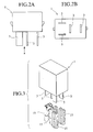
long terminals 3 projecting from anelectrical component 1, and a flat-plate like bus bar 7 provided in anelectrical junction box 5 to which theelectrical component 1 is connected. Theelectrical component 1 used in this connectingstructure 23 comprises a relay or the like. As shown in Figs. 1, 2A and 2B, the plurality oflong terminals 3 are outwardly extended from the circuit provided inside. - The
electrical junction box 5 has acase 13 including acase 13 having a connectingportion 11 to which theelectrical component 1 is to be connected, and a bus bar 7 accommodated in thecase 13. A connectingportion 11 formed in thecase 13 accommodates a plurality ofjunction terminals 15, and when theelectrical component 1 is connected to the connectingportion 11, the plurality ofterminals 3 are introduced into the connectingportion 11. - The bus bar 7 is formed by stamping a conductive metal plate into a predetermined shape. The bus bar 7 is sandwiched between
insulating plates tabs 21 project from predetermined positions of the bus bar 7 in accordance with a circuit design, and eachtab 21 passes through theinsulating plate 17. Thetabs 21 are disposed in the connectingportion 11 of theelectrical junction box 5, and are connected to one side of thejunction terminals 15 in its longitudinal direction. - In the case of the above-described connecting
structure 23, as shown in Fig. 1, when theelectrical component 1 and theelectrical junction box 5 are connected to each other, theelectrical component 1 is connected to the connectingportion 11 of theelectrical junction box 5. At that time, in theelectrical component 1 as shown in Fig. 3, the plurality ofterminals 3 are introduced into the connecting portion 11 (not shown), the plurality ofterminals 3 are respectively connected to the other ends of the plurality ofjunction terminals 15 accommodated in the connectingportion 11 in the longitudinal direction. As a result, in this connectingstructure 23, theterminals 3 of theelectrical component 1 and the bus bar 7 of theelectrical junction box 5 are brought into conduction with each other through thejunction terminals 15. - However, according to the proposed connecting
structure 23 of the electrical component to the electrical junction box, when theelectrical component 1 is connected to theelectrical junction box 5, theterminals 3 of theelectrical component 1 and thetabs 21 of the bus bar 7 of theelectrical junction box 5 are connected to each other through thejunction terminals 15. Therefore, the number of parts of the connectingstructure 23 is increased, and the producing cost thereof is also increased. - Further, in the
connecting structure 23, since thejunction terminals 15 is accommodated in the connectingportion 11 of theelectrical junction box 5 to which theelectrical component 1 is to be connected, theelectrical junction box 5 must be increased in size by the size of the connectingportion 11 and thejunction terminals 15, and the connectingstructure 23 is increased in size and weight as a whole. - Further, when the bus bar 7 is formed, the
tabs 21 are formed by stamping developedtabs 21 together with the bus bar 7 and then, thetabs 21 are projected from the bus bar 7. Therefore, the bus bar 7 is formed by stamping the metal plate such that thetabs 21 are avoided - Thus, in the connecting
structure 23, the yield of the bus bar 7 is deteriorated, and the producing cost is increased. - Thereupon, it is an object of the present invention to provide a connecting structure of an electrical component to an electrical junction box, capable of reducing the producing cost and reducing both size and weight.
- To achieve the above object, a first aspect of the present invention provides a connecting structure of an electrical component to an electrical junction box, comprising a plurality of long terminals provided on the electrical component, a flat plate-like bus bar which is provided in the electrical junction box to which the electrical component is to be connected, the bus bar being brought into conduction with the terminals in a state, in which the electrical component is connected to the electrical junction box, a plurality of contact portions formed by bending tip ends of the plurality of terminals toward an outer periphery of the electrical component, the contact portions being formed on front ends of the terminals in a connecting direction of the electrical component to the electrical junction box, the contact portions being contacted with the bus bar in the state in which the electrical component is connected to the electrical junction box, and holding means for holding a contacted state between the plurality of contact portions and the bus bar.
- According to this first aspect, when the electrical component is connected to the electrical junction box, the contact portions of the plurality of terminals are brought into contact with the bus bar, and the contacted state between the contact portions and the bus bar is held by the holding means.
- According to a second aspect of the invention, in the connecting structure of an electrical component to an electrical junction box of the first aspect, the holding means tightly connecting the contacted portions between the contact portions and the bus bar in the state in which the electrical component is connected to the electrical junction box.
- With the second aspect, in the state in which the electrical component is connected to the electrical junction box, the contacted portions of the end surfaces of the contact portions of the plurality of terminals and the outer surface of the bus bar is tightly connected by the holding means. Therefore, the bus bar and the plurality of terminals can be secured reliably.
- A third or fourth aspect of the invention, in the connecting structure of an electrical component to an electrical junction box of the first or second aspect, the plurality of contact portions are formed by bending the terminals in a direction intersecting a projecting direction of the electrical component toward the electrical junction box, end surfaces formed on front ends of the terminals in the projecting direction are brought into contact with the outer surface of the bus bar in the state in which the electrical component is connected to the electrical junction box.
- With the third or fourth aspect, the contact portions of the terminals formed in the direction intersecting the projecting direction from the electrical component bring the end surfaces formed on the front ends of the terminals into contact with the outer surface of the bus bar in the state in which the electrical component is connected to the electrical junction box.
-
- Fig. 1 is a sectional view showing a proposed connecting structure of an electrical component to an electrical junction box;
- Fig. 2A is a front view of the electrical component shown in Fig. 1, and Fig. 2B is a plan view of Fig. 2A as viewed form an arrow a in Fig. 2A;
- Fig. 3 is a perspective view when junction terminals and electrical component are connected to each other shown in Fig. 1;
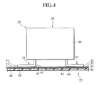
- Fig. 4 is a sectional view showing a connecting structure of an electrical component to an electrical junction box according to the present invention;
- Fig. 5 is a front view of the electrical component shown in Fig. 4;
- Fig. 6 is a plan view of the electrical component shown in Fig. 4; and
- Fig. 7 is a plan view of another electrical component used for the connecting structure of the electrical component to the electrical junction box according to the present invention.
-
- An embodiment of a connecting structure of an electrical component to an electrical junction box of the present invention will be explained below.
- As shown in Fig. 4, in a
connecting structure 25 of the electrical component to the electrical junction box, anelectrical component 29 is accommodated in anelectrical junction box 27 and connected to theelectrical junction box 27. The connectingstructure 25 comprises a plurality ofterminals 31 provided on theelectrical component 29 and abus bar 33 provided in theelectrical junction box 27, a plurality ofcontact portions 35 respectively formed on the plurality ofterminals 31 and contacting with thebus bar 33, andholding means 37 for keeping the contact state between thecontact portions 35 and thebus bar 33. - As shown in Figs. 4 and 5, the
electrical component 29 includes apart body 39 comprising a relay and formed with a circuit (not shown), and a plurality ofterminals 31 projecting from thepart body 39. - Each of the plurality of
terminals 31 comprises a long conductive metal plate. One ends of theterminals 31 in their longitudinal direction are connected to the circuit in thepart body 39, and the other ends, i.e., tip ends of theterminals 31 outwardly project from thepart body 39. Sizes in the longitudinal direction of portions of the plurality ofterminals 31 projecting from thepart body 39 are substantially the same, and a widthwise size of each theterminal 31 is set in accordance with permissible current determined by specification of theelectrical component 29. The other end of each theterminal 31 in its longitudinal direction is bent at a predetermined position projecting from thepart body 39 toward the outer peripheral side of thepart body 39 in the longitudinal direction. One side of theterminal 31 from its bent portion is aterminal body 41, and the other side from the bent portion of theterminal 31 is thecontact portion 35. - Each of the
terminal bodies 41 is formed into a rectangular plate-like shape, and projects in a connecting direction of theelectrical component 29 to theelectrical junction box 27 from thepart body 39 by a predetermined distance. Theterminal body 41 is provided at its front end in its projecting direction from thepart body 39 with thecontact portions 35. - The
contact portion 35 is formed into a rectangular plate-like shape, and is formed in a direction intersecting with the projecting direction from theterminal body 41, and thecontact portions 35 is a front end of theterminal 31 in a connecting direction of theelectrical component 29 to theelectrical junction box 27 as a whole. One end of each of thecontact portions 35 is integrally formed on the front end of theterminal body 41 in its projecting direction from thepart body 39. As shown in Fig. 3, the other side, i.e., the tip end of theterminal 31 is disposed outside the outer periphery of thepart body 39. Theend surface 49 of thecontact portion 35 formed on the front end side in the projecting direction of theterminal body 41 is in contact with theouter surface 47 of thebus bar 33 in a state in which theelectrical component 29 is connected to theelectrical junction box 27. - As shown in Fig. 7, in the
electrical component 29, the bending directions of the plurality ofterminals 31 are changed, and the positions of the other sides of thecontact portions 35 in their longitudinal direction are appropriately changed depending upon the circuit design. - The
electrical junction box 27 formed in this manner to which theelectrical component 29 is connected comprises upper and lower cases coupled to each other to form a box-like shape, and abus bar 33 accommodated in the upper and lower cases. The upper and lower cases are coupled to each other to form the box-like shape having a space therein. In a state in which theelectrical component 29 is connected to theelectrical junction box 27, the upper and lower cases accommodate theelectrical component 29 together with thebus bar 33. - As shown in Fig. 4, the
bus bar 33 is a flat plate-like shape, and is formed by stamping a conductive metal plate into a predetermined shape in accordance with the circuit design. Thebus bar 33 is superposed on a plate-like insulatingplate 43, and aninner surface 45 of thebus bar 33 which is in contact with the insulatingplate 43 is tightly contacted with the insulatingplate 43 and electrically insulated. Anouter surface 47 of thebus bar 33 formed on the opposite side from theinner surface 45 is brought into contact withend surfaces 49 of the plurality ofcontact portions 35 of theelectrical component 29 when theelectrical component 29 is connected to theelectrical junction box 27. - The above-described holding means 37 is formed by welding. In a state in which the
electrical component 29 is connected to theelectrical junction box 27, the holding means 37 tightly connects the end surfaces 49 of the plurality ofcontact portions 35 of theelectrical component 29 and theouter surface 47 of thebus bar 33 of theelectrical junction box 27 with each other. In this case, the holding means 37 is formed by resistance welding which welds the end surfaces 49 of the plurality ofcontact portions 35 and theouter surface 47 of thebus bar 33 using heat generated by electrical resistance, by ultrasonic welding which welds the end surfaces 49 of the plurality ofcontact portions 35 and theouter surface 47 of thebus bar 33 using heat generated by fine vibration caused by ultrasound, or by electron-beam welding which welds the end surfaces 49 of the plurality ofcontact portions 35 and theouter surface 47 of thebus bar 33 using heat generated by collision of electron beams. - The holding means may be formed by laser welding using a core material for connecting the outer periphery of the
contact portion 35 and theouter surface 47 of thebus bar 33. Although the holding means of the present embodiment is formed by welding, the holding means may be formed by soldering. - The holding means of the present embodiment tightly connects the
contact portion 35 and thebus bar 33, but the holding means may be formed of an accommodating portion formed into substantially the same shape as that of thepart body 39 of theelectrical component 29. In this case, in a state in which theelectrical component 29 is connected to the electrical junction box, thepart body 39 is accommodated in the accommodating portion, thepart body 39 and theend surface 49 of thecontact portion 35 are pressed by the inner peripheral surface of the accommodating portion and theouter surface 47 of thebus bar 33 to sandwich theelectrical component 29, thereby positioning and fixing theelectrical component 29 corresponding to thebus bar 33. - In the connecting
structure 25 of the electrical component to the electrical junction box constructed as described above, as shown in Fig. 4, when theelectrical component 29 is connected to theelectrical junction box 27, thecontact portions 35 of the plurality ofterminals 31 of theelectrical component 29 are first brought into contact with thebus bar 33 of theelectrical junction box 27. Then, the contact state between thecontact portions 35 of the plurality ofterminals 31 and thebus bar 33 is held by the holding means 37. Thereafter, theelectrical component 29 is accommodated into theelectrical junction box 27 together with thebus bar 33. - When the
contact portions 35 of theterminals 31 of theelectrical component 29 and thebus bar 33 in theelectrical junction box 27 are brought into contact with each other, the upper and lower cases of theelectrical junction box 27 are previously brought into a developed state having an opening on the side of theouter surface 47 of thebus bar 33. In this state, thecontact portions 35 of the plurality ofterminals 31 of theelectrical component 29 are aligned with predetermined positions of thebus bar 33 in accordance with the circuit design, and theelectrical component 29 is moved toward theelectrical junction box 27. - If the
electrical component 29 is moved toward theelectrical junction box 27, the end surfaces 49 of the plurality ofcontact portions 35 of theelectrical component 29 are brought into contact with theouter surface 47 of thebus bar 33, and the plurality ofterminals 31 of theelectrical component 29 are brought into conduction with thebus bar 33 of theelectrical junction box 27. At that time, sizes of thecontact portions 35 of the plurality ofterminals 31 are set into predetermined values, and thecontact portions 35 are electrically connected with thebus bar 33 stably. The size of thecontact portion 35 is adjusted in accordance with the permissible current by changing the bending position of each of the plurality ofterminals 31. The contact state of the plurality ofterminals 31 and thebus bar 33 is held by the holding means 37. - When the contact state of the
contact portion 35 of the plurality ofterminals 31 and thebus bar 33 is held by the holding means 37, portions between the contacted plurality ofcontact portions 35 and thebus bar 33 are welded. At that time, theelectrical component 29 is pressed toward thebus bar 33 to bring theend surface 49 of thecontact portion 35 and theouter surface 47 into contact with each other under pressure. In this state, the contacted portions between the end surfaces 49 of thecontact portions 35 of the plurality ofterminals 31 and theouter surface 47 of thebus bar 33 are heated. - As a result, the end surfaces 49 of the
contact portions 35 of the plurality ofterminals 31 and theouter surface 47 of thebus bar 33 are welded, and the holding means 37 are formed between the end surfaces 49 of the plurality ofcontact portions 35 of the plurality ofterminals 31 and theouter surface 47 of thebus bar 33. Therefore, the plurality ofcontact portions 35 and thebus bar 33 are tightly connected to each other by the holding means 37. - In a state in which the plurality of
contact portions 35 and thebus bar 33 are tightly connected to each other by the holding means 37, theelectrical component 29 is fixed on thebus bar 33, and the contacted state between the plurality ofcontact portions 35 and theouter surface 47 of thebus bar 33 is held. Thus, theelectrical component 29 and thebus bar 33 constitute a circuit. - The developed upper and lower cases are assembled, and a box-like body is formed by the upper and lower cases. In this state, the
electrical component 29 and thebus bar 33 are surrounded by the upper and lower cases, theelectrical component 29 is accommodated in theelectrical junction box 27 together with thebus bar 33, and theelectrical component 29 is connected to theelectrical junction box 27. - According to the connecting
structure 25 of the electrical component to the electrical junction box of this embodiment, thecontact portions 35 of the plurality ofterminals 31 are directly brought into contact and conduction with thebus bar 33, and the contacted state between thecontact portions 35 and thebus bar 33 is held by the holding means 37. Therefore, according to this connectingstructure 25, a junction terminal is not used for connecting theelectrical component 29 to theelectrical junction box 27 unlike the proposed art, the number of constituent parts of theelectrical junction box 27 is reduced, the entire producing cost can be reduced, and it is possible to manage the parts easily. - According to the connecting
structure 25 of the present embodiment, since the junction terminal is not used for connecting the plurality ofterminals 31 of theelectrical component 29 and thebus bar 33 of theelectrical junction box 27, a portion for accommodating the junction terminal the junction terminal of theelectrical junction box 27 is omitted. - Therefore, it is possible to reduce the size of the
electrical component 29 into the connecting direction to theelectrical junction box 27 by the sizes of the junction terminal and the portion for accommodating the junction terminal, and the amount of resin of theelectrical junction box 27 can be reduced correspondingly to lower the cost, and the entire weight can also be reduced. - Further, according to this connecting
structure 25, since the junction terminal is not used for connecting the plurality ofterminals 31 of theelectrical component 29 and thebus bar 33 of theelectrical junction box 27, the junction terminal can be omitted, and the yield of thebus bar 33 can be enhanced without provided thebus bar 33 with a tab unlike the proposed art. As a result, theelectrical junction box 27 can meet a complicated circuit, and the producing cost of the electrical junction box can be reduced. - According to the connecting
structure 25, since the junction terminal is not used for connecting the plurality ofterminals 31 of theelectrical component 29 and thebus bar 33 of theelectrical junction box 27, an apparatus for assembling the junction terminal into theelectrical junction box 27 can be omitted, and the producing equipment cost of theelectrical junction box 27 can be reduced. - Further, since the
bus bar 33 is not formed with the tab unlike the proposed art, an operation for rising the tab after stamping the metal plate can be omitted, and thebus bar 33 can be produced easily. Therefore, the producing cost of the connectingstructure 25 can be reduced. - In the connecting
structure 25 of the present embodiment, the end surfaces 49 of thecontact portions 35 of the plurality ofterminals 31 are brought into contact with theouter surface 47 of thebus bar 33, and the contacted portions are tightly connected to each other by the holding means 37. Therefore, thebus bar 33 and the plurality ofterminals 31 can be secured reliably. Thus, according to this connectingstructure 25, theelectrical component 29 can be connected to theelectrical junction box 27 strongly, and the reliability of connection between theelectrical component 29 and theelectrical junction box 27 is enhanced. - In the connecting
structure 25 of the present embodiment, theend surface 49 of thecontact portion 35 formed by bending the terminal 31 in the direction intersecting the connecting direction of theelectrical component 29 to theelectrical junction box 27 is brought into contact with theouter surface 47 of thebus bar 33, and the terminal 31 and thebus bar 33 can be connected to each other with stable conductive state. Therefore, the size of theterminal body 39 in the projecting direction can be reduced, and the plurality ofterminals 31 can be made small in the connecting direction of theelectrical component 29 to theelectrical junction box 27. - Therefore, in this connecting
structure 25, theelectrical component 29 can be made small in the connecting direction of theelectrical component 29 to theelectrical junction box 27, and the entire connectingstructure 25 can be reduced in size, and when theelectrical component 29 is mounted to a vehicle or the like, the space can be saved. - According to the connecting
structure 25, when theelectrical junction box 27 is assembled, theelectrical component 29 is previously accommodated in theelectrical junction box 27, and theelectrical component 29 is connected to theelectrical junction box 27. Therefore, when theelectrical junction box 27 is handled in a state in which theelectrical junction box 27 is connected to theelectrical component 29, it is possible to prevent inconvenience, e.g., prevent theelectrical component 29 from coming out from theelectrical junction box 27, and the operability when theelectrical junction box 27 is mounted to a vehicle can be enhanced. - In the connecting
structure 25 of the present embodiment, since thecontact portion 31 is formed by bending the terminal 31, it is possible to easily adjust the projecting length of the terminal 31 from thepart body 39. Therefore, when the plurality ofterminals 31 of theelectrical component 29 are connected to laminatedbusbars 33 respectively, the longitudinal size of the terminal 31 connected to the lower layeredbus bar 33 can be increased so that the terminal 31 can easily be connected to the lower layeredbus bar 33, and it is possible to easily meet a complicated circuit. - In the connecting
structure 25, the layout flexibility of the plurality ofterminals 31 of the relay is enhanced, and it is possible to easily meet a complicated circuit. - Although the
electrical component 29 is surrounded by the upper and lower cases together with thebus bar 33 in the state in which theelectrical component 29 is connected to theelectrical junction box 27 in the above embodiment, any one of the upper and lower cases may be provided with an opening, and in a state in which theelectrical component 29 is connected to theelectrical junction box 27, theelectrical component 29 may project from the opening of the upper or lower case. - The
electrical component 29 comprises the relay in the above embodiment, but the present invention may be applied to a condenser or diode. - Although only one
bus bar 33 is placed on the insulatingplate 43, a plurality of bus bars 33 may be laminated while interposing a plurality of insulatingplates 43 therebetween. - Although the
bus bar 33 does not have the tab in the above embodiment, thebus bar 33 may be formed with the tab. In this case, the tab of thebus bar 33 is connected to a terminal such as a connector connected to theelectrical junction box 27.
Claims (4)
- A connecting structure of an electrical component to an electrical junction box, comprising:a plurality of long terminals provided on the electrical component;a flat plate-like bus bar which is provided in the electrical junction box to which the electrical component is to be connected, the bus bar being brought into conduction with the terminals in a state in which the electrical component is connected to the electrical junction box;a plurality of contact portions formed by bending tip ends of the plurality of terminals toward an outer periphery of the electrical component, the contact portions being formed on front ends of the terminals in a connecting direction of the electrical component to the electrical junction box, the contact portions being contacted with the bus bar in the state in which the electrical component is connected to the electrical junction box; andholding means for holding a contacted state between the plurality of contact portions and the bus bar.
- A connecting structure of an electrical component to an electrical junction box according to claim 1, wherein
the holding means tightly connecting the contacted portions between the contact portions and the bus bar in the state in which the electrical component is connected to the electrical junction box. - A connecting structure of an electrical component to an electrical junction box according to claim 1, wherein
the plurality of contact portions are formed by bending the terminals in a direction intersecting a projecting direction of the electrical component toward the electrical junction box, end surfaces formed on front ends of the terminals in the projecting direction are brought into contact with the outer surface of the bus bar in the state in which the electrical component is connected to the electrical junction box. - A connecting structure of an electrical component to an electrical junction box according to claim 2, wherein
the plurality of contact portions are formed by bending the terminals in a direction intersecting a projecting direction of the electrical component toward the electrical junction box, end surfaces formed on front ends of the terminals in the projecting direction are brought into contact with the outer surface of the bus bar in the state in which the electrical component is connected to the electrical junction box.
Applications Claiming Priority (2)
| Application Number | Priority Date | Filing Date | Title |
|---|---|---|---|
| JP2000380232 | 2000-12-14 | ||
| JP2000380232A JP2002186137A (en) | 2000-12-14 | 2000-12-14 | Connection structure of electrical components to electrical junction box |
Publications (1)
| Publication Number | Publication Date |
|---|---|
| EP1215755A1 true EP1215755A1 (en) | 2002-06-19 |
Family
ID=18848457
Family Applications (1)
| Application Number | Title | Priority Date | Filing Date |
|---|---|---|---|
| EP01129264A Withdrawn EP1215755A1 (en) | 2000-12-14 | 2001-12-12 | Connecting structure of electrical component to electrial junction box |
Country Status (3)
| Country | Link |
|---|---|
| US (1) | US6619967B2 (en) |
| EP (1) | EP1215755A1 (en) |
| JP (1) | JP2002186137A (en) |
Cited By (1)
| Publication number | Priority date | Publication date | Assignee | Title |
|---|---|---|---|---|
| EP1530411A1 (en) * | 2003-11-05 | 2005-05-11 | Sumitomo Wiring Systems, Ltd. | Circuit assembly, producing method of the same, distribution unit and bus bar substrate |
Families Citing this family (8)
| Publication number | Priority date | Publication date | Assignee | Title |
|---|---|---|---|---|
| JP4022440B2 (en) * | 2002-07-01 | 2007-12-19 | 株式会社オートネットワーク技術研究所 | Circuit unit |
| JP2004096917A (en) * | 2002-09-02 | 2004-03-25 | Sumitomo Wiring Syst Ltd | Connecting structure of bus bar to relay terminal |
| JP2004104946A (en) * | 2002-09-11 | 2004-04-02 | Sumitomo Wiring Syst Ltd | Bus bar |
| JP2004249883A (en) * | 2003-02-21 | 2004-09-09 | Honda Motor Co Ltd | Automotive electronic control unit |
| DE102006018425A1 (en) * | 2006-04-20 | 2007-10-25 | BSH Bosch und Siemens Hausgeräte GmbH | Telescopic extension for a refrigeration device |
| JP4600494B2 (en) * | 2008-03-04 | 2010-12-15 | 住友電装株式会社 | Busbar substrate and method for manufacturing circuit structure |
| GB2511569B (en) * | 2013-03-08 | 2015-05-06 | Christopher John Stanton | Improved switch and associated methods |
| JP6078410B2 (en) * | 2013-04-12 | 2017-02-08 | 矢崎総業株式会社 | Assembly structure of electronic parts and electronic parts |
Citations (4)
| Publication number | Priority date | Publication date | Assignee | Title |
|---|---|---|---|---|
| US5928035A (en) * | 1997-08-22 | 1999-07-27 | Otto Dunkel Gmbh Fur Elektrotechnische Gerate | Printed circuit board socket |
| US6102748A (en) * | 1998-12-24 | 2000-08-15 | Hon Hai Precision Ind. Co., Ltd. | High density electrical connector and method of manufacturing the same |
| US6116494A (en) * | 1998-09-01 | 2000-09-12 | Hewlett-Packard Company | Method for re-attachment of a SMT component using a heated air jet |
| EP1037312A1 (en) * | 1999-03-11 | 2000-09-20 | Harness System Technologies Research, Ltd. | Circuit connection structure for a junction block |
Family Cites Families (5)
| Publication number | Priority date | Publication date | Assignee | Title |
|---|---|---|---|---|
| JPH01140580A (en) * | 1987-11-25 | 1989-06-01 | Mitsubishi Electric Corp | Connection jumper and manufacture thereof |
| US5241134A (en) * | 1990-09-17 | 1993-08-31 | Yoo Clarence S | Terminals of surface mount components |
| JPH05299003A (en) * | 1992-04-23 | 1993-11-12 | Yazaki Corp | Fusible link |
| GB2276762B (en) * | 1993-04-01 | 1996-10-30 | Plessey Semiconductors Ltd | Mounting arrangement for semiconductor devices |
| JP3495939B2 (en) * | 1999-02-26 | 2004-02-09 | 矢崎総業株式会社 | Electrical junction box |
-
2000
- 2000-12-14 JP JP2000380232A patent/JP2002186137A/en active Pending
-
2001
- 2001-12-06 US US10/003,111 patent/US6619967B2/en not_active Expired - Fee Related
- 2001-12-12 EP EP01129264A patent/EP1215755A1/en not_active Withdrawn
Patent Citations (4)
| Publication number | Priority date | Publication date | Assignee | Title |
|---|---|---|---|---|
| US5928035A (en) * | 1997-08-22 | 1999-07-27 | Otto Dunkel Gmbh Fur Elektrotechnische Gerate | Printed circuit board socket |
| US6116494A (en) * | 1998-09-01 | 2000-09-12 | Hewlett-Packard Company | Method for re-attachment of a SMT component using a heated air jet |
| US6102748A (en) * | 1998-12-24 | 2000-08-15 | Hon Hai Precision Ind. Co., Ltd. | High density electrical connector and method of manufacturing the same |
| EP1037312A1 (en) * | 1999-03-11 | 2000-09-20 | Harness System Technologies Research, Ltd. | Circuit connection structure for a junction block |
Cited By (1)
| Publication number | Priority date | Publication date | Assignee | Title |
|---|---|---|---|---|
| EP1530411A1 (en) * | 2003-11-05 | 2005-05-11 | Sumitomo Wiring Systems, Ltd. | Circuit assembly, producing method of the same, distribution unit and bus bar substrate |
Also Published As
| Publication number | Publication date |
|---|---|
| US6619967B2 (en) | 2003-09-16 |
| JP2002186137A (en) | 2002-06-28 |
| US20020076955A1 (en) | 2002-06-20 |
Similar Documents
| Publication | Publication Date | Title |
|---|---|---|
| EP0380113B1 (en) | Molded electrical connector and method for manufacturing same | |
| US7193841B2 (en) | Circuit assembly and heat-insulating member for circuit assembly | |
| JP2002058133A (en) | Junction box and assembling method therefor | |
| US20050094356A1 (en) | Circuit assembly, producing method of the same, distribution unit and bus bar substrate | |
| US6619967B2 (en) | Connecting structure of electrical component to electrical junction box | |
| US6824398B2 (en) | Structure and method for connecting bus bars in electric junction box | |
| EP0727851B1 (en) | Electrical connection construction between electrical connection box and electronic circuit unit | |
| JP2024037492A (en) | electrical junction box | |
| US20080308292A1 (en) | U-turn bus bar | |
| JP2002044831A (en) | Junction box | |
| JP2004253167A (en) | Ground terminal | |
| JP3307340B2 (en) | Circuit board and electrical junction box containing the circuit board | |
| JP4805729B2 (en) | Fixing method between terminal fittings and terminal fittings | |
| JP2024117464A (en) | Transformer and method for manufacturing the same | |
| JP2003032840A (en) | Electrical junction box | |
| JP3325221B2 (en) | Laser welding structure of bus bar | |
| JP3678138B2 (en) | Junction box | |
| JP2005269867A (en) | Circuit structure and electrical junction box | |
| JP3506101B2 (en) | Junction box internal circuit and relay connection structure | |
| US12610485B2 (en) | Electric device | |
| JP3501096B2 (en) | Junction box internal circuit and relay connection structure | |
| US20250385503A1 (en) | Wiring module | |
| JP3303801B2 (en) | Circuit board, electrical junction box provided with the circuit board, and method of manufacturing circuit board | |
| JP2001275229A (en) | Electric junction box | |
| JP2604523Y2 (en) | Electrical junction box |
Legal Events
| Date | Code | Title | Description |
|---|---|---|---|
| PUAI | Public reference made under article 153(3) epc to a published international application that has entered the european phase |
Free format text: ORIGINAL CODE: 0009012 |
|
| 17P | Request for examination filed |
Effective date: 20011212 |
|
| AK | Designated contracting states |
Kind code of ref document: A1 Designated state(s): AT BE CH CY DE DK ES FI FR GB GR IE IT LI LU MC NL PT SE TR |
|
| AX | Request for extension of the european patent |
Free format text: AL;LT;LV;MK;RO;SI |
|
| AKX | Designation fees paid |
Designated state(s): DE FR GB |
|
| RAP1 | Party data changed (applicant data changed or rights of an application transferred) |
Owner name: YAZAKI CORPORATION |
|
| STAA | Information on the status of an ep patent application or granted ep patent |
Free format text: STATUS: THE APPLICATION HAS BEEN WITHDRAWN |
|
| 18W | Application withdrawn |
Effective date: 20090223 |