EP1215558A2 - Method and circuit for calculating multiple of unit value and generating a periodic function - Google Patents
Method and circuit for calculating multiple of unit value and generating a periodic function Download PDFInfo
- Publication number
- EP1215558A2 EP1215558A2 EP01129723A EP01129723A EP1215558A2 EP 1215558 A2 EP1215558 A2 EP 1215558A2 EP 01129723 A EP01129723 A EP 01129723A EP 01129723 A EP01129723 A EP 01129723A EP 1215558 A2 EP1215558 A2 EP 1215558A2
- Authority
- EP
- European Patent Office
- Prior art keywords
- value
- modifying
- circuit
- adder
- accumulator
- Prior art date
- Legal status (The legal status is an assumption and is not a legal conclusion. Google has not performed a legal analysis and makes no representation as to the accuracy of the status listed.)
- Withdrawn
Links
Images




Classifications
-
- G—PHYSICS
- G06—COMPUTING OR CALCULATING; COUNTING
- G06F—ELECTRIC DIGITAL DATA PROCESSING
- G06F7/00—Methods or arrangements for processing data by operating upon the order or content of the data handled
- G06F7/60—Methods or arrangements for performing computations using a digital non-denominational number representation, i.e. number representation without radix; Computing devices using combinations of denominational and non-denominational quantity representations, e.g. using difunction pulse trains, STEELE computers, phase computers
- G06F7/68—Methods or arrangements for performing computations using a digital non-denominational number representation, i.e. number representation without radix; Computing devices using combinations of denominational and non-denominational quantity representations, e.g. using difunction pulse trains, STEELE computers, phase computers using pulse rate multipliers or dividers pulse rate multipliers or dividers per se
-
- G—PHYSICS
- G06—COMPUTING OR CALCULATING; COUNTING
- G06F—ELECTRIC DIGITAL DATA PROCESSING
- G06F1/00—Details not covered by groups G06F3/00 - G06F13/00 and G06F21/00
- G06F1/02—Digital function generators
- G06F1/03—Digital function generators working, at least partly, by table look-up
- G06F1/0321—Waveform generators, i.e. devices for generating periodical functions of time, e.g. direct digital synthesizers
- G06F1/0328—Waveform generators, i.e. devices for generating periodical functions of time, e.g. direct digital synthesizers in which the phase increment is adjustable, e.g. by using an adder-accumulator
Definitions
- This invention relates to a technique for generating a periodic function based on digital signals and, in particular, to a technique for generating a periodic function with reference to a function table.
- Such techniques are being used in the fields of, for example, audio, video, or communication signals processing.
- a unit angle stored in a register is repeatedly added in order to calculate a multiple of the unit angle and the amplitude of a periodic function corresponding to the multiple is referred to a function table.
- a unit angle U which is added to a multiple of the unit angle generated at previous clock, is stored in a register.
- the unit angle U is added to a multiple S 1 of the unit angle U currently stored in an accumulator by an adder.
- an amplitude corresponding to the updated multiple S 2 is referred to a function table previously stored in a function table ROM.
- the periodic function generating circuit when the unit angle U is a mixed number, namely the sum of an integer and a fraction, each fraction of the multiples S 1 , S 2 , ⁇ , S n is dropped. Consequently, error of the multiple S n gradually stacks up and increases. Furthermore, a repeating decimal is unavailable for the unit angle U because of its indefinite digits. If it is intended to set the sum of an integer and a repeating decimal as the unit angle U , the sum of the integer and an approximate value of the fraction is actually set as the unit angle U . In this case, the multiple S n includes an inevitable margin of error. This error is independent of the calculating accuracy of the adder.
- phase difference As shown in Fig. 3, stacking of errors of the multiple S n causes phase difference between theoretical and output waveforms.
- the theoretical waveform drawn as a dotted line shows calculated one in theory.
- the output waveform drawn as a solid line shows one actually output from the periodic function generating circuit. It is noted that, as time passes, the phase difference stacks up and increases.
- the accumulator may be reset.
- a permitted limit of the phase difference is predetermined.
- the accumulator is reset and the value stored in the accumulator is updated to zero.
- this causes discontinuity of phase at the reset point.
- the phase difference between the theoretical and output waveforms is canceled, the output waveform before the reset point is separated from the output waveform after the reset point nevertheless.
- considerable ones of digital circuit systems require strict management of phase for a long time. Therefore, to reset the accumulator is inappropriate for such recent systems.
- JP-B Japanese Patent Publication
- JP-A Japanese unexamined patent publications
- the present invention is made on the background mentioned above and provides methods and devices for generating a multiple of a unit U and for generating a dependent variable of a periodic function whose independent variable is a multiple of a unit U .
- a unit U is separated an integer and a fraction.
- the digital circuit for generating a dependent variable of a periodic function comprises an integer integrating section and a fraction integrating section.
- the integer integrating section generates a periodic function of a multiple of the integer of a unit.
- the fraction integrating section generates a multiple of the fraction in order to add one to the output of the integer integrating section when the multiple of the fraction is equal to or larger than one.
- the fraction In the fraction integrating section, the fraction is operated as a fractional expression, not as a decimal fraction. Therefore, the sum of an integer and a repeating decimal can be operated in the digital circuit without an approximation. The difference between the theoretical and output waveforms is held to a minimum.
- a method of generating a multiple of a unit U , N times U , by a digital circuit where U is a rational number and N is a natural number.
- the method comprises the following steps (1) to (5).
- a multiple of A, N times A, and a multiple of C, N times C are generated.
- the multiple of C is compared with the denominator B.
- the multiple of A is modified according to the result of the comparing step (3).
- the modified multiple of A is output as the multiple of U.
- a unit U is divided between an integer A and a fraction C / B , and a multiple of the integer and a multiple of the fraction are generated independently of each other. Consequently, the method can restrain at a minimum the difference between a multiple of a unit U theoretically calculated and a multiple of the unit U generated by the digital circuit.
- the modifying step (4) may comprise the following steps (6) and (7). (6) The multiple of A is modified. (7) The denominator B is subtracted from the multiple of C .
- the modifying step (3) may comprise the following steps (8) and (9). (8) The multiple of A is modified. (9) The value MB is subtracted from the multiple of C .
- C / B can represent a repeating decimal.
- a method of generating a dependent variable of a periodic function whose independent variable is a multiple of a unit U , N times U , by a digital circuit, where U is a rational number and N is a natural number comprises the following steps (10) to (14).
- (10) Values A , B and C are stored, where A, B and C are natural numbers, A > 1, B > C and U A + C / B.
- (11) A multiple of A, N times A, and a multiple of C, N times C are generated.
- the multiple of C is compared with the denominator B.
- the multiple of A is modified according to the result of the comparing step (12).
- a value corresponding to the modified multiple of A is extracted from a function table as the dependent variable corresponding to the multiple of U .
- the function table represents relationship between the dependent and independent variables of the periodic function and is previously stored in a memory device.
- the modifying step (13) may comprise the following steps (15) and (16).
- (15) The multiple of A is modified.
- (16) The denominator B is subtracted from the multiple of C .
- the modifying step (13) may comprise the following steps (17) and (18).
- 17.) The multiple of A is modified.
- 18.) The value MB is subtracted from the multiple of C .
- C / B can represent a repeating decimal.
- a digital circuit for generating a multiple of a unit U , N times U , where U is a rational number and N is a natural number.
- the digital circuit comprises first, second and third registers, first and second calculating circuits, a subtractor, and a modifying circuit.
- the first and second calculating circuits generate a multiple of A, N times A , and a multiple of C , N times C , respectively.
- the subtractor generates a difference between the multiple of C and the denominator B.
- the modifying circuit modifies the multiple of A according to the output of the subtractor.
- the first calculating circuit outputs the modified multiple of A as the multiple of U .
- the first calculating circuit may comprise an accumulator and an adder that adds the value stored in the first register to the value stored in the accumulator.
- the modifying circuit directs the adder to add +1 to its output when the output of the subtractor represents that the multiple of C is equal to or larger than the denominator B.
- the first calculating circuit may comprise an accumulator and an adder.
- the modifying circuit may comprise an adjusting circuit for adjusting the value stored in the first register with reference to a predetermined value, and a selector for selecting one of the outputs of the adder and the adjusting circuit according to the output of the subtractor.
- the modifying circuit may comprise a fourth register for storing a value that is different from the value A, and a selector for selecting one of the values stored in the first and fourth registers according to the output of the subtractor.
- the adder adds the value stored in the accumulator to the output of the selector.
- C / B can represent a repeating decimal.
- a digital circuit for generating a dependent variable of a periodic function whose independent variable is a multiple of a unit U , N times U , where U is a rational number and N is a natural number.
- the digital circuit comprises first, second and third registers, first and second calculating circuits, a subtractor, a modifying circuit and a memory device.
- the first and second calculating circuits generate a multiple of A, N times A, and a multiple of C, N times C, respectively.
- the subtractor generates a difference between the multiple of C and the denominator B.
- the modifying circuit modifies the multiple of A according to the output of the subtractor.
- the memory device stores a function table which represents relationship between the dependent and independent variables of the periodic function, and outputes a value corresponding to the modified multiple of A on the function table as the dependent variable corresponding to the multiple of U .
- the first calculating circuit may comprise an accumulator and an adder that adds the value stored in the first register to the value stored in the accumulator.
- the modifying circuit directs the adder to add +1 to its output when the output of the subtractor represents that the multiple of C is equal to or larger than the denominator B.
- the first calculating circuit may comprise an accumulator and an adder.
- the modifying circuit may comprise an adjusting circuit for adjusting the value stored in the first register with reference to a predetermined value, and a selector for selecting one of the outputs of the adder and the adjusting circuit according to the output of the subtractor.
- the modifying circuit may comprise a fourth register for storing a value that is different from the value A, and a selector for selecting one of the values stored in the first and fourth registers according to the output of the subtractor.
- the adder adds the value stored in the accumulator to the output of the selector.
- C / B can represent a repeating decimal.
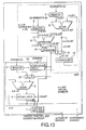
- the periodic function generating circuit 100 includes an integer integrating section 110, a fraction integrating section 120 and a function table ROM 1.
- the function table ROM 1 stores a function table represents relationship between dependent variables and independent variables of a periodic function.
- each of dependent variables of a periodic function are generated as a multiple of a unit U , namely, N times U , where U is a rational number and N is a natural number.
- the unit U is transformed into a sum of a natural number A and a fractional expression C / B , where values B and C are natural numbers.
- the integer integrating section 110 In order to generate a multiple of the unit U , the integer integrating section 110 generates a series of multiples A , 2A , ⁇ , NA , ⁇ and the fraction integrating section 120 synchronously generates a series of multiples C, 2C , ⁇ , NC , ⁇ .
- the fraction integrating section 120 directs the integer integrating section 110 to modify the corresponding multiple of A.
- the integer integrating section 110 outputs modified multiple of A as a multiple of the unit U .
- the integer integrating section 110 outputs the multiple A as a multiple of the unit U without modification.
- the function table ROM 1 In response to the multiple of the unit U , the function table ROM 1 outputs a independent variable corresponding to the multiple of the unit U .
- the periodic function generating circuit 100 the periodic function generating circuit 100.
- the integer integrating section 110 includes a register 2, an adder 3 and an accumulator 4.
- the adder 3 usually generates a sum of a value stored in the register 2 and a value stored in the accumulator 4, and updates the value stored in the accumulator 4 to the sum at every clock timing.
- the value stored in the accumulator 4 is provided to the function table ROM 1 in order to output the value corresponding to the value stored in the accumulator 4.
- the fraction integrating section 120 generates a multiple of the fraction of the unit U .
- the fraction is a number that can be represented in a fractional expression.
- the fraction integrating section 120 outputs a modification signal to the integer integrating section 110.
- the modification signal directs the integer integrating section 110 to modify the dependent variable. For example, when the multiple of the fraction is less than one, the adder 3 adds a value stored in the register 2 and a value stored in the accumulator 4. On the other hand, when the multiple of the fraction is equal to or larger than one, the adder 3 adds a value stored in the register 2, a value stored in the accumulator 4 and +1.
- the integer integrating section 110 outputs a modified multiple of the unit U when the multiple of the fraction is equal to or larger than one, or outputs the multiple of the unit U when the multiple of the fraction is less than one. Consequently, errors of the dependent variables output by the periodic function generating circuit 100 can be restricted within the minimum bit available for the register 2.
- the fraction integrating section 120 which characterizes this embodiment, generates the modification signal to the integer integrating section 110 when phase difference between theoretical and generated waveforms grows equal to or larger than the minimum bit. Consequently, according to the periodic function generating circuit 100, stack of the phase difference is avoidable.
- the unit U is expressed as a sum of an integer A and a fraction C / B that is less than one, where U is a rational number, A, B and C are natural numbers.
- clock timings when rectangular pulses rise are called as 0th clock, 1st clock, 2nd clock, ⁇ , 19th clock.
- the adder 8 adds the numerator C stored in the register 7 and the value stored in the accumulator 10 (STEP S2).
- the subtractor 6 subtracts the value stored in the register 5 from the output of the adder 8 (STEP S3).
- the accumulator 10 stacks up the numerator C .
- the loop operation is performed from the 1st to 6th clocks in Fig. 7. In these clocks, the accumulator 10 is stacking up the numerator Cand stores 0, 5, 10, ⁇ , 30 one after another ,as errors for generating a multiple of unit U .
- the output of the adder 8 exceeds the denominator B stored in the register 5 and the output of the substractor 6 turns to positive. This means that the multiple of the fraction is larger than one.
- the selector 9 selects the subtractor 6, instead of the adder 8, in order to store the output of the subtractor 6 to the accumulator 10 (STEPS S4, S6).
- the inverter 11 provides the modification signal to the integer integrating section 110 (STEP S7).
- the integer A is set to the register 2 and the accumulator 4 is reset (STEP T1).
- the integer A is 7 and the register 2 stores 7.
- the integer integrating section 110 performs the following operation every clock.
- the adder 3 when the modification signal is sent from the fraction integrating section 120 (STEP T2), the adder 3 generates a sum of the value stored in the register 2, the value stored in the accumulator 4, and a modifier (STEP T5).
- the modifier is predetermined as a natural number that is added at STEP T5 in order to adjust the sum generated by the adder 3.
- the modifier is 1.
- the modification mentioned above corrects error of the multiple of the unit U .
- dependent variables output from the integer integrating section 110 to the function table ROM 1 is modified when the amount of the error exceeds one bit.
- k is a natural number, and for example, is 7th clock in Fig. 7
- the fraction integrating section 120 does not output the modification signal, and the integer integrating section 110 repeatedly generates a sum of the sum generated at previous clock and the value A .
- the fraction integrating section 120 outputs the modification signal to the integer integrating section 110, and in response to the modification signal, the integer integrating section 110 generates a sum of the sum generated at previous clock and the integer A + 1. Therefore, dependent variables referred by the function table ROM 1 is modified when the amount of the error exceeds one bit. Consequently, the periodic function generating circuit 100 can avoid stack of phase difference as shown in Fig. 3 and discontinuity of phase as shown in Fig. 4.
- the rational number is expressed as a sum of an integer and a fraction which is less than one, next, a multiple of the integer and a multiple of the numerator of the fraction are generated, then the multiple of the integer is modified according to the multiple of the fraction and output as the multiple of the rational number.
- the periodic function generating circuit 100 can generate the multiple of the rational number, namely a dependent variable, with error less than one.
- the integer is modified when the multiple of the fraction becomes larger than natural numbers. Therefore, the periodic function generating circuit 100 can avoid discontinuity of phase. Consequently, the periodic function generating circuit 100 can generate a periodic function with high accuracy for a long time.
- the inverter 11 generates the modification signal when the multiple of the fraction becomes larger than a natural number.
- a flag generator 21 generates the modification signal when the multiple of the fraction becomes larger than a multiple of a natural number.
- the flag generator 21 generates the modification signal when the multiple of the fraction becomes larger than 2, 4, 6, ⁇ if the natural number is two.
- a multiple of another natural number instead of the multiple of two, may be available for comparing with the multiple of the fraction.
- the adder 3 when the modification signal occurs, the adder 3 adds the modifier to a sum of the integer A and the value stored in the accumulator 4 at previous clock.
- a modification circuit 20 modifies the integer A in accordance with the output of the flag generator 21. Then the adder 3 adds the modified integer A to the value stored in the accumulator 4 at previous clock.
- the modification circuit 20 executes addition or subtraction between the integer A stored in the register 2 and a modifier set from outside of the modification circuit 20. The modifier is referred when the modification signal occurs.
- the amount of the modifier is decided according to the natural number whose multiple compared with the multiple of the fraction in order to generate the modification signal by the flag generator 21.
- the modification signal is input to the adder 3.
- the flag generator 21 generates modification signals and inputs the modification signal to the modification circuit 20 and a selector 22.
- the selector 22 selects one of the outputs from the register 2 and from the modification circuit 20 in accordance with the modification signal.
- the periodic function generating circuit 200 modifies the multiple of the integer A when a multiple of the numerator C becomes larger than a multiple of two.
- the inverter 11 generates a modification signal at 7th and 14th clocks.
- the flag generator 21 generates a modification signal only at 14th clock.
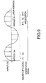
- the periodic function generating circuit 200 generates a periodic function as shown in Fig. 12. This shows that the second embodiment is useful when frequency of modification should be low.
- the modification circuit 20 generates the modified integer A at every clock when the modification signal occurs. If the frequency of the modification signal is predetermined, the amount of the modified integer A can thereby be predetermined and be fixed.
- the periodic function generating circuit 300 includes a register 30, instead of the modification circuit 20.
- the register 30 stores the modified integer A.
- the adder 3 receives the alternative of the integer A stored in the register 2 and the modified integer A stored in the register 30. The alternative is selected by a selector 22 according to the inverter 11.
- the periodic function generating circuit 300 includes the fraction integrating section 120, which is the same one included in the periodic function generating circuit 100. Therefore, one modification signal occurs when a multiple of the fraction is larger than a natural number.
- the modified integer A is always larger than the integer A.
- the modified integer A is either smaller or larger than the integer A .
- the selector 22 would output the modified integer A when a multiple of the numerator C becomes larger than a multiple of two.
- the modified integer A stored in the register 30 should be decided in consideration to the frequency of the modification signal.
Landscapes
- Engineering & Computer Science (AREA)
- Theoretical Computer Science (AREA)
- Physics & Mathematics (AREA)
- General Physics & Mathematics (AREA)
- General Engineering & Computer Science (AREA)
- Computing Systems (AREA)
- Mathematical Optimization (AREA)
- Mathematical Physics (AREA)
- Pure & Applied Mathematics (AREA)
- Mathematical Analysis (AREA)
- Computational Mathematics (AREA)
- Stabilization Of Oscillater, Synchronisation, Frequency Synthesizers (AREA)
- Complex Calculations (AREA)
Abstract
Description
Claims (18)
- A method of generating a multiple of a unit U, N times U, by a digital circuit, where U is a rational number and N is a natural number, comprising the steps of:storing values A, B and C, where A, B and C are natural numbers, A > 1, B> C and U = A + C/B;generating a multiple of A, N times A, and a multiple of C, N times C;comparing the value B with the multiple of C;modifying the multiple of A according to the result of the comparing step; andoutputting the modified multiple of A as the multiple of U.
- The method claimed in claim 1, wherein when the result of the comparing step is that the multiple of C is equal to or larger than the value B, the modifying step comprising the steps of:modifying the multiple of A; andsubtracting the value B from the multiple of C.
- The method claimed in claim 1, wherein when the result of the comparing step is that the multiple of C is equal to or larger than a value MB, where M is a predetermined natural number, the modifying step comprising the steps of:modifying the multiple of A; andsubtracting the value MB from the multiple of C.
- The method claimed in claim 1, wherein the C/B represents a repeating decimal.
- A method of generating a dependent variable of a periodic function whose independent variable is a multiple of a unit U, N times U, by a digital circuit, where U is a rational number and N is a natural number, comprising the steps of:storing values A, B and C, where A, B and C are natural numbers, A > 1, B > C and U = A + C/B;generating a multiple of A, N times A, and a multiple of C, N times C;comparing the value B with the multiple of C;modifying the multiple of A according to the result of the comparing step; andextracting a value corresponding to the modified multiple of A from a function table, which represents relationship between the dependent and independent variables of the periodic function and is previously stored in a memory device, as the dependent variable corresponding to the multiple of U.
- The method claimed in claim 5, wherein when the result of the comparing step is that the multiple of C is equal to or larger than the value B, the modifying step comprising the steps of:modifying the multiple of A; andsubtracting the value B from the multiple of C.
- The method claimed in claim 5, wherein when the result of the comparing step is that the multiple of C is equal to or larger than a value MB, where M is a predetermined natural number, the modifying step comprising the steps of:modifying the multiple of A; andsubtracting the value MB from the multiple of C.
- The method claimed in claim 5, wherein the C/B represents a repeating decimal.
- A digital circuit for generating a multiple of a unit U, N times U, where U is a rational number and N is a natural number, comprising:wherein the first calculating circuit outputs the modified multiple of A as the multiple of U.first, second and third registers for storing values A, B and C, respectively, where A, B and C are natural numbers, A > 1, B > C and U = A + C/B;first and second calculating circuits for generating a multiple of A, N times A, and a multiple of C, N times C, respectively;a subtractor for generating a difference between the multiple of C and the value B; anda modifying circuit for modifying the multiple of A according to the output of the subtractor,
- The digital circuit claimed in claim 9, wherein:the first calculating circuit comprises an accumulator and an adder that adds the value stored in the first register to the value stored in the accumulator; andthe modifying circuit directs the adder to add +1 to its output when the output of the subtractor represents that the multiple of C is equal to or larger than the value B.
- The digital circuit claimed in claim 9, wherein:the first calculating circuit comprises an accumulator and an adder;the modifying circuit comprises an adjusting circuit for adjusting the value stored in the first register with reference to a predetermined value, and a selector for selecting one of the outputs of the adder and the adjusting circuit according to the output of the subtractor; andthe adder adds the value stored in the accumulator to the output of the selector.
- The digital circuit claimed in claim 9, wherein:the first calculating circuit comprises an accumulator and an adder;the modifying circuit comprises a fourth register for storing a value which is different from the value A, and a selector for selecting one of the values stored in the first and fourth registers according to the output of the subtractor; andthe adder adds the value stored in the accumulator to the output of the selector.
- The digital circuit claimed in claim 9, wherein the C/B represents a repeating decimal.
- A digital circuit for generating a dependent variable of a periodic function whose independent variable is a multiple of a unit U, N times U, where U is a rational number and N is a natural number, comprising:first, second and third registers for storing values A, B and C respectively, where A, B and C are natural numbers, A > 1, B > C and U = A + C/B;first and second calculating circuits for generating a multiple of A, N times A, and a multiple of C, N times C, respectively;a subtractor for generating a difference between the multiple of C and the value B;a modifying circuit for modifying the multiple of A according to the output of the subtractor; anda memory device for storing a function table which represents relationship between the dependent and independent variables of the periodic function and for outputting a value corresponding to the modified multiple of A on the function table as the dependent variable corresponding to the multiple of U.
- The digital circuit claimed in claim 14, wherein:the first calculating circuit comprises an accumulator and an adder that adds the value stored in the first register to the value stored in the accumulator; andthe modifying circuit directs the adder to add +1 to its output when the output of the subtractor represents that the multiple of C is equal to or larger than the value B.
- The digital circuit claimed in claim 14, wherein:the first calculating circuit comprises an accumulator and an adder;the modifying circuit comprises an adjusting circuit for adjusting the value stored in the first register with reference to a predetermined value, and a selector for selecting one of the outputs of the adder and the adjusting circuit according to the output of the subtractor; andthe adder adds the value stored in the accumulator to the output of the selector.
- The digital circuit claimed in claim 14, wherein:the first calculating circuit comprises an accumulator and an adder;the modifying circuit comprises a fourth register for storing a value which is different from the value A, and a selector for selecting one of the values stored in the first and fourth registers according to the output of the subtractor; andthe adder adds the value stored in the accumulator to the output of the selector.
- The digital circuit claimed in claim 14, wherein the C/B represents a repeating decimal.
Applications Claiming Priority (2)
| Application Number | Priority Date | Filing Date | Title |
|---|---|---|---|
| JP2000380234 | 2000-12-14 | ||
| JP2000380234A JP2002182898A (en) | 2000-12-14 | 2000-12-14 | Method and circuit for generating integrated value and period function |
Publications (2)
| Publication Number | Publication Date |
|---|---|
| EP1215558A2 true EP1215558A2 (en) | 2002-06-19 |
| EP1215558A3 EP1215558A3 (en) | 2005-03-30 |
Family
ID=18848459
Family Applications (1)
| Application Number | Title | Priority Date | Filing Date |
|---|---|---|---|
| EP01129723A Withdrawn EP1215558A3 (en) | 2000-12-14 | 2001-12-13 | Method and circuit for calculating multiple of unit value and generating a periodic function |
Country Status (3)
| Country | Link |
|---|---|
| US (1) | US7069283B2 (en) |
| EP (1) | EP1215558A3 (en) |
| JP (1) | JP2002182898A (en) |
Cited By (3)
| Publication number | Priority date | Publication date | Assignee | Title |
|---|---|---|---|---|
| EP1550934A1 (en) * | 2003-12-29 | 2005-07-06 | Teradyne, Inc. | Multi-stage NCO |
| WO2005073829A1 (en) * | 2004-01-28 | 2005-08-11 | Koninklijke Philips Electronics, N.V. | A free-running numerically-controlled oscillator using complex multiplication with compensation for amplitude variation due to cumulative round-off errors |
| CN1797955B (en) * | 2004-12-29 | 2011-08-24 | 泰拉丁公司 | Multi-Stage Digital Counting Oscillator |
Family Cites Families (13)
| Publication number | Priority date | Publication date | Assignee | Title |
|---|---|---|---|---|
| JPS6027408B2 (en) | 1979-05-14 | 1985-06-28 | ケイディディ株式会社 | Digital signal processing method |
| SE447618B (en) * | 1985-04-12 | 1986-11-24 | Ericsson Telefon Ab L M | SET AND DEVICE FOR PHASING A CONTROLLED OSCILLATOR'S SIGNAL TO A REFERENCE Oscillator SIGNAL |
| JPH0683067B2 (en) * | 1987-10-13 | 1994-10-19 | 松下電器産業株式会社 | Frequency divider |
| US4969118A (en) | 1989-01-13 | 1990-11-06 | International Business Machines Corporation | Floating point unit for calculating A=XY+Z having simultaneous multiply and add |
| US4998072A (en) * | 1990-02-20 | 1991-03-05 | John Fluke Mfg. Co., Inc. | High resolution direct digital synthesizer |
| JPH0743620B2 (en) | 1990-04-12 | 1995-05-15 | 松下電器産業株式会社 | Periodic function generator |
| JPH0437205A (en) * | 1990-05-31 | 1992-02-07 | Sony Corp | Oscillator |
| JPH0730373A (en) | 1993-07-07 | 1995-01-31 | Nippondenso Co Ltd | Digital filter |
| JP3086706B2 (en) * | 1995-08-03 | 2000-09-11 | アンリツ株式会社 | Rational frequency divider and frequency synthesizer using the same |
| US5781459A (en) * | 1996-04-16 | 1998-07-14 | Bienz; Richard Alan | Method and system for rational frequency synthesis using a numerically controlled oscillator |
| US6088800A (en) * | 1998-02-27 | 2000-07-11 | Mosaid Technologies, Incorporated | Encryption processor with shared memory interconnect |
| JP2000196690A (en) | 1998-12-24 | 2000-07-14 | Toshiba Tec Corp | Modulation device and modulation method |
| JP3226884B2 (en) | 1999-01-26 | 2001-11-05 | エヌイーシーマイクロシステム株式会社 | Periodic function generator |
-
2000
- 2000-12-14 JP JP2000380234A patent/JP2002182898A/en active Pending
-
2001
- 2001-12-13 EP EP01129723A patent/EP1215558A3/en not_active Withdrawn
- 2001-12-14 US US10/014,575 patent/US7069283B2/en not_active Expired - Fee Related
Cited By (6)
| Publication number | Priority date | Publication date | Assignee | Title |
|---|---|---|---|---|
| EP1550934A1 (en) * | 2003-12-29 | 2005-07-06 | Teradyne, Inc. | Multi-stage NCO |
| US7064616B2 (en) | 2003-12-29 | 2006-06-20 | Teradyne, Inc. | Multi-stage numeric counter oscillator |
| WO2005073829A1 (en) * | 2004-01-28 | 2005-08-11 | Koninklijke Philips Electronics, N.V. | A free-running numerically-controlled oscillator using complex multiplication with compensation for amplitude variation due to cumulative round-off errors |
| US7707235B2 (en) | 2004-01-28 | 2010-04-27 | Nxp B. V. | Free-running numerically-controlled oscillator using complex multiplication with compensation for amplitude variation due to cumulative round-off errors |
| CN1914579B (en) * | 2004-01-28 | 2010-08-11 | Nxp股份有限公司 | Uses a free-running digitally controlled oscillator with complex multiplication to compensate for amplitude changes due to accumulated round-off errors |
| CN1797955B (en) * | 2004-12-29 | 2011-08-24 | 泰拉丁公司 | Multi-Stage Digital Counting Oscillator |
Also Published As
| Publication number | Publication date |
|---|---|
| US7069283B2 (en) | 2006-06-27 |
| EP1215558A3 (en) | 2005-03-30 |
| US20020078111A1 (en) | 2002-06-20 |
| JP2002182898A (en) | 2002-06-28 |
Similar Documents
| Publication | Publication Date | Title |
|---|---|---|
| US5894428A (en) | Recursive digital filter | |
| US4460890A (en) | Direct digital to digital sampling rate conversion, method and apparatus | |
| US5818888A (en) | Sample rate converter | |
| EP0419622B1 (en) | Frequency synthesisers with fractional division | |
| US5159339A (en) | Sampling rate converter for signals having a non-integer sampling ratio | |
| US6147632A (en) | Sampling frequency conversion apparatus and fractional frequency dividing apparatus for sampling frequency conversion | |
| KR100620934B1 (en) | Asynchronous signal input apparatus and sampling frequency conversion apparatus | |
| US7205800B2 (en) | Clock frequency divider circuit | |
| US7411525B2 (en) | Sampling rate converting method and circuit | |
| US7069283B2 (en) | Method and circuit for calculating multiple of unit value and generating a periodic function | |
| US5253052A (en) | Apparatus for detecting relative motion between contents of successive fields of a video signal | |
| US8380773B2 (en) | System and method for adaptive nonlinear filtering | |
| US7209937B2 (en) | Method and apparatus for generation of arbitrary mono-cycle waveforms | |
| US7072920B2 (en) | Method and apparatus for digital frequency conversion | |
| JPH1079650A (en) | Clock generation circuit | |
| JP3223280B2 (en) | Waveform data interpolation device | |
| JP3223555B2 (en) | Waveform reading device | |
| EP1098507A2 (en) | Image processing apparatus | |
| KR20050084345A (en) | Digital sampling frequency converter | |
| KR0149323B1 (en) | Digital Audio Volume Control | |
| JP2792489B2 (en) | Adaptive filter | |
| JPH0677769A (en) | Fir digital filter | |
| JP3566613B2 (en) | Tone generator and digital tone generation method | |
| JPH09312549A (en) | Rate conversion circuit | |
| JPH0883167A (en) | Random number generator |
Legal Events
| Date | Code | Title | Description |
|---|---|---|---|
| PUAI | Public reference made under article 153(3) epc to a published international application that has entered the european phase |
Free format text: ORIGINAL CODE: 0009012 |
|
| AK | Designated contracting states |
Kind code of ref document: A2 Designated state(s): AT BE CH CY DE DK ES FI FR GB GR IE IT LI LU MC NL PT SE TR |
|
| AX | Request for extension of the european patent |
Free format text: AL;LT;LV;MK;RO;SI |
|
| RAP1 | Party data changed (applicant data changed or rights of an application transferred) |
Owner name: NEC ELECTRONICS CORPORATION |
|
| PUAL | Search report despatched |
Free format text: ORIGINAL CODE: 0009013 |
|
| AK | Designated contracting states |
Kind code of ref document: A3 Designated state(s): AT BE CH CY DE DK ES FI FR GB GR IE IT LI LU MC NL PT SE TR |
|
| AX | Request for extension of the european patent |
Extension state: AL LT LV MK RO SI |
|
| 17P | Request for examination filed |
Effective date: 20050216 |
|
| STAA | Information on the status of an ep patent application or granted ep patent |
Free format text: STATUS: THE APPLICATION HAS BEEN WITHDRAWN |
|
| AKX | Designation fees paid |
Designated state(s): NL |
|
| 18W | Application withdrawn |
Effective date: 20051122 |
|
| REG | Reference to a national code |
Ref country code: DE Ref legal event code: 8566 |