EP1215554A1 - Dynamic optimizing method for speed data and positioning device using this method - Google Patents
Dynamic optimizing method for speed data and positioning device using this method Download PDFInfo
- Publication number
- EP1215554A1 EP1215554A1 EP00956919A EP00956919A EP1215554A1 EP 1215554 A1 EP1215554 A1 EP 1215554A1 EP 00956919 A EP00956919 A EP 00956919A EP 00956919 A EP00956919 A EP 00956919A EP 1215554 A1 EP1215554 A1 EP 1215554A1
- Authority
- EP
- European Patent Office
- Prior art keywords
- speed
- speed data
- instruction
- pattern
- maximum value
- Prior art date
- Legal status (The legal status is an assumption and is not a legal conclusion. Google has not performed a legal analysis and makes no representation as to the accuracy of the status listed.)
- Withdrawn
Links
Images

Classifications
-
- G—PHYSICS
- G05—CONTROLLING; REGULATING
- G05B—CONTROL OR REGULATING SYSTEMS IN GENERAL; FUNCTIONAL ELEMENTS OF SUCH SYSTEMS; MONITORING OR TESTING ARRANGEMENTS FOR SUCH SYSTEMS OR ELEMENTS
- G05B19/00—Program-control systems
- G05B19/02—Program-control systems electric
- G05B19/18—Numerical control [NC], i.e. automatically operating machines, in particular machine tools, e.g. in a manufacturing environment, so as to execute positioning, movement or co-ordinated operations by means of program data in numerical form
- G05B19/416—Numerical control [NC], i.e. automatically operating machines, in particular machine tools, e.g. in a manufacturing environment, so as to execute positioning, movement or co-ordinated operations by means of program data in numerical form characterised by control of velocity, acceleration or deceleration
-
- G—PHYSICS
- G05—CONTROLLING; REGULATING
- G05B—CONTROL OR REGULATING SYSTEMS IN GENERAL; FUNCTIONAL ELEMENTS OF SUCH SYSTEMS; MONITORING OR TESTING ARRANGEMENTS FOR SUCH SYSTEMS OR ELEMENTS
- G05B2219/00—Program-control systems
- G05B2219/30—Nc systems
- G05B2219/34—Director, elements to supervisory
- G05B2219/34182—Variable resolution
-
- G—PHYSICS
- G05—CONTROLLING; REGULATING
- G05B—CONTROL OR REGULATING SYSTEMS IN GENERAL; FUNCTIONAL ELEMENTS OF SUCH SYSTEMS; MONITORING OR TESTING ARRANGEMENTS FOR SUCH SYSTEMS OR ELEMENTS
- G05B2219/00—Program-control systems
- G05B2219/30—Nc systems
- G05B2219/43—Speed, acceleration, deceleration control ADC
- G05B2219/43001—Speed, feed, infeed, acceleration, stopping problems
-
- G—PHYSICS
- G05—CONTROLLING; REGULATING
- G05B—CONTROL OR REGULATING SYSTEMS IN GENERAL; FUNCTIONAL ELEMENTS OF SUCH SYSTEMS; MONITORING OR TESTING ARRANGEMENTS FOR SUCH SYSTEMS OR ELEMENTS
- G05B2219/00—Program-control systems
- G05B2219/30—Nc systems
- G05B2219/43—Speed, acceleration, deceleration control ADC
- G05B2219/43012—Profile is defined by series of bits, for each actuator, sensor
-
- G—PHYSICS
- G05—CONTROLLING; REGULATING
- G05B—CONTROL OR REGULATING SYSTEMS IN GENERAL; FUNCTIONAL ELEMENTS OF SUCH SYSTEMS; MONITORING OR TESTING ARRANGEMENTS FOR SUCH SYSTEMS OR ELEMENTS
- G05B2219/00—Program-control systems
- G05B2219/30—Nc systems
- G05B2219/43—Speed, acceleration, deceleration control ADC
- G05B2219/43093—Speed pattern, table together with timing data in ram
Definitions
- the present invention relates to a method for preparing a speed instruction pattern for a servo motor in a positioning device.
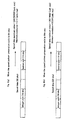
- the speed pattern preparation cycle and speed data are set as shown in Figs. 3, that is, speed data is set to 32 bits in both Fig. 3(a) and Fig. 3(b), and by means of the fixed decimal mode, 16 bits are set for the integer part and 16 bits are set for the decimal part to fix the decimal point position.
- the speed pattern preparation cycle as a cycle for outputting speed data is set to 8m sec in the case of Fig. 3(a) and 64m sec in the case of Fig. 3(b).
- the speed data maximum value is 245752500 (unit: min) and the minimum resolution is 0.11 (unit: min), on the other hand, in Fig. 3(b), the speed lowers and the resolution increases to a degree at which the speed data maximum value is 30719062 (unit: min) and the minimum resolution is 0.014 (unit: min).
- the speed minimum resolution to be used inside the a positioning device has conventionally been set to a fixed value of 0.11 (unit: min) in Fig. 3(a) and 0.014 (unit: min) in Fig. 3(b) based on a speed pattern preparation cycle, speed unit specified by a user, and speed data maximum value specified by the user.
- an object of the invention is to provide a dynamic optimizing method for speed data, which does not fix the resolution of speed data to be used inside a positioning device, but distinguishes a dynamic optimum resolution, and in accordance with various speed pattern preparation cycles, user specified speed units, and speed data maximum values and minimum resolutions, can provide an environment which guarantees constant accuracy in a speed pattern determined by the user.
- Another object of the invention is to provide a positioning device using this method.
- the present invention provides a dynamic optimizing method for speed data used for preparing a speed instruction pattern fed to a servo motor in a positioning device, characterized in that a speed pattern generator is provided, which calculates a desired speed pattern when a moving distance, speed, acceleration time, and deceleration time are inputted, a speed pattern preparation cycle can be specified by a user without a possibility that the speed data maximum value and minimum resolution of the speed data are modified.
- the dynamic optimizing method for speed data is characterized in that a combination of a speed data maximum value and a minimum resolution can be selected by a user.
- the speed data maximum value and minimum resolution are prevented from changing by shifting the decimal part of the speed data to the right or left.
- a positioning device using a servo motor comprises a moving instruction input unit, a speed pattern preparation unit for inputting a moving instruction from this moving instruction input unit, a speed instruction unit for outputting a speed instruction based on a speed instruction pattern from the speed pattern preparation unit in accordance with the speed instruction cycle specified by a user, and a servo control unit for driving the servo motor based on the speed instruction from this speed instruction unit.
- the speed pattern preparation unit 1 is a controller comprising a CPU module and a motion module for a positioning device.
- the moving instruction 2 is to be inputted into the speed pattern preparation unit 1, and includes a speed, moving distance, and acceleration and deceleration constant (S-shaped pattern).
- the speed pattern preparation cycle 3 indicates a cycle (scanning cycle 8ms through 64ms) of a speed instruction outputted by the positioning device, and is specified by a user.
- the computation result 4 (speed instruction unit) is based on the speed pattern preparation unit 1, and outputs a speed instruction in each cycle based on the prepared speed pattern.
- the servo control unit 5 drives the servo motor 6 based on the speed instruction, and controls the motor position and speed.
- the speed pattern preparation unit 1 calculates a speed pattern based on the inputted speed pattern preparation cycle 3 and moving instruction (moving distance and acceleration and deceleration time) 2, and the size of the computing range in this case is set to have a fixed length inside the positioning device.
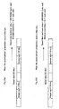
- this computing range with a fixed length as shown in Figs. 2, when speed data is held in the fixed decimal mode, the size of speed data is fixed to a size of 16 bits, 32 bits, or 64 bits.
- Figs. 2 show an example in which the speed data size is 32 bits.
- the fixed decimal mode is characterized in that the sum of significant digits of the integer part and significant digits of the decimal part from the fixed decimal point position are always fixed, so that under the same speed pattern preparation cycle condition, if the integer part is taken to be large, the decimal part becomes small, and the resolution lowers. On the contrary, if the decimal part is taken to be large, the integer part becomes small, and the integer output range is reduced.
- the integer part and decimal part can be fixed at an optimum ratio, for example, an integer part is fixed to be 16 bits and the decimal part is fixed to be 16 bits.
- the speed pattern preparation cycle is dynamically changed, if the ratio of the integer part and the decimal part is fixed, the speed pattern preparation cycle influences the speed pattern resolution and speed data maximum value, so that it is necessary to modify the user program for each change in the speed pattern preparation cycle. That is, in the example of Figs. 3, when the speed pattern preparation cycle changes from 8ms to 64ms as shown in Fig. 3(b), it is necessary to modify the program based on.the corresponding ratio of the speed data maximum value and minimum resolution of Fig. 3(a).
- the invention is constructed so that, as shown in Fig. 2(b), even when the speed pattern preparation cycle 3 is changed to 64ms, the decimal part is shifted to the right to prevent the integer part of 19 bits, decimal part of 13 bits, speed data maximum value, and minimum resolution from changing, wherein by shifting the decimal part to the right or left, even when the speed pattern preparation cycle is changed, the speed data maximum value and minimum resolution do not change, and this makes modification of the user program unnecessary.
- this combination of the speed data maximum value and minimum resolution is arranged so as to be set when inputting the moving instruction 2 and selected by a user, the positioning device shifts the decimal part of the speed data in accordance with the speed pattern preparation cycle so as to prevent the specified inputted speed data maximum value and minimum resolution from changing, so that a user can select an optimum data holding method, and can efficiently utilize controller resources in program preparation, look-ahead, and analysis.
- a dynamic optimizing method for speed data used for preparing a speed instruction pattern fed to a servo motor in a positioning device is characterized in that a speed pattern generator for calculating a desired speed pattern when a moving distance, speed, acceleration time, and deceleration time are inputted, the speed pattern preparation cycle can be specified by a user without a possibility of modifying the speed data maximum value and minimum resolution of the speed data.
- the speed pattern preparation cycle is changed, compensation is carried out so as to prevent the speed data maximum value and minimum resolution of the speed data from changing, the combination of the speed data maximum value and minimum resolution can be selected by a user, and furthermore, when a user specifies the speed pattern preparation cycle, by shifting the decimal part of the speed data to the right or left, the speed data maximum value and minimum resolution can be prevented from changing. Accordingly, it is unnecessary for a user to modify the user program even when the user changes the speed pattern preparation cycle.
- the invention provides a positioning control device which a user can easily operate. Furthermore, this device is extremely effective for control of a linear motor which requires a high feeding speed and highly accurate positioning.
Landscapes
- Engineering & Computer Science (AREA)
- Human Computer Interaction (AREA)
- Manufacturing & Machinery (AREA)
- Physics & Mathematics (AREA)
- General Physics & Mathematics (AREA)
- Automation & Control Theory (AREA)
- Control Of Position Or Direction (AREA)
- Control Of Electric Motors In General (AREA)
- Numerical Control (AREA)
- Control Of Velocity Or Acceleration (AREA)
Abstract
Description
Claims (4)
- A dynamic optimizing method for speed data used for preparing a speed instruction pattern fed to a servo motor in a positioning device, wherein
a speed pattern generator for calculating a desired speed pattern when a moving distance, speed, acceleration time and deceleration time are inputted is provided, and the speed pattern preparation cycle is allowed to be specified by a user without a possibility that the speed data maximum value and minimum resolution of the speed data are changed. - The dynamic optimizing method for speed data according to Claim 1, wherein a combination of the speed data maximum value and minimum resolution is allowed to be selected by a user.
- The dynamic optimizing method for speed data according to Claim 1, wherein when a user specifies the speed pattern preparation cycle, the decimal part of the speed data is shifted to the right or left so as to prevent the speed data maximum value and minimum resolution from being changed.
- A positioning device using a servo motor, comprising: a moving instruction input unit, a speed pattern preparation unit for inputting a moving instruction from the moving instruction input unit, a speed instruction unit for outputting a speed instruction based on the speed instruction pattern from the speed pattern preparation unit in accordance with the speed instruction cycle specified by a user, and a servo control unit for driving the servo motor based on the speed instruction from the speed instruction unit.
Applications Claiming Priority (3)
| Application Number | Priority Date | Filing Date | Title |
|---|---|---|---|
| JP26754799A JP2001092533A (en) | 1999-09-21 | 1999-09-21 | Dynamic optimization method of speed data |
| JP26754799 | 1999-09-21 | ||
| PCT/JP2000/006004 WO2001022184A1 (en) | 1999-09-21 | 2000-09-04 | Dynamic optimizing method for speed data and positioning device using this method |
Publications (2)
| Publication Number | Publication Date |
|---|---|
| EP1215554A1 true EP1215554A1 (en) | 2002-06-19 |
| EP1215554A4 EP1215554A4 (en) | 2002-11-06 |
Family
ID=17446340
Family Applications (1)
| Application Number | Title | Priority Date | Filing Date |
|---|---|---|---|
| EP00956919A Withdrawn EP1215554A4 (en) | 1999-09-21 | 2000-09-04 | DYNAMIC OPTIMIZATION METHOD FOR SPEED DATA AND POSITIONING DEVICE OPERATING ACCORDING TO THIS METHOD |
Country Status (5)
| Country | Link |
|---|---|
| US (1) | US6765360B1 (en) |
| EP (1) | EP1215554A4 (en) |
| JP (1) | JP2001092533A (en) |
| TW (1) | TW439021B (en) |
| WO (1) | WO2001022184A1 (en) |
Cited By (1)
| Publication number | Priority date | Publication date | Assignee | Title |
|---|---|---|---|---|
| CN103064425A (en) * | 2012-12-31 | 2013-04-24 | 中联重科股份有限公司 | Method, system and engineering machinery for improving boom movement stability |
Families Citing this family (3)
| Publication number | Priority date | Publication date | Assignee | Title |
|---|---|---|---|---|
| CN102236338B (en) * | 2010-04-22 | 2013-11-13 | 上海微电子装备有限公司 | Realization method of four-step constant value generator |
| JP6363643B2 (en) * | 2016-03-04 | 2018-07-25 | ファナック株式会社 | Numerical control device that can increase the number of analysis digits of program command |
| CN105867313B (en) * | 2016-05-25 | 2017-03-29 | 湖北工业大学 | A kind of digital stamping feeding intelligence real-time speed Forecasting Methodology |
Family Cites Families (12)
| Publication number | Priority date | Publication date | Assignee | Title |
|---|---|---|---|---|
| US3941988A (en) * | 1973-09-04 | 1976-03-02 | Danly Machine Corporation | Method and apparatus for numerical control |
| US4469993A (en) * | 1981-03-03 | 1984-09-04 | Swanson Systems, Inc. | Programmable multiple position machine |
| US4751441A (en) * | 1985-05-31 | 1988-06-14 | Cambrian Consultants, Inc. | Transducer position control system for disk storage equipment |
| GB2188720B (en) * | 1986-04-04 | 1990-12-19 | Data Recording Instr Co | Improved position control system |
| US4782449A (en) * | 1986-04-17 | 1988-11-01 | Glasstech, Inc. | Position controller for glass sheet processing system |
| JPH02126307A (en) * | 1988-11-04 | 1990-05-15 | Sanyo Electric Co Ltd | Motor speed control system |
| JPH02178811A (en) * | 1988-12-29 | 1990-07-11 | Hitachi Seiko Ltd | Servo controller |
| JP2906526B2 (en) * | 1990-02-06 | 1999-06-21 | 株式会社安川電機 | Motor control device |
| JPH05250039A (en) * | 1992-03-04 | 1993-09-28 | Fujitsu Ltd | Digital servo controller |
| JP3526910B2 (en) * | 1994-05-13 | 2004-05-17 | 東芝機械株式会社 | Preprocessing method of numerical control command data of numerical controller |
| US6571138B1 (en) * | 1998-02-23 | 2003-05-27 | Mitsubishi Denki Kabushiki Kaisha | Location programming apparatus and location programming method |
| JP2000047719A (en) * | 1998-07-31 | 2000-02-18 | Toshiba Mach Co Ltd | Numerical controller |
-
1999
- 1999-09-21 JP JP26754799A patent/JP2001092533A/en active Pending
-
2000
- 2000-09-04 EP EP00956919A patent/EP1215554A4/en not_active Withdrawn
- 2000-09-04 WO PCT/JP2000/006004 patent/WO2001022184A1/en not_active Ceased
- 2000-09-04 US US10/088,094 patent/US6765360B1/en not_active Expired - Fee Related
- 2000-09-15 TW TW089118997A patent/TW439021B/en not_active IP Right Cessation
Cited By (2)
| Publication number | Priority date | Publication date | Assignee | Title |
|---|---|---|---|---|
| CN103064425A (en) * | 2012-12-31 | 2013-04-24 | 中联重科股份有限公司 | Method, system and engineering machinery for improving boom movement stability |
| CN103064425B (en) * | 2012-12-31 | 2016-02-24 | 中联重科股份有限公司 | Method, system and engineering machinery for improving boom movement stability |
Also Published As
| Publication number | Publication date |
|---|---|
| WO2001022184A1 (en) | 2001-03-29 |
| EP1215554A4 (en) | 2002-11-06 |
| TW439021B (en) | 2001-06-07 |
| JP2001092533A (en) | 2001-04-06 |
| US6765360B1 (en) | 2004-07-20 |
Similar Documents
| Publication | Publication Date | Title |
|---|---|---|
| EP0394474A1 (en) | Spline interpolation system | |
| EP0417312A1 (en) | Feedforward control unit for servomotor | |
| US7548795B2 (en) | Numerical control system | |
| WO1992015068A1 (en) | Computer control system for generating geometric designs | |
| CN107153404B (en) | The numerical control device of the parsing digit of program instruction can be increased | |
| US5270627A (en) | Machine tool control system | |
| US5708586A (en) | Computerized numerical control apparatus for correcting dynamic error and method therefor | |
| US6765360B1 (en) | Dynamic optimizing method for speed data and positioning device using this method | |
| KR20020067893A (en) | A Robot | |
| EP0107794A1 (en) | Numerical control system | |
| KR100338469B1 (en) | Numerical control apparatus and feed control processing method therefor | |
| JP2001154719A (en) | Free curve interpolation method | |
| KR100405718B1 (en) | A method for controlling position of a material and a system thereof | |
| Tlusty et al. | Numerical and adaptive control for die sinking | |
| JP2613784B2 (en) | Interpolator | |
| JPH08263129A (en) | Pulse generating circuit | |
| JP3548272B2 (en) | Drive pattern generator | |
| AU645251B2 (en) | Real-time adjustable-transform device driver | |
| KR20240159303A (en) | Apparatus and method for controlling motor driven power steering system | |
| WO2026042363A1 (en) | Control system, control method, and program | |
| JPH07191707A (en) | Controller | |
| JPH0769731B2 (en) | Position control method | |
| SU729552A1 (en) | Method of control of industrial robot movement | |
| JP3700810B2 (en) | Data conversion method and apparatus | |
| Kim et al. | Robot Position Control Based on a Transputer Network with a Contactless Sensor |
Legal Events
| Date | Code | Title | Description |
|---|---|---|---|
| PUAI | Public reference made under article 153(3) epc to a published international application that has entered the european phase |
Free format text: ORIGINAL CODE: 0009012 |
|
| 17P | Request for examination filed |
Effective date: 20020320 |
|
| AK | Designated contracting states |
Kind code of ref document: A1 Designated state(s): AT BE CH CY DE DK ES FI FR GB GR IE IT LI LU MC NL PT SE |
|
| AX | Request for extension of the european patent |
Free format text: AL;LT;LV;MK;RO;SI |
|
| RIC1 | Information provided on ipc code assigned before grant |
Free format text: 7G 05D 3/12 A, 7G 05B 19/416 B |
|
| A4 | Supplementary search report drawn up and despatched |
Effective date: 20020920 |
|
| AK | Designated contracting states |
Kind code of ref document: A4 Designated state(s): AT BE CH CY DE DK ES FI FR GB GR IE IT LI LU MC NL PT SE |
|
| 17Q | First examination report despatched |
Effective date: 20030206 |
|
| STAA | Information on the status of an ep patent application or granted ep patent |
Free format text: STATUS: THE APPLICATION IS DEEMED TO BE WITHDRAWN |
|
| 18D | Application deemed to be withdrawn |
Effective date: 20030819 |
|
| RBV | Designated contracting states (corrected) |
Designated state(s): DE FI FR GB IT |