EP1215464B1 - Self-actuating firearm - Google Patents
Self-actuating firearm Download PDFInfo
- Publication number
- EP1215464B1 EP1215464B1 EP01128118A EP01128118A EP1215464B1 EP 1215464 B1 EP1215464 B1 EP 1215464B1 EP 01128118 A EP01128118 A EP 01128118A EP 01128118 A EP01128118 A EP 01128118A EP 1215464 B1 EP1215464 B1 EP 1215464B1
- Authority
- EP
- European Patent Office
- Prior art keywords
- cylinder
- self
- piston
- chamber
- post
- Prior art date
- Legal status (The legal status is an assumption and is not a legal conclusion. Google has not performed a legal analysis and makes no representation as to the accuracy of the status listed.)
- Expired - Lifetime
Links
Images


Classifications
-
- F—MECHANICAL ENGINEERING; LIGHTING; HEATING; WEAPONS; BLASTING
- F41—WEAPONS
- F41A—FUNCTIONAL FEATURES OR DETAILS COMMON TO BOTH SMALLARMS AND ORDNANCE, e.g. CANNONS; MOUNTINGS FOR SMALLARMS OR ORDNANCE
- F41A5/00—Mechanisms or systems operated by propellant charge energy for automatically opening the lock
- F41A5/18—Mechanisms or systems operated by propellant charge energy for automatically opening the lock gas-operated
Definitions
- the present invention relates to a self-actuating firearm, particularly a gas-operated automatic or semiautomatic firearm.
- a portion of the gas produced by firing moves a piston, by passing from the bore or mouth into an expansion chamber and the piston acts on the loading and firing mechanism.
- the breechblock body moves away from the head and performs its backward stroke, compressing the recoil spring, the case is extracted and expelled and the firing pin is cocked.
- US-3,657,960 (which forms the basis of claim 1) discloses a self aligning gas system wherein a piston sleeve includes a push rod loosely mounted on the sleeve for contacting the bolt assembly.
- the push rod contacts the bolt assembly but is not connected thereto so that when the piston is moved through its work stroke, the push rod drives against the bolt assembly to propel the latter toward its retired position.
- US-3,779,131 discloses a device, for automatically feeding spare cartridges into the firing chamber of a shotgun, which should prevent the deposition of solids and contaminants contained in the gas.
- US-2,149,512 discloses a gas operated rifle while EP-0789217, discloses a gas operated shotgun characterized by a gas port located proximate to the cartridge chamber.
- the aim of the present invention is to provide a self-actuating firearm of the gas-operated type, which is improved with respect to the firearms of the prior art.
- An object of the invention is to provide a gas-operated self-actuating firearm which is constructively simple and particularly reliable.
- An important object of the invention is to provide a gas-operated self-actuating firearm which can be easily disassembled in order to perform ordinary maintenance of the firearm.
- Another object of the invention is to provide a gas-operated self-actuating firearm wherein the gas collection device is not easily clogged by the residues that are present in the gas.
- Figures 1-6 illustrate a rifle, generally designated by the reference numeral 1, comprising a barrel 3 having a bore 5 connected to a firing chamber that accommodates a cartridge 7 and that can be closed by a breechblock 9, in a per se known manner.
- the rifle illustrated in figures 1-6 does not form part of the scope of protection of claim 1.
- the breechblock is actuated by a kinematic system which receives energy from the firing gases that arrive from a gas tap 15, provided in the barrel 3 and connecting the bore 5 of the barrel to an internal chamber 11 of a cylinder 13 which is associated with the barrel 3 and is in turn provided with a passage 17, for the gas.
- the cylinder 13 comprises a piston 19 that can slide on a post 21 which is coaxial to the chamber 11 and has a cylindrical block 23, at the opposite end with respect to the piston 19.
- the cylindrical block 23 protrudes at least partially from a front end 25 of the cylinder 13.
- the post 21 is crossed by an axial passage 27 which is open onto the front part of the block 23 and ends with a radial passage 53 at a wider base 55 of the post 21.
- the piston 19 has a first inside diameter 57, so that it can slide hermetically with respect to the wider base 55 of the post 21, and has a second inside diameter 59, which is greater than the first diameter, so that in a stroke limit position, shown in FIG. 6, the radial passage 53 is open onto the internal chamber 11 of the cylinder 13.
- a flat member 29 is rigidly associated with the piston 19, externally to the cylinder 13, and comprises two protrusions 31 adapted to act on respective pins 33 that are kinematically connected to the kinematic actuation system of the breechblock 9.
- the pins 33 protrude from respective lateral slots 35 formed in a plate 37 which closes a frame 39 of the firearm at the front.
- the plate 37 has a central slot 41, crossed by a base 43 of the post 21, which can be screwed into the frame 39.
- the slots 35 and 41 allow to disassemble the plate 37 that can be lifted and extracted from the pins 33 and from the post 21.
- the plate 37 is also provided with interlocking means for locking it on the frame 39.
- the plate 37 is also adapted to lock a hinge assembly 45 of a magazine 47 which is associated with the frame 39.
- Each of the pins 33 has a stem 49 which is internal to the frame 39 and can slide in a respective guide 51 formed therein.
- the end of the stem 49 is adapted to make contact with a surface of the breechblock 9.
- the operation of the firearm is as follows.
- the radial passage 53 When the piston reaches the end of its stroke, which is determined by the abutment of the flat member 29 against the plate 37, the radial passage 53 is located at the second inside diameter 59 of the piston 19, and since the second inside diameter 59 is greater than the first inside diameter 57, it therefore connects the chamber 11 of the cylinder 13 to the axial passage 27 of the post 21, thus discharging the gases externally.
- the kinematic system of the breechblock by the action of the recocking spring, pushes the breechblock into the closure position and also pushes the piston 19, by means of the pins 33, into an inactive position, ready for subsequent firing.
- the system for discharging the excess gases through the axial passage 27 is particularly advantageous, and keeps the component parts of the gas collection device clean, considerably reducing interventions for cleaning and maintenance.
- the sleeve, or cylinder, 13 of the gas collection device is rigidly associated with the barrel, allowing to disassemble the barrel by sliding the lining off the post 21, which can remain associated with the frame 39.
- the barrel can be disassembled rapidly and easily for ordinary cleaning and maintenance and also allows to maintain unchanged the setting of the sights.
- Another advantage is that it is possible to adapt the gas collection chamber 11 to the caliber of the firearm during manufacture simply by replacing the post 21, keeping unchanged all the other component parts of the gas collection device.
- the volume of the chamber 11 can in fact be adjusted simply by varying the diameter of the post 21.
- the plate 37 which performs several tasks. First of all, it prevents the piston from directly striking the frame 39, which is generally made of aluminum alloy and is therefore more susceptible to damage.
- a second function of the plate 37 is to retain the magazine when the firearm has a pivoting magazine, of the kind shown in the figures of the present embodiment.
- the plate 37 also retains the pins 33, preventing their loss when the barrel is disassembled. Once the barrel has been disassembled, the piston 19 can in fact be slid off the post 21.
- the plate can be easily disassembled and reassembled, with a sliding motion, being interlocked with the frame 39 and having slots 35 and 41, appropriately widened in order to allow the passage of the pins 33 and of the wider portions 23 and 55 of the post 21.
- the pins 33 can be extracted from their respective seats in the frame 39 and also the post 21 can be unscrewed and removed from the frame.
- Figures 7-10 illustrate an embodiment of the invention constituted by a rifle, generally designated by the reference numeral 101, comprising a barrel 103 having a bore 105 connected to a firing chamber that accommodates a cartridge 107 and that can be closed by a breechblock 109, in a per se known manner.
- the breechblock 109 is actuated by a kinematic system which receives energy from the firing gases that arrive from a gas tap 115, provided in the barrel 103 and connecting the bore 105 of the barrel to an internal chamber 111 of a cylinder 113 which is associated with the barrel 103 and is in turn provided with a passage 117, for the gas.
- the cylinder 113 comprises a piston 119 that can slide on a post 121 which is coaxial to the chamber 111 and has a cylindrical block 123, at the opposite end with respect to the piston 119.
- the cylindrical block 123 protrudes, at least partially, from the front end of the cylinder 113 and extends into a front cylinder or cap 125.
- An axial passage 127 extends longitudinally in the post 121 and is open on the front part of the cylindrical block 123 while, on the opposite side, ends into a radial passage 153 which connects the axial passage 127 with chamber 111.
- Post 121 also has a front passage 159, connected with radial passage 153, and connecting chamber 111 with the outside, through a safety valve comprising a conical pin 160 and a bias spring 161, both arranged in a discharge chamber 162 which is substantially inside front cylinder 125.
- Discharge chamber 162 extends inside a fastening cap 167 screwed on the front cylinder 125 with the interposition of a contrast spring 166 which is substantially arranged inside the front portion of the discharge chamber 162.
- Discharge chamber 162 is open to the outside through a radial vent 164 formed in fastening cap 167.
- a seal means is provided between piston 119 and the inner surface of cylinder 113 in order to improve the sliding of piston 119 inside the cylinder.
- the seal means comprises external seal rings 171 and internal seal rings 172.
- external seal rings 171 identifies the rings that provide a seal on the cylinder surface while having a play with respect to the piston.
- internal seal rings 172 identifies rings that provide a seal with respect of the piston surface while having a play with respect to the cylinder.
- Piston 119 is associated with a pair of protrusions 131 adapted to act on the breechblock 109 of the firearm in a manner similar to the above described first embodiment.
- FIGs. 7-10 The operation of the firearm illustrated in FIGs. 7-10 is substantially similar to that of the rifle illustrated in figures 1-6.
- a plate designated by the reference numeral 137 in this embodiment, is provided in a position similar to that of the plate 37 of the rifle illustrated in figures 1-6.
- plate 137 is not provided with slots for its disassembly and does not have the function of retaining the hinge assembly 145 of the magazine as in the rifle illustrated in figures 1-6.
- Plate 145 has however the function of guiding the post on the front hole and is mounted by means of a Snap ring 177.
- the materials used, as well as the dimensions, may of course be any according to requirements and to the state of the art.
Abstract
Description
- The present invention relates to a self-actuating firearm, particularly a gas-operated automatic or semiautomatic firearm.
- In gas-operated automatic or semiautomatic firearms, a portion of the gas produced by firing moves a piston, by passing from the bore or mouth into an expansion chamber and the piston acts on the loading and firing mechanism.
- When the breechblock is pushed backward by the stem of the piston, the breechblock body moves away from the head and performs its backward stroke, compressing the recoil spring, the case is extracted and expelled and the firing pin is cocked.
- Many gas operating systems have been proposed as part of the continuous quest for reliability and precision in operation, constructive simplicity, and versatility in use.
- US-3,657,960 (which forms the basis of claim 1) discloses a self aligning gas system wherein a piston sleeve includes a push rod loosely mounted on the sleeve for contacting the bolt assembly. The push rod contacts the bolt assembly but is not connected thereto so that when the piston is moved through its work stroke, the push rod drives against the bolt assembly to propel the latter toward its retired position.
- US-3,779,131 discloses a device, for automatically feeding spare cartridges into the firing chamber of a shotgun, which should prevent the deposition of solids and contaminants contained in the gas.
- US-2,149,512 discloses a gas operated rifle while EP-0789217, discloses a gas operated shotgun characterized by a gas port located proximate to the cartridge chamber.
- The aim of the present invention is to provide a self-actuating firearm of the gas-operated type, which is improved with respect to the firearms of the prior art.
- An object of the invention is to provide a gas-operated self-actuating firearm which is constructively simple and particularly reliable.
- An important object of the invention is to provide a gas-operated self-actuating firearm which can be easily disassembled in order to perform ordinary maintenance of the firearm.
- Another object of the invention is to provide a gas-operated self-actuating firearm wherein the gas collection device is not easily clogged by the residues that are present in the gas.
- This aim and these and other objects that will become better apparent to those skilled in the art, are achieved by a self-actuating firearm as claimed in the appended claims.
- Further characteristics and advantages of the invention will become better apparent from the description of preferred but not exclusive embodiments thereof, illustrated only by way of non-limitative example in the accompanying drawings, wherein:
- FIG. 1 is a partially sectional perspective view of a gas-operated self-actuating firearm;
- FIG. 2 is a partial sectional side view, taken along a longitudinal plane, of the firearm of FIG. 1;
- FIG. 3 is a partial sectional view, taken along the line III-III of FIG. 2, of the firearm of the preceding figures;
- FIG. 4 is a partial front elevation sectional view, taken along the transverse line IV-IV of FIG. 2, of the firearm of the preceding figures;
- FIG. 5 is a partial view, similar to FIG. 2 but in enlarged scale, of the device in the position in which it is ready for firing;
- FIG. 6 is a partial view, similar to FIG. 2 but in enlarged scale, of the device immediately after firing;
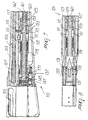
- FIG. 7 is a longitudinally sectioned, partial side view, of a gas-operated self-actuating firearm according to the invention;
- FIG. 8 is a top plan, longitudinally sectioned, view of the firearm of FIG. 7;
- FIG. 9 is an enlarged side, longitudinally sectioned, view of a detail of the cylinder of the firearm of FIGs. 7 and 8;
- FIG. 10 is a longitudinally sectioned side view of the front part of the firearm of FIGs. 7-9.
-
- Figures 1-6 illustrate a rifle, generally designated by the reference numeral 1, comprising a
barrel 3 having abore 5 connected to a firing chamber that accommodates acartridge 7 and that can be closed by abreechblock 9, in a per se known manner. The rifle illustrated in figures 1-6 does not form part of the scope of protection of claim 1. - The breechblock is actuated by a kinematic system which receives energy from the firing gases that arrive from a
gas tap 15, provided in thebarrel 3 and connecting thebore 5 of the barrel to aninternal chamber 11 of acylinder 13 which is associated with thebarrel 3 and is in turn provided with apassage 17, for the gas. - The
cylinder 13 comprises apiston 19 that can slide on apost 21 which is coaxial to thechamber 11 and has acylindrical block 23, at the opposite end with respect to thepiston 19. Thecylindrical block 23 protrudes at least partially from afront end 25 of thecylinder 13. - The
post 21 is crossed by anaxial passage 27 which is open onto the front part of theblock 23 and ends with aradial passage 53 at awider base 55 of thepost 21. - The
piston 19 has a first insidediameter 57, so that it can slide hermetically with respect to thewider base 55 of thepost 21, and has a second insidediameter 59, which is greater than the first diameter, so that in a stroke limit position, shown in FIG. 6, theradial passage 53 is open onto theinternal chamber 11 of thecylinder 13. - A
flat member 29 is rigidly associated with thepiston 19, externally to thecylinder 13, and comprises twoprotrusions 31 adapted to act onrespective pins 33 that are kinematically connected to the kinematic actuation system of thebreechblock 9. - The
pins 33 protrude from respectivelateral slots 35 formed in aplate 37 which closes aframe 39 of the firearm at the front. - The
plate 37 has acentral slot 41, crossed by abase 43 of thepost 21, which can be screwed into theframe 39. - The
slots plate 37 that can be lifted and extracted from thepins 33 and from thepost 21. - The
plate 37 is also provided with interlocking means for locking it on theframe 39. - The
plate 37 is also adapted to lock ahinge assembly 45 of amagazine 47 which is associated with theframe 39. - Each of the
pins 33 has astem 49 which is internal to theframe 39 and can slide in arespective guide 51 formed therein. The end of thestem 49 is adapted to make contact with a surface of thebreechblock 9. - The operation of the firearm is as follows.
- Initially, before firing, the
piston 19 is in an inactive position, shown in FIG. 5, in which theradial passage 53 is closed by the first insidediameter 57 of thepiston 19. - Upon firing, a fraction of the gases, generated by firing, passes into the
chamber 11 of thecylinder 13, through thegas intake 15 and thepassage 17, and pushes thepiston 19, which in turn acts, by means of theflat member 29 and theprotrusions 31, on thepins 33, that act on thebreechblock 9, causing its retraction, as shown in FIG. 6. - When the piston reaches the end of its stroke, which is determined by the abutment of the
flat member 29 against theplate 37, theradial passage 53 is located at the second insidediameter 59 of thepiston 19, and since the second insidediameter 59 is greater than the first insidediameter 57, it therefore connects thechamber 11 of thecylinder 13 to theaxial passage 27 of thepost 21, thus discharging the gases externally. - In the meantime, the kinematic system of the breechblock, by the action of the recocking spring, pushes the breechblock into the closure position and also pushes the
piston 19, by means of thepins 33, into an inactive position, ready for subsequent firing. - The system for discharging the excess gases through the
axial passage 27 is particularly advantageous, and keeps the component parts of the gas collection device clean, considerably reducing interventions for cleaning and maintenance. - Another important characteristic of the firearm is that the sleeve, or cylinder, 13 of the gas collection device is rigidly associated with the barrel, allowing to disassemble the barrel by sliding the lining off the
post 21, which can remain associated with theframe 39. - In such manner, the barrel can be disassembled rapidly and easily for ordinary cleaning and maintenance and also allows to maintain unchanged the setting of the sights.
- Another advantage, from the manufacturing point of view, is that it is possible to adapt the
gas collection chamber 11 to the caliber of the firearm during manufacture simply by replacing thepost 21, keeping unchanged all the other component parts of the gas collection device. The volume of thechamber 11 can in fact be adjusted simply by varying the diameter of thepost 21. - Another interesting feature is the
plate 37, which performs several tasks. First of all, it prevents the piston from directly striking theframe 39, which is generally made of aluminum alloy and is therefore more susceptible to damage. A second function of theplate 37 is to retain the magazine when the firearm has a pivoting magazine, of the kind shown in the figures of the present embodiment. Theplate 37 also retains thepins 33, preventing their loss when the barrel is disassembled. Once the barrel has been disassembled, thepiston 19 can in fact be slid off thepost 21. - The plate can be easily disassembled and reassembled, with a sliding motion, being interlocked with the
frame 39 and havingslots pins 33 and of thewider portions post 21. - Once the plate has been disassembled, the
pins 33 can be extracted from their respective seats in theframe 39 and also thepost 21 can be unscrewed and removed from the frame. - Figures 7-10 illustrate an embodiment of the invention constituted by a rifle, generally designated by the
reference numeral 101, comprising abarrel 103 having abore 105 connected to a firing chamber that accommodates acartridge 107 and that can be closed by abreechblock 109, in a per se known manner. - The
breechblock 109 is actuated by a kinematic system which receives energy from the firing gases that arrive from a gas tap 115, provided in thebarrel 103 and connecting thebore 105 of the barrel to aninternal chamber 111 of acylinder 113 which is associated with thebarrel 103 and is in turn provided with apassage 117, for the gas. - The
cylinder 113 comprises apiston 119 that can slide on apost 121 which is coaxial to thechamber 111 and has acylindrical block 123, at the opposite end with respect to thepiston 119. Thecylindrical block 123 protrudes, at least partially, from the front end of thecylinder 113 and extends into a front cylinder orcap 125. - An
axial passage 127 extends longitudinally in thepost 121 and is open on the front part of thecylindrical block 123 while, on the opposite side, ends into aradial passage 153 which connects theaxial passage 127 withchamber 111. -
Post 121 also has afront passage 159, connected withradial passage 153, and connectingchamber 111 with the outside, through a safety valve comprising aconical pin 160 and abias spring 161, both arranged in adischarge chamber 162 which is substantially insidefront cylinder 125. -
Discharge chamber 162 extends inside afastening cap 167 screwed on thefront cylinder 125 with the interposition of acontrast spring 166 which is substantially arranged inside the front portion of thedischarge chamber 162. -
Discharge chamber 162 is open to the outside through aradial vent 164 formed in fasteningcap 167. - A seal means is provided between
piston 119 and the inner surface ofcylinder 113 in order to improve the sliding ofpiston 119 inside the cylinder. - The seal means comprises external seal rings 171 and internal seal rings 172.
- The term "external" seal rings 171, in this case, identifies the rings that provide a seal on the cylinder surface while having a play with respect to the piston. The term "internal" seal rings 172 identifies rings that provide a seal with respect of the piston surface while having a play with respect to the cylinder.
- In such manner, the production of the seal means is simplified, because the tolerances are greatly simplified, and also the seal means are self-entering when assembling the parts.
-
Piston 119 is associated with a pair ofprotrusions 131 adapted to act on thebreechblock 109 of the firearm in a manner similar to the above described first embodiment. - The operation of the firearm illustrated in FIGs. 7-10 is substantially similar to that of the rifle illustrated in figures 1-6.
- A different feature of this embodiment, with respect of the rifle illustrated in figures 1-6, is that a plate, designated by the
reference numeral 137 in this embodiment, is provided in a position similar to that of theplate 37 of the rifle illustrated in figures 1-6. However,plate 137 is not provided with slots for its disassembly and does not have the function of retaining thehinge assembly 145 of the magazine as in the rifle illustrated in figures 1-6. -
Plate 145 has however the function of guiding the post on the front hole and is mounted by means of aSnap ring 177. - In practice it has been observed that the invention achieves the intended 30 aim and objects, a gas collection device for automatic or semiautomatic firearms having been provided which is particularly efficient and constructively simple.
- The device, according to the invention, is susceptible of numerous modifications and variations, within the scope of the appended claims, and all the details may be replaced with technically equivalent elements.
- The materials used, as well as the dimensions, may of course be any according to requirements and to the state of the art.
Claims (10)
- A self-actuating firearm, comprising a frame, a breechblock (109), a barrel (103) provided with a bore (105), a cylinder (113) associated with said barrel and forming an internal chamber (111) which is connected to the bore of the barrel, by means of a gas tap (115), and a piston (119) which is at least partially accommodated in said chamber and can be actuated by the gases that arrive from said bore upon firing of the firearm;
said firearm further comprising a post (121) which is rigidly coupled to said frame (39) and runs along the entire length of said cylinder (113) inside said chamber (111 ), said piston (119) being adapted to slide on said post, providing a seal between said post and the internal surface of said cylinder, said chamber being formed by the inner surface of said cylinder and by the outer surface of said post;
said piston floating with respect to said cylinder and said frame and comprising a portion which is external to said cylinder and is adapted to act with an impulsive action on said breechblock in order to recock the firearm upon firing;
a seal means (171, 172) being provided between said piston (119) and an inner surface of said cylinder (113), in order to improve the sliding of said piston inside said cylinder, said seal means comprising external seal rings (171) and internal seal rings (172), whereby said external seal rings (171) provide a seal on the cylinder surface while having a play with respect to the piston (119), said internal seal rings (172) providing a seal with respect of the piston surface while having a play with respect to the cylinder, in order to simplify the production of said seal means and in order to provide a self-centering of respecting parts of the firearm. - The self-actuating firearm according to claim 1, characterized in that it comprises a floating means (133) which floats with respect to said frame and is arranged between said outer portion of said piston and said breechblock; said floating means comprising two pins (103), each of said pins comprising a stem which can slide in a respective guide formed in said frame, a free end of the stem being adapted to make contact with a surface of the breechblock (109).
- The self-actuating firearm according to one or more of the preceding claims, characterized in that it comprises an axial passage (127) which is formed in said post (121) and is open outward at the front, said axial passage being alternately connected to said chamber (111) in order to vent the excess gases that are generated by firing and are fed to said chamber.
- The self-actuating firearm according to one or more of the preceding claims, characterized in that it comprises a pivoting magazine (147) which is associated with said frame by means of a hinge assembly (145), said plate being adapted to retain said hinge assembly of said magazine.
- The self-actuating firearm according to one or more of the preceding claims, characterized in that said post (121) comprises a cylindrical block (123), at the opposite end with respect to said piston (119), said cylindrical block protruding, at least partially, from the front end of the cylinder (113) and extending into a front cylinder or cap (125).
- The self-actuating firearm according to one or more of the preceding claims, characterized in that an axial passage (127) extends longitudinally in said post (121) and is open on the front part of said cylindrical block (123) while, on the opposite side, ends into a radial passage (153) which connects the axial passage (127) with said chamber (111).
- The self-actuating firearm according to one or more of the preceding claims, characterized in that said post (121) has a front passage (159), connected with said radial passage (153), and connecting said chamber (111) with the outside, through a safety valve (160,161).
- The self-actuating firearm according to one or more of the preceding claims, characterized in that said safety valve comprises a conical pin (160) and a bias spring (161), both arranged in a discharge chamber (162) which is substantially inside said front cylinder (125).
- The self-actuating firearm according to one or more of the preceding claims, characterized in that said discharge chamber (162) extends inside a fastening cap (167), screwed on said front cylinder (125), with the interposition of a contrast spring (166) which is substantially arranged inside the front portion of said discharge chamber (162), said discharge chamber being open to the outside through a radial vent (164) formed in said fastening cap (167).
- The self-actuating firearm according to one or more of the preceding claims, characterized in that it comprises a plate (137) adapted to guide said post on the front hole and being mounted by means of a snap ring (177).
Priority Applications (2)
| Application Number | Priority Date | Filing Date | Title |
|---|---|---|---|
| DK01128118T DK1215464T3 (en) | 2000-12-14 | 2001-11-27 | Self-loading firearms |
| SI200130335T SI1215464T1 (en) | 2000-12-14 | 2001-11-27 |
Applications Claiming Priority (2)
| Application Number | Priority Date | Filing Date | Title |
|---|---|---|---|
| IT2000MI002700A IT1319535B1 (en) | 2000-12-14 | 2000-12-14 | REPEAT FIREARM |
| ITMI002700 | 2000-12-14 |
Publications (2)
| Publication Number | Publication Date |
|---|---|
| EP1215464A1 EP1215464A1 (en) | 2002-06-19 |
| EP1215464B1 true EP1215464B1 (en) | 2005-03-30 |
Family
ID=11446230
Family Applications (1)
| Application Number | Title | Priority Date | Filing Date |
|---|---|---|---|
| EP01128118A Expired - Lifetime EP1215464B1 (en) | 2000-12-14 | 2001-11-27 | Self-actuating firearm |
Country Status (11)
| Country | Link |
|---|---|
| US (1) | US6619592B2 (en) |
| EP (1) | EP1215464B1 (en) |
| JP (1) | JP3669957B2 (en) |
| AT (1) | ATE292271T1 (en) |
| BR (1) | BR0106137B1 (en) |
| DE (1) | DE60109718T2 (en) |
| DK (1) | DK1215464T3 (en) |
| ES (1) | ES2236119T3 (en) |
| IT (1) | IT1319535B1 (en) |
| PT (1) | PT1215464E (en) |
| SI (1) | SI1215464T1 (en) |
Cited By (8)
| Publication number | Priority date | Publication date | Assignee | Title |
|---|---|---|---|---|
| US7946214B2 (en) | 2007-08-29 | 2011-05-24 | Ra Brands, L.L.C. | Gas system for firearms |
| US8061260B2 (en) | 2009-06-22 | 2011-11-22 | Ra Brands, L.L.C. | Gas plug retention and removal device |
| US8065949B1 (en) | 2006-05-24 | 2011-11-29 | Remington Arms Company, Inc. | Gas-operated firearm |
| US8109194B2 (en) | 2009-03-20 | 2012-02-07 | Ra Brands, L.L.C. | Clamped gas block for barrel |
| USD661364S1 (en) | 2010-06-21 | 2012-06-05 | Ra Brands, L.L.C. | Gas block |
| US8250964B2 (en) | 2007-08-29 | 2012-08-28 | Ra Brands, L.L.C. | Gas system for firearms |
| US9347719B1 (en) | 2014-01-13 | 2016-05-24 | Ra Brands, L.L.C. | Replaceable feed ramp |
| US9383154B2 (en) | 2013-12-12 | 2016-07-05 | Ra Brands, L.L.C. | Gas vent for firearm |
Families Citing this family (34)
| Publication number | Priority date | Publication date | Assignee | Title |
|---|---|---|---|---|
| US6634274B1 (en) * | 2000-12-11 | 2003-10-21 | Geoffrey Andrew Herring | Firearm upper receiver assembly with ammunition belt feeding capability |
| ITMI20030458A1 (en) * | 2003-03-11 | 2004-09-12 | Bresciana Armi Fabarm | LOADING DEVICE FOR A SEMI-AUTOMATIC SPEARGUN. |
| US7448307B1 (en) * | 2005-09-30 | 2008-11-11 | Vesselin Dafinov | Gas operated semi-automatic rifle |
| BE1016821A3 (en) * | 2005-10-25 | 2007-07-03 | Browning Int Sa | IMPROVED SEMI-AUTOMATIC RIFLE |
| US7891284B1 (en) * | 2007-06-06 | 2011-02-22 | Christopher Gene Barrett | Firearm with gas system accessory latch |
| EP2141436A3 (en) * | 2008-07-01 | 2013-07-31 | Adcor Industries, Inc. | Operating handle for a firearm |
| US8210090B2 (en) * | 2008-07-01 | 2012-07-03 | Adcor Industries, Inc. | Firearm having an expulsion device |
| US8210089B2 (en) * | 2008-07-01 | 2012-07-03 | Adcor Industries, Inc. | Firearm having an indirect gas impingement system |
| US8141285B2 (en) | 2008-07-01 | 2012-03-27 | Adcor Industries, Inc. | Firearm including improved hand guard |
| US8245625B2 (en) * | 2008-07-29 | 2012-08-21 | Winge Michael L | Gas pressure mechanism in gas-operated firearm |
| US8393107B2 (en) | 2008-08-26 | 2013-03-12 | Adcor Industries, Inc. | Firearm assembly including a first weapon and a second weapon selectively mounted to the first weapon |
| US20100218671A1 (en) * | 2008-12-30 | 2010-09-02 | Magpul Industries Corporation | Adjustable and Suppressible Gas Operating System for an Automatic Firearm |
| US8176837B1 (en) | 2009-10-11 | 2012-05-15 | Jason Stewart Jackson | Firearm operating rod |
| US8640598B1 (en) | 2010-07-19 | 2014-02-04 | Jason Stewart Jackson | Sleeve piston for actuating a firearm bolt carrier |
| US9261314B1 (en) | 2010-07-19 | 2016-02-16 | Jason Stewart Jackson | Sleeve piston for actuating a firearm bolt carrier |
| DE202010012832U1 (en) * | 2010-09-18 | 2010-12-23 | Nobilta-TWM GbR / Lauster, Peter u. Bratz, Volker (vertretungsberechtigter Gesellschafter: Herr Volker Bratz, 78669 Wellendingen-Wilfingen) | Piston for direct and indirect gas pressure control |
| US8899138B2 (en) | 2011-09-08 | 2014-12-02 | Adcor Industries, Inc. | Firearm having a handle assembly for charging and forward assist |
| US9003686B2 (en) | 2012-02-13 | 2015-04-14 | Adcor Industries, Inc. | Hand guard mounting mechanism |
| US8997620B2 (en) | 2012-03-09 | 2015-04-07 | Adcor Industries, Inc. | Handle assembly for charging a direct gas impingement firearm |
| US8893608B2 (en) * | 2012-07-03 | 2014-11-25 | Lawrence S. Kramer | Gas piston system for M16/AR15 rifle or M4 carbine systems |
| US9097475B2 (en) * | 2012-12-05 | 2015-08-04 | Ra Brands, L.L.C. | Gas-operated firearm with pressure compensating gas piston |
| US9243859B1 (en) * | 2014-01-16 | 2016-01-26 | FN America, LLC | Gas block valve stem for modifying the firing rate of a machine gun |
| US9816769B1 (en) * | 2016-10-25 | 2017-11-14 | Ambimjb, Llc | Gas piston firearm system and method |
| US20180142974A1 (en) * | 2016-11-18 | 2018-05-24 | Ra Brands, L.L.C. | Gas operating system with exhaust system |
| AU2017378996B2 (en) | 2016-12-19 | 2024-02-08 | Savage Arms, Inc. | Semi-automatic shotgun and components thereof |
| US11879700B2 (en) | 2016-12-19 | 2024-01-23 | Savage Arms, Inc. | Semi-automatic shotgun and components thereof |
| US10274273B1 (en) * | 2017-05-30 | 2019-04-30 | Garrett Weston Potter | Process of making a gas operated firearm barrel |
| US10386140B2 (en) * | 2017-06-12 | 2019-08-20 | Kramer Cartridge & Carbine LLC | Direct gas impingement system |
| US10422596B2 (en) * | 2017-06-12 | 2019-09-24 | Kramer Cartridge & Carbine LLC | Bolt carrier group for direct gas impingement system |
| US10852084B2 (en) * | 2018-06-15 | 2020-12-01 | Michael Gregorich | Advanced gas piston system |
| DE102019102660A1 (en) | 2019-02-04 | 2020-08-06 | Rheinmetall Waffe Munition Gmbh | Gas pistons and weapon |
| US10753692B1 (en) * | 2019-02-27 | 2020-08-25 | Robert B. Thompson | Hybrid gas-piston rifle and barrel nut |
| US11280567B1 (en) | 2019-11-25 | 2022-03-22 | Heckler & Koch Inc. | Adjustable gas piston action firearm |
| FI129283B (en) * | 2020-10-29 | 2021-11-15 | Kavahda Oy | Gun with a delay function |
Family Cites Families (7)
| Publication number | Priority date | Publication date | Assignee | Title |
|---|---|---|---|---|
| US2149512A (en) * | 1937-08-06 | 1939-03-07 | Eiane Halvor Olsen | Automatic gun |
| US2582989A (en) * | 1948-05-06 | 1952-01-22 | Earle M Harvey | Gas piston for firearms |
| US3657960A (en) | 1970-06-12 | 1972-04-25 | Olin Corp | Self aligning gas system for firearm |
| JPS512238B1 (en) | 1971-04-21 | 1976-01-23 | ||
| US4409883A (en) * | 1981-06-03 | 1983-10-18 | Edouard Nyst | Gas operated firearm |
| IT1282015B1 (en) | 1996-02-08 | 1998-03-06 | Benelli Armi Spa | AUTOMATIC GAS-HOLDED WEAPON |
| IT1311772B1 (en) * | 1999-12-10 | 2002-03-19 | Beretta Armi Spa | SPEARGUN WITH PERFECTED GAS SOCKET. |
-
2000
- 2000-12-14 IT IT2000MI002700A patent/IT1319535B1/en active
-
2001
- 2001-11-27 PT PT01128118T patent/PT1215464E/en unknown
- 2001-11-27 AT AT01128118T patent/ATE292271T1/en active
- 2001-11-27 DE DE60109718T patent/DE60109718T2/en not_active Expired - Lifetime
- 2001-11-27 SI SI200130335T patent/SI1215464T1/xx unknown
- 2001-11-27 EP EP01128118A patent/EP1215464B1/en not_active Expired - Lifetime
- 2001-11-27 DK DK01128118T patent/DK1215464T3/en active
- 2001-11-27 ES ES01128118T patent/ES2236119T3/en not_active Expired - Lifetime
- 2001-11-27 US US09/995,115 patent/US6619592B2/en not_active Expired - Lifetime
- 2001-12-07 JP JP2001373568A patent/JP3669957B2/en not_active Expired - Fee Related
- 2001-12-14 BR BRPI0106137-2A patent/BR0106137B1/en not_active IP Right Cessation
Cited By (9)
| Publication number | Priority date | Publication date | Assignee | Title |
|---|---|---|---|---|
| US8065949B1 (en) | 2006-05-24 | 2011-11-29 | Remington Arms Company, Inc. | Gas-operated firearm |
| US7946214B2 (en) | 2007-08-29 | 2011-05-24 | Ra Brands, L.L.C. | Gas system for firearms |
| US8250964B2 (en) | 2007-08-29 | 2012-08-28 | Ra Brands, L.L.C. | Gas system for firearms |
| US8109194B2 (en) | 2009-03-20 | 2012-02-07 | Ra Brands, L.L.C. | Clamped gas block for barrel |
| US8061260B2 (en) | 2009-06-22 | 2011-11-22 | Ra Brands, L.L.C. | Gas plug retention and removal device |
| USD661364S1 (en) | 2010-06-21 | 2012-06-05 | Ra Brands, L.L.C. | Gas block |
| US9383154B2 (en) | 2013-12-12 | 2016-07-05 | Ra Brands, L.L.C. | Gas vent for firearm |
| US9347719B1 (en) | 2014-01-13 | 2016-05-24 | Ra Brands, L.L.C. | Replaceable feed ramp |
| US9562730B2 (en) | 2014-01-13 | 2017-02-07 | Ra Brands, L.L.C. | Replaceable feed ramp |
Also Published As
| Publication number | Publication date |
|---|---|
| DE60109718D1 (en) | 2005-05-04 |
| US20020073832A1 (en) | 2002-06-20 |
| SI1215464T1 (en) | 2005-08-31 |
| BR0106137A (en) | 2002-08-13 |
| ES2236119T3 (en) | 2005-07-16 |
| JP2002195792A (en) | 2002-07-10 |
| BR0106137B1 (en) | 2010-08-24 |
| DE60109718T2 (en) | 2005-09-15 |
| ITMI20002700A1 (en) | 2002-06-14 |
| IT1319535B1 (en) | 2003-10-20 |
| US6619592B2 (en) | 2003-09-16 |
| JP3669957B2 (en) | 2005-07-13 |
| ATE292271T1 (en) | 2005-04-15 |
| EP1215464A1 (en) | 2002-06-19 |
| PT1215464E (en) | 2005-06-30 |
| DK1215464T3 (en) | 2005-04-25 |
Similar Documents
| Publication | Publication Date | Title |
|---|---|---|
| EP1215464B1 (en) | Self-actuating firearm | |
| US4901623A (en) | Compensating device for gas actuated firearms | |
| US4709617A (en) | Firearm | |
| EP1586846B1 (en) | Pistol with loaded chamber indicator | |
| US8312656B2 (en) | Shotgun having an improved shotshell feeding mechanism | |
| US10247500B2 (en) | Modular bolt assembly with floating fire pin | |
| US20120023800A1 (en) | Unitary breechblock assembly | |
| US11852427B2 (en) | Firearm | |
| US7987763B1 (en) | Double action firing pin system | |
| FI72599B (en) | ETT GEVAER MED OEVERFLYTTNING AV GAS. | |
| US4407085A (en) | Handgun firing mechanism | |
| US3090148A (en) | Bolt action firearm with charger | |
| US10018433B2 (en) | Linear locking barrel system for firearm | |
| EA006893B1 (en) | Firearm with a readily interchangeable bolt face | |
| US4705200A (en) | Pivot-load powder actuated tool with firing chamber insert | |
| US2548622A (en) | Firing mechanism for submachine guns | |
| EP3407002A1 (en) | Pellet loading system | |
| US11592248B2 (en) | Hybrid gas-piston rifle and barrel nut | |
| RU2276315C2 (en) | Breechblock of multifiring weapon | |
| EP1106955B1 (en) | Firearm having inertia striker mechanism | |
| US3680433A (en) | Semi-automatic shotgun having rotary and sliding breech block | |
| US2504162A (en) | Firing mechanism | |
| US7275342B2 (en) | Semi-automatic weapon for several tubes cartridges loading system for long guns | |
| US2765559A (en) | Carrier mechanism for guns | |
| US3424053A (en) | Automatic firearm |
Legal Events
| Date | Code | Title | Description |
|---|---|---|---|
| PUAI | Public reference made under article 153(3) epc to a published international application that has entered the european phase |
Free format text: ORIGINAL CODE: 0009012 |
|
| AK | Designated contracting states |
Kind code of ref document: A1 Designated state(s): AT BE CH CY DE DK ES FI FR GB GR IE IT LI LU MC NL PT SE TR |
|
| AX | Request for extension of the european patent |
Free format text: AL;LT;LV;MK;RO;SI |
|
| 17P | Request for examination filed |
Effective date: 20020809 |
|
| 17Q | First examination report despatched |
Effective date: 20021007 |
|
| AKX | Designation fees paid |
Designated state(s): AT BE CH CY DE DK ES FI FR GB GR IE IT LI LU MC NL PT SE TR |
|
| AXX | Extension fees paid |
Extension state: MK Payment date: 20020809 Extension state: SI Payment date: 20020809 Extension state: RO Payment date: 20020809 Extension state: LT Payment date: 20020809 Extension state: LV Payment date: 20020809 Extension state: AL Payment date: 20020809 |
|
| GRAP | Despatch of communication of intention to grant a patent |
Free format text: ORIGINAL CODE: EPIDOSNIGR1 |
|
| GRAS | Grant fee paid |
Free format text: ORIGINAL CODE: EPIDOSNIGR3 |
|
| GRAA | (expected) grant |
Free format text: ORIGINAL CODE: 0009210 |
|
| AK | Designated contracting states |
Kind code of ref document: B1 Designated state(s): AT BE CH CY DE DK ES FI FR GB GR IE IT LI LU MC NL PT SE TR |
|
| AX | Request for extension of the european patent |
Extension state: AL LT LV MK RO SI |
|
| REG | Reference to a national code |
Ref country code: GB Ref legal event code: FG4D |
|
| REG | Reference to a national code |
Ref country code: CH Ref legal event code: EP |
|
| REG | Reference to a national code |
Ref country code: SE Ref legal event code: TRGR |
|
| REG | Reference to a national code |
Ref country code: DK Ref legal event code: T3 |
|
| REF | Corresponds to: |
Ref document number: 60109718 Country of ref document: DE Date of ref document: 20050504 Kind code of ref document: P |
|
| REG | Reference to a national code |
Ref country code: IE Ref legal event code: FG4D |
|
| REG | Reference to a national code |
Ref country code: GR Ref legal event code: EP Ref document number: 20050401111 Country of ref document: GR |
|
| REG | Reference to a national code |
Ref country code: CH Ref legal event code: NV Representative=s name: KEMENY AG PATENTANWALTBUERO |
|
| REG | Reference to a national code |
Ref country code: PT Ref legal event code: SC4A Free format text: AVAILABILITY OF NATIONAL TRANSLATION Effective date: 20050503 |
|
| REG | Reference to a national code |
Ref country code: ES Ref legal event code: FG2A Ref document number: 2236119 Country of ref document: ES Kind code of ref document: T3 |
|
| PLBE | No opposition filed within time limit |
Free format text: ORIGINAL CODE: 0009261 |
|
| STAA | Information on the status of an ep patent application or granted ep patent |
Free format text: STATUS: NO OPPOSITION FILED WITHIN TIME LIMIT |
|
| ET | Fr: translation filed | ||
| 26N | No opposition filed |
Effective date: 20060102 |
|
| REG | Reference to a national code |
Ref country code: CH Ref legal event code: PFA Owner name: BENELLI ARMI S.P.A. Free format text: BENELLI ARMI S.P.A.#VIA DELLA STAZIONE, 50#I-61029 URBINO(PESARO) (IT) -TRANSFER TO- BENELLI ARMI S.P.A.#VIA DELLA STAZIONE, 50#I-61029 URBINO(PESARO) (IT) |
|
| REG | Reference to a national code |
Ref country code: FR Ref legal event code: PLFP Year of fee payment: 15 |
|
| REG | Reference to a national code |
Ref country code: FR Ref legal event code: PLFP Year of fee payment: 16 |
|
| PGFP | Annual fee paid to national office [announced via postgrant information from national office to epo] |
Ref country code: CH Payment date: 20160928 Year of fee payment: 16 Ref country code: IE Payment date: 20160920 Year of fee payment: 16 |
|
| PGFP | Annual fee paid to national office [announced via postgrant information from national office to epo] |
Ref country code: GR Payment date: 20160920 Year of fee payment: 16 Ref country code: PT Payment date: 20160919 Year of fee payment: 16 Ref country code: SE Payment date: 20160922 Year of fee payment: 16 |
|
| PGFP | Annual fee paid to national office [announced via postgrant information from national office to epo] |
Ref country code: LU Payment date: 20161006 Year of fee payment: 16 |
|
| PGFP | Annual fee paid to national office [announced via postgrant information from national office to epo] |
Ref country code: FI Payment date: 20161107 Year of fee payment: 16 Ref country code: MC Payment date: 20161130 Year of fee payment: 16 Ref country code: DK Payment date: 20161101 Year of fee payment: 16 Ref country code: CY Payment date: 20161003 Year of fee payment: 16 Ref country code: NL Payment date: 20161108 Year of fee payment: 16 |
|
| PGFP | Annual fee paid to national office [announced via postgrant information from national office to epo] |
Ref country code: AT Payment date: 20161108 Year of fee payment: 16 Ref country code: ES Payment date: 20161005 Year of fee payment: 16 |
|
| REG | Reference to a national code |
Ref country code: FR Ref legal event code: PLFP Year of fee payment: 17 |
|
| PGFP | Annual fee paid to national office [announced via postgrant information from national office to epo] |
Ref country code: SE Payment date: 20160922 Year of fee payment: 16 |
|
| REG | Reference to a national code |
Ref country code: DE Ref legal event code: R082 Ref document number: 60109718 Country of ref document: DE Representative=s name: BRINKMANN & PARTNER PATENTANWAELTE PARTNERSCHA, DE Ref country code: DE Ref legal event code: R082 Ref document number: 60109718 Country of ref document: DE Representative=s name: RAUSCH WANISCHECK-BERGMANN BRINKMANN PARTNERSC, DE |
|
| REG | Reference to a national code |
Ref country code: DK Ref legal event code: EBP Effective date: 20171130 |
|
| PG25 | Lapsed in a contracting state [announced via postgrant information from national office to epo] |
Ref country code: MC Free format text: LAPSE BECAUSE OF NON-PAYMENT OF DUE FEES Effective date: 20171130 |
|
| REG | Reference to a national code |
Ref country code: SE Ref legal event code: EUG |
|
| REG | Reference to a national code |
Ref country code: NL Ref legal event code: MM Effective date: 20171201 |
|
| REG | Reference to a national code |
Ref country code: AT Ref legal event code: MM01 Ref document number: 292271 Country of ref document: AT Kind code of ref document: T Effective date: 20171127 |
|
| PG25 | Lapsed in a contracting state [announced via postgrant information from national office to epo] |
Ref country code: CY Free format text: LAPSE BECAUSE OF NON-PAYMENT OF DUE FEES Effective date: 20171127 Ref country code: LI Free format text: LAPSE BECAUSE OF NON-PAYMENT OF DUE FEES Effective date: 20171130 Ref country code: CH Free format text: LAPSE BECAUSE OF NON-PAYMENT OF DUE FEES Effective date: 20171130 Ref country code: FI Free format text: LAPSE BECAUSE OF NON-PAYMENT OF DUE FEES Effective date: 20171127 Ref country code: PT Free format text: LAPSE BECAUSE OF NON-PAYMENT OF DUE FEES Effective date: 20180528 |
|
| PG25 | Lapsed in a contracting state [announced via postgrant information from national office to epo] |
Ref country code: LU Free format text: LAPSE BECAUSE OF NON-PAYMENT OF DUE FEES Effective date: 20171127 Ref country code: SE Free format text: LAPSE BECAUSE OF NON-PAYMENT OF DUE FEES Effective date: 20171128 Ref country code: AT Free format text: LAPSE BECAUSE OF NON-PAYMENT OF DUE FEES Effective date: 20171127 Ref country code: GR Free format text: LAPSE BECAUSE OF NON-PAYMENT OF DUE FEES Effective date: 20180604 |
|
| REG | Reference to a national code |
Ref country code: SI Ref legal event code: KO00 Effective date: 20180709 |
|
| REG | Reference to a national code |
Ref country code: IE Ref legal event code: MM4A |
|
| PG25 | Lapsed in a contracting state [announced via postgrant information from national office to epo] |
Ref country code: IE Free format text: LAPSE BECAUSE OF NON-PAYMENT OF DUE FEES Effective date: 20171127 Ref country code: NL Free format text: LAPSE BECAUSE OF NON-PAYMENT OF DUE FEES Effective date: 20171201 |
|
| REG | Reference to a national code |
Ref country code: FR Ref legal event code: PLFP Year of fee payment: 18 |
|
| PG25 | Lapsed in a contracting state [announced via postgrant information from national office to epo] |
Ref country code: DK Free format text: LAPSE BECAUSE OF NON-PAYMENT OF DUE FEES Effective date: 20171130 |
|
| PG25 | Lapsed in a contracting state [announced via postgrant information from national office to epo] |
Ref country code: ES Free format text: LAPSE BECAUSE OF NON-PAYMENT OF DUE FEES Effective date: 20171128 |
|
| PGFP | Annual fee paid to national office [announced via postgrant information from national office to epo] |
Ref country code: TR Payment date: 20201002 Year of fee payment: 20 |
|
| PGFP | Annual fee paid to national office [announced via postgrant information from national office to epo] |
Ref country code: IT Payment date: 20200925 Year of fee payment: 20 Ref country code: GB Payment date: 20201005 Year of fee payment: 20 Ref country code: DE Payment date: 20201030 Year of fee payment: 20 Ref country code: FR Payment date: 20201021 Year of fee payment: 20 |
|
| PGFP | Annual fee paid to national office [announced via postgrant information from national office to epo] |
Ref country code: BE Payment date: 20201014 Year of fee payment: 20 |
|
| REG | Reference to a national code |
Ref country code: DE Ref legal event code: R071 Ref document number: 60109718 Country of ref document: DE |
|
| REG | Reference to a national code |
Ref country code: GB Ref legal event code: PE20 Expiry date: 20211126 |
|
| REG | Reference to a national code |
Ref country code: BE Ref legal event code: MK Effective date: 20211127 |
|
| PG25 | Lapsed in a contracting state [announced via postgrant information from national office to epo] |
Ref country code: GB Free format text: LAPSE BECAUSE OF EXPIRATION OF PROTECTION Effective date: 20211126 |