Technical Field
The present invention relates to a valve provided
in a gas flow path in which a gas containing,
especially, at least one of corrosive gas and fine
particle is allowed to flow, and a vacuum processing
apparatus comprising the valve, and more specifically,
to a valve having an excellent anti-corrosive property,
and a high durability in function, and a vacuum
processing apparatus comprising the valve.
Background Art
In semiconductor factories, a great number of
process gases are employed to process objects to be
processed, such as semiconductor wafers. Further, gas
pipes for feeding such process gases are provided with
various types of valves for controlling the flow
amounts of such gases. Note that each valve is used
also as open/close means for opening/closing a
connection path between chambers which constitute the
vacuum processing apparatus.
The connection path connecting a processing
chamber where a processing using a gas is carried out,
to another chamber, and the gas flow path such as a gas
pipe are exposed to gas in a great number of occasions.
Therefore, especially when a gas having a corrosive
property is used, there are various anti-corrosive
measures are taken, such as that the section which
constitutes the gas flow path is made of an anti-corrosive
material.
FIG. 8 is a schematic diagram showing a part of
a conventional vacuum processing apparatus which
carries out a film formation process or etching process
on an object to be processed, such as a semiconductor
wafer. As shown in this figure, a vacuum processing
apparatus A includes a processing chamber 1 for
carrying out a predetermined processing on an object W
to be processed with use of a gas under a predetermined
vacuum atmosphere, a plurality of gas supplying pipes 2
and a gas exhaustion pipe 3, both connected to the
processing chamber 1, and a valve 4 mounted on the gas
exhaustion pipe 3. In the processing apparatus A
described above, a plurality of kinds of process gases
are supplied into the processing chamber 1 from these
plurality of gas supplying pipes 2, and a predetermined
process is carried out on the object W to be processed
in the processing chamber 1. Further, unreacted gases,
reaction byproducts and the like in the processing
chamber 1 are exhausted from the processing chamber 1
via the gas exhaustion pipe 3. In this case, the flow
of the exhaustion of the gas is controlled by the
valve 4. Further, in many cases, a corrosive gas is
used as the process gas, and therefore the gas flow
paths for the processing chamber 1, the gas supplying
pipe 2 and the gas exhaustion pipe 3 are treated
completely to make it corrosion proof.
The valve 4 includes a valve main body, a valve
member for opening/closing the gas flow path in the
main body, a drive mechanism for driving the valve
member and a sealing mechanism for isolating air-tightly
the drive mechanism side from the valve
drive mechanism. In this case, an anti-corrosive
countermeasure is taken for the valve main body part
which constitutes the gas flow path, but the sealing
mechanism is not subjected to the anti-corrosive
provisions. (Naturally, no anti-corrosive measures are
taken for the drive mechanism.)
As described above, in the conventional valve, the
anti-corrosive measures are not taken for the sealing
mechanism, and therefore the seal mechanism is corroded
with corrosive gases such as process gas and reaction
byproducts. As a result, there is a danger of vacuum
break caused from a corroded section of the sealing
mechanism. Further, the reaction byproducts flowing
through the gas exhaustion pipe 3 contains particles,
and the seal mechanism may clog with some of the
particles, thereby causing an operational error of
the valve member or vacuum break.
Disclosure of Invention
An object of the present invention is to provide
valve which can certainly prevent corrosion of
a sealing mechanism for sealing a valve main body
air-tightly with respect to a drive mechanism side, as
well as the drive mechanism, and further can certainly
prevent an operational error caused by particles
contained in gas, thereby achieving a gas leakage
proof and vacuum break proof, and a vacuum processing
apparatus comprising such a valve.
The above-described object can be achieved by the
following valve. That is, a valve comprising: a valve
main body having an opening and forming a space which
creates a part of a gas flow path; a first valve
member, provided in the valve main body, for
opening/closing the opening; and a drive mechanism,
provided outside the valve main body, for moving the
first valve member between a close position where
the opening is closed and an open position where the
opening is opened, wherein the drive mechanism has
a rod to be reciprocated, an end of the rod extends
into the valve main body through a through hole formed
in the valve main body to be connected to the first
valve member, the first valve member is moved between
the close position and the open position as the rod is
reciprocated, the valve further comprising: a sealing
mechanism, which communicates into the valve main body
via the through hole, for isolating the drive mechanism
side air-tightly from the valve main body; and a second
valve member, provided on the rod to move together with
the rod as it is reciprocated, which closes the through
hole when the first valve member is situated at the
open or close position so as to isolate the sealing
mechanism with respect to the valve main body.
Brief Description of Drawings
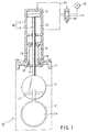
FIG. 1 is a partial cross sectional view of
a valve according to the first embodiment of the
present invention;
FIG. 2 is a schematic structural diagram showing
a vacuum processing apparatus to which the valve shown
in FIG. 1 is applied;
FIG. 3 is a plan view showing a remodeled version
of a second valve member;
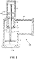
FIG. 4 is a partial cross sectional view of
a valve according to the second embodiment of the
present invention;
FIG. 5 is a partial cross sectional view of
a valve according to the third embodiment of the
present invention;
FIG. 6 is a partial cross sectional view of
a valve according to the fourth embodiment of the
present invention;
FIG. 7 is a partial cross sectional view of
a valve according to the fifth embodiment of the
present invention; and
FIG. 8 is a conceptual diagram showing a general
processing apparatus for semiconductor wafers and the
like.
Best Mode for Carrying Out of the Invention
Embodiments of the present invention will now be
described with reference to the drawings.
FIGS. 1 and 2 show the first embodiment of the
present invention. As shown in FIG. 2, a vacuum
processing apparatus B of this embodiment includes a
processing chamber 30 for carrying out a predetermined
processing on an object W to be processed with use of
a process gas under a predetermined vacuum atmosphere,
a plurality of gas supplying pipes 32 and a gas
exhaustion pipe 33, both connected to the processing
chamber 30, and a valve 10 mounted on the gas
exhaustion pipe 33. The processing chamber 30 is
connected to another chamber, which is not shown, such
as a transfer chamber. The gas supplying pipe 32 is
connected to a gas supplying source 34 for supplying
the process gas. Further, the gas exhaustion pipe 33
is connected to the vacuum pump 35.
In the processing apparatus B described above,
a process gas is supplied into the processing chamber
30 from the gas supplying source 34 via the gas
supplying tube 32, and a predetermined process is
carried out on the object W to be processed in the
processing chamber 30. Unreacted gases and reaction
byproducts and the like in the processing chamber 30
are exhausted from the processing chamber 30 via the
gas exhaustion pipe 33 by a suction force of the vacuum
pump 35. In this case, the amount of the flow of the
gas exhaustion is controlled by means of the valve 10.
As shown in FIG. 1, the valve 10 includes a valve
main body 11 of, for example, a rectangular shape
having a gas inlet/outlet 11A to which the gas
exhaustion pipe 33 is connected, a first valve member
12 which moves up and down within an inner space of
the valve main body 11 which forms a gas flow path so
as to open and close the gas inlet/outlet 11A, a drive
mechanism 40 for moving the first valve member 12 up
and down, and bellows 15 serving as a sealing mechanism
for isolating air-tightly the drive mechanism 40 from
the valve main body 11.
The drive mechanism 40 is comprised of a cylinder
housing 13 connected to the valve main body 11 and
a piston rod 14 which is connected to the first valve
member 12 and reciprocated by a pressure of air
supplied into the cylinder housing 13. Air is supplied
into the cylinder housing 13 from a pressure source 42
via an air supplying pipe path 43. In this case, the
supply of air to the bottom-side chamber C1 of the
cylinder housing 13, and the head-side chamber C2 is
switched by a direction switching valve 44 inserted to
the air supplying pipe path 43.
The cylinder housing 13 includes a housing chamber
16 partitioned from the bottom-side chamber C1 and the
head-side chamber C2. Further, the valve main body 11
has a through hole 11B for communicating the internal
space of the valve main body 11 to the internal space
of the housing chamber 16. The piston rod 14 extends
from an inside of the head-side chamber C2 into the
housing chamber 16, and also extends into the valve
main body 11 via the through hole 11B of the valve main
body 11. At an end of the piston rod 14 located in
the valve main body 11, the first valve member 12 is
mounted.
The bellows 15 are housed in the housing chamber
16 of the cylinder housing 13. Further, an upper end
of the bellows 15 is coupled to the rod 14, and a lower
end is coupled and fixed to a mount member 16A provided
on an outer surface site of the valve main body 11.
The bellows expand and contract along with the
reciprocation of the piston rod 14. Further, the
bellows 15 are provided such as to close the thorough
hole 11B (that is, to close the gap between the rod 14
and the through hole 11B), thus forming a partition
wall between the housing chamber 16 and the valve main
body 11. In this manner, the air-tightness inside
the valve main body 11 is maintained, and the drive
mechanism 40 side and the valve main body 11 are air
tightly enclosed from each other.
In order to prevent the bellows 15 from being
corroded with corrosive gas flowing in the valve main
body 11, a second valve member 17 is fixedly mounted on
the piston rod 14 so as to close the through hole 11B
thus isolating the bellows 15 from the valve main body
11 side. The second valve member 17 is made of a plate
of a predetermined shape (for example, a round shape),
and moves along with the motion of the first valve
member 12 for opening/closing the gas inlet/outlet 11A
(that is, the reciprocation of the piston rod 14), so
as to open/close the through hole 11B. More specifically,
the second valve member 17 closes the through
hole 11B by attaching to the inner surface of the upper
end portion of the valve main body 11 when the gas
inlet/outlet 11A is opened by the first valve member
12, thus preventing the process gas flowing in the
valve main body 11 from reaching the bellows 15 side.
It should be noted that a ring-formed groove 12C
is made in the inner surface of the upper end portion
of the valve main body 11 such as to surround the
through hole 11B, and an 0-ring 18 is fit in the groove
11C. With this structure, when the second valve member
17 is tightly attached to the inner surface of the
upper end of the valve main body 11, the through hole
11B is air-tightly closed by means of the 0-ring 18,
and thus the bellows 15 are surely isolated from the
valve main body 11 side.
Next, the operation of the valve 10 having the
above-described structure will now be described.
First, as air is supplied from the pressure source
42 to the head-side chamber C2 of the cylinder housing
13 via the air supplying pipe path 43, the piston
rod 14 contracts and thus the valve 10 of the gas
exhaustion pipe 33 is opened. More specifically, when
the piston rod 14 contracts, the first valve member 12
mounted on the piston rod 14 moves to the open position
indicated by a solid line from the close position
indicated by a one-dot dashed line shown in FIG. 1, and
thus the gas inlet/outlet 11A of the valve main body 11
is opened. In other words, the internal space of the
valve main body 11 and the gas exhaustion pipe 33 are
communicated with each other. Further, when the first
valve member 12 is moved to the open position, the
second valve member 17 mounted on the piston rod 14
moves to the close position indicated by a solid line
from the open position indicated by a one-dot dashed
line shown in FIG. 1, and thus the through hole 11B of
the valve main body 11 is air-tightly closed.
Then, while maintaining the above-described state,
the inside of the processing chamber 30 is evacuated
to a predetermined degree of vacuum. After that, a
process gas is supplied from the gas supplying source
34 into the processing chamber 30 via the gas supplying
pipe 32, and a predetermined process is carried out on
the object W to be processed in the processing chamber
30. At the same time, unreacted process gas, and gases
of reaction byproducts and the like, and particles are
exhausted from the processing chamber 30 via the gas
exhaustion pipe 33, and therefore they pass within the
valve main body 11. At this point, even when the
inside of the valve main body is filled with the
exhaustion gas, the bellows 15 are isolated from the
valve main body 11 side by the second valve member 17,
and therefore there is no possibilities that the
exhaustion gas enters the bellows 15 side. With this
structure, even if the exhaustion gas contains
corrosive gas, the bellows 15 will not be corroded,
or a vacuum break, which is caused by the corrosion of
the bellows 15, will not occur. Further, the reaction
byproducts will not attach to the bellows 15 and the
like.
As described above, in this embodiment, the second
valve member 17, which closes the through hole 11B from
inside of the valve main body 11 when the gas inlet/outlet 11A is opened by the first valve member 12, is
mounted on the piston rod 14. Therefore, when the gas
flows in the valve main body 11, the through hole 11B
is closed, thereby preventing the gas from contacting
the bellows 15. In this manner, the corrosion of the
bellows (sealing mechanism) 15 which encloses the valve
main body 11 air tightly from the drive mechanism 40
side, and the drive mechanism 40 itself can be surely
prevented, and further the operational error due to the
particles contained in the gas can be surely prevented.
Eventually, it is possible to prevent the leakage of
the gas or the occurrence of vacuum break.
It should be noted here that in the first
embodiment described above, the O-ring 18 is mounted
in the ring-formed groove 11C made in the inner surface
of the upper end portion of the valve main body 11;
however it is alternatively possible that the 0-ring 18
is provided on the surface of the second valve member
17 which is in tight contact with the inner surface of
the upper end portion of the valve main body 11 as
shown in FIG. 3.
FIG. 4 shows the second embodiment of the present
invention. In a valve 10A of this embodiment, the
second valve member 17 is mounted and fixed to the
piston rod 14 located within the housing chamber 16,
and when the first valve member 12 moves to the open
position indicated by a solid line from the close
position indicated by a one-dot dashed line shown in
FIG. 1, the second valve member 17 moves to the close
position indicated by a solid line from the open
position indicated by a one-dot dashed line shown in
FIG. 1, thus closing the through hole 11B from the
outside of the valve main body 11 (that is, the inside
of the housing chamber 16). The other structural
members are the same as those of the first embodiment.
The structural elements in common with to those of the
first embodiment are designated by the same reference
numerals, and the explanations thereof will be omitted.
FIG. 5 shows the third embodiment of the present
invention. In the above-described first and second
embodiments, the valves 10 and 10A are mounted to the
gas exhaustion tube 33, whereas in this embodiment,
the valve 10A' of the second embodiment is provided for
the connection path between the transfer chamber 30
in which a conveying device (not shown) for loading/unloading an object W to be processed with respect
to the processing chamber 30 is provided, and the
processing chamber 30. With this valve 10A', an
opening 38 for connecting the chambers 30 and 39 with
each other is opened/closed. In this case, the valve
main body 11 is made of a partition wall 37 which
partitions the transfer chamber 39 and the processing
chamber 30 from each other, and a housing 30A of the
processing chamber 30. It should be noted here that
the other structural members are the same as those of
the first embodiment; therefore the structural elements
in common with to those of the first embodiment are
designated by the same reference numerals, and the
explanations thereof will be omitted.
With this structure, when the piston rod 14
contracts, the first valve member 12 mounted on the
piston rod 14 moves to the open position indicated by
a one-dot dashed line from the close position indicated
by a solid line shown in FIG. 5, and thus the opening
38 is opened. In other words, the chambers 30 and 39
are communicated with each other via the opening 38.
It should be noted that while maintaining this state,
the object W to be processed is loaded/unloaded with
respect to the processing chamber 30 via the opening
38. Further, when the first valve member 12 is moved
to the open position, the second valve member 17
mounted on the piston rod 14 moves to the open position
indicated by a one-dot dashed line shown in FIG. 5,
from the close position indicated by a solid line, and
thus the through hole 11B of the valve main body 11 is
opened.
On the other hand, when the piston rod 14 expands
from the above-described state, the first valve member
12 mounted on the piston rod 14 moves to the close
position indicated by a solid line shown in FIG. 5, and
thus the opening 12 is closed. Further, when the first
valve member 12 is moved to the open position, the
second valve member 17 mounted on the piston rod 14
moves to the close position indicated by a solid line
shown in FIG. 5, and thus the through hole 11B of the
valve main body 11 is closed. While maintaining the
above-described state, when a process which uses a
process gas is carried out in the processing chamber
30, the through hole 11B is closed by the second valve
member 17 and thus the bellows 15 are isolated from
the valve main body 11 side (the processing chamber 30
side). Therefore, there are no possibilities that the
process gas enters the bellows 15 side. With this
structure, even if the process gas contains corrosive
gas, the bellows 15 will not be corroded, or a vacuum
break, which is caused by the corrosion of the bellows
15, will not occur. Further, the reaction byproducts
will not attach to the bellows 15 and the like.
FIG. 6 shows the fourth embodiment of the present
invention. In this embodiment, the valve structure
of the first embodiment is applied to an angle valve.
More specifically, an angle valve 10B of this
embodiment includes an angle valve main body 11' having
a shape which is bent at right angles, and having a gas
inlet/outlet 11A, a first valve member 12 for opening/closing the gas inlet/outlet 11A by moving up and down
within an internal space of the angle valve main
body 11' which constitutes a gas flow path, a drive
mechanism 40 for moving the first valve member 12 up
and down, and bellows 15 serving as a sealing mechanism
for isolating the drive mechanism 40 and the valve main
body 11 air tightly from each other. It should be
noted here that the other structural members are the
same as those of the first embodiment; therefore the
structural elements in common with to those of the
first embodiment are designated by the same reference
numerals, and the explanations thereof will be omitted.
FIG. 7 shows the fifth embodiment of the present
invention. It should be noted here that this
embodiment is a remodeled version of the first
embodiment; therefore the structural elements in common
with to those of the first embodiment are designated
by the same reference numerals, and the explanations
thereof will be omitted.
The valve 10C of this embodiment employs an 0-ring
25 serving as a sealing mechanism for isolating
the drive mechanism 40 and the valve main body 11
air-tightly from each other. More specifically, the
cylinder housing 13 which forms the drive mechanism 40
has a partition wall 13A which partitions the valve
main body 11 and the head-side chamber C2 from each
other. A through hole 26A, through which the piston
rods 14 is put, is made in the partition wall 13A.
Further, a groove 26B is made in the inner circumferential
surface of the through hole 26A over its entire
circumference, and an 0-ring 25 is fit in the groove
26B. With this structure, the 0-ring 25 serves to seal
a space between the inner circumferential surface of
the through hole 26A and the rod 14, so as to maintain
the air-tightness inside the valve main body 11, and
thus the drive mechanism 40 side is surely isolated
from the valve main body 11.
With this structure, even when the inside of the
valve main body 11 is filled with the exhaustion gas,
the 0-ring 25 is isolated from the valve main body 11
side by the second valve member 17, and therefore there
is no possibilities that the exhaustion gas enters
the 0-ring 25 side. With this structure, even if the
exhaustion gas contains corrosive gas, the O-ring 25
will not be corroded, or a vacuum break, which is
caused by the corrosion of the O-ring 25, will not
occur. Further, particles will not attach to the
through hole 26A or the O-ring 25, and therefore while
the rod 14 is sliding, particles will not be filled
between the rod 14 and the ring 25. Therefore, there
are no possibilities of a vacuum break or operational
error due to the clogging with the particles.
It should be noted that the present invention
is not limited to the embodiments described above,
but it can be remodeled into various versions as long
as its essence remains. That is, the above-described
embodiments are explained by taking an example of the
case where a gate valve for driving a valve member by
means of a cylinder and a rod is employed; however the
present invention can be applied to all kinds of valves
in which an operational rod is pierced through the
valve main body. Alternatively, the present invention
can be applied to a valve which employs a driving
mechanism or a driving force transmitting mechanism
other than a cylinder and rod. Further, in the
above-described embodiments, a valve is applied to
a gas exhaustion pipe of a processing apparatus of
a semiconductor factory; however it is only natural
that the valve of the present invention can be widely
applied to all kinds of gas pipes which send gases at
a pressure.