EP1214872A2 - Bush cutting machine - Google Patents
Bush cutting machine Download PDFInfo
- Publication number
- EP1214872A2 EP1214872A2 EP01129001A EP01129001A EP1214872A2 EP 1214872 A2 EP1214872 A2 EP 1214872A2 EP 01129001 A EP01129001 A EP 01129001A EP 01129001 A EP01129001 A EP 01129001A EP 1214872 A2 EP1214872 A2 EP 1214872A2
- Authority
- EP
- European Patent Office
- Prior art keywords
- clutch
- drum
- braking
- members
- rotations
- Prior art date
- Legal status (The legal status is an assumption and is not a legal conclusion. Google has not performed a legal analysis and makes no representation as to the accuracy of the status listed.)
- Granted
Links
Images



Classifications
-
- A—HUMAN NECESSITIES
- A01—AGRICULTURE; FORESTRY; ANIMAL HUSBANDRY; HUNTING; TRAPPING; FISHING
- A01D—HARVESTING; MOWING
- A01D34/00—Mowers; Mowing apparatus of harvesters
- A01D34/01—Mowers; Mowing apparatus of harvesters characterised by features relating to the type of cutting apparatus
- A01D34/412—Mowers; Mowing apparatus of harvesters characterised by features relating to the type of cutting apparatus having rotating cutters
- A01D34/63—Mowers; Mowing apparatus of harvesters characterised by features relating to the type of cutting apparatus having rotating cutters having cutters rotating about a vertical axis
- A01D34/76—Driving mechanisms for the cutters
-
- F—MECHANICAL ENGINEERING; LIGHTING; HEATING; WEAPONS; BLASTING
- F16—ENGINEERING ELEMENTS AND UNITS; GENERAL MEASURES FOR PRODUCING AND MAINTAINING EFFECTIVE FUNCTIONING OF MACHINES OR INSTALLATIONS; THERMAL INSULATION IN GENERAL
- F16D—COUPLINGS FOR TRANSMITTING ROTATION; CLUTCHES; BRAKES
- F16D49/00—Brakes with a braking member co-operating with the periphery of a drum, wheel-rim, or the like
- F16D49/16—Brakes with two brake-blocks
-
- A—HUMAN NECESSITIES
- A01—AGRICULTURE; FORESTRY; ANIMAL HUSBANDRY; HUNTING; TRAPPING; FISHING
- A01D—HARVESTING; MOWING
- A01D34/00—Mowers; Mowing apparatus of harvesters
- A01D34/01—Mowers; Mowing apparatus of harvesters characterised by features relating to the type of cutting apparatus
- A01D34/412—Mowers; Mowing apparatus of harvesters characterised by features relating to the type of cutting apparatus having rotating cutters
- A01D34/63—Mowers; Mowing apparatus of harvesters characterised by features relating to the type of cutting apparatus having rotating cutters having cutters rotating about a vertical axis
- A01D34/67—Mowers; Mowing apparatus of harvesters characterised by features relating to the type of cutting apparatus having rotating cutters having cutters rotating about a vertical axis hand-guided by a walking operator
- A01D34/68—Mowers; Mowing apparatus of harvesters characterised by features relating to the type of cutting apparatus having rotating cutters having cutters rotating about a vertical axis hand-guided by a walking operator with motor driven cutters or wheels
- A01D34/6806—Driving mechanisms
- A01D34/6812—Braking or clutching mechanisms
-
- A—HUMAN NECESSITIES
- A01—AGRICULTURE; FORESTRY; ANIMAL HUSBANDRY; HUNTING; TRAPPING; FISHING
- A01D—HARVESTING; MOWING
- A01D34/00—Mowers; Mowing apparatus of harvesters
- A01D34/835—Mowers; Mowing apparatus of harvesters specially adapted for particular purposes
- A01D34/90—Mowers; Mowing apparatus of harvesters specially adapted for particular purposes for carrying by the operator
-
- F—MECHANICAL ENGINEERING; LIGHTING; HEATING; WEAPONS; BLASTING
- F16—ENGINEERING ELEMENTS AND UNITS; GENERAL MEASURES FOR PRODUCING AND MAINTAINING EFFECTIVE FUNCTIONING OF MACHINES OR INSTALLATIONS; THERMAL INSULATION IN GENERAL
- F16D—COUPLINGS FOR TRANSMITTING ROTATION; CLUTCHES; BRAKES
- F16D67/00—Combinations of couplings and brakes; Combinations of clutches and brakes
- F16D67/02—Clutch-brake combinations
-
- A—HUMAN NECESSITIES
- A01—AGRICULTURE; FORESTRY; ANIMAL HUSBANDRY; HUNTING; TRAPPING; FISHING
- A01D—HARVESTING; MOWING
- A01D2101/00—Lawn-mowers
-
- F—MECHANICAL ENGINEERING; LIGHTING; HEATING; WEAPONS; BLASTING
- F16—ENGINEERING ELEMENTS AND UNITS; GENERAL MEASURES FOR PRODUCING AND MAINTAINING EFFECTIVE FUNCTIONING OF MACHINES OR INSTALLATIONS; THERMAL INSULATION IN GENERAL
- F16D—COUPLINGS FOR TRANSMITTING ROTATION; CLUTCHES; BRAKES
- F16D2129/00—Type of operation source for auxiliary mechanisms
- F16D2129/04—Mechanical
- F16D2129/043—Weights
Definitions
- This invention relates to an improvement in a brake for stopping rotation of cutting blades of bush cutting machines.
- a brake for a bush cutting machine is disclosed, for example, in Japanese Utility Model Laid-Open Publication No. SHO-51-53248 entitled “Rotary Cutter Stopping Device for Bush Cutting Machine", or in Japanese Utility Model Laid-Open Publication No. SHO-51-99039 entitled “Safety Device for Bush Cutting Machine”.
- the rotary cutter stopping device of SHO-51-53248 has a pair of brake shoes provided on an outer periphery of a driven shaft, cam plates mounted to press the respective brake shoes. When grip of a brake lever is released, the cam plates are rotated by springs, pressing the brake shoes against the outer periphery of the driven shaft, thereby stopping the rotary cutter.
- the above rotary cutter stopping device requires an operator's constant operation of the brake lever, which is troublesome, when stopping the rotary cutter. Further, the device requires such components as a brake lever and wires, increasing the number of components and thereby increasing the production cost.
- the safety device of SHO-51-99039 has brake linings provided proximately to an outer periphery of a clutch drum. When grip of a brake lever is released, the brake linings come into contact with the clutch drum, and a motor is stopped in response to a signal from a movable contact, thereby stopping the rotary cutter.
- This safety device requires an operator's constant operation of the lever, which is troublesome, when stopping the motor and the rotary cutter, deteriorating its operability.
- the device has a rod connected to a linkage, extended through a clutch housing, a construction which requires the consideration of dust- and water-proofing of the through hole. Further, the device requires such efforts as checking and adjustment of the tensioning of the linkage connected to the lever, which efforts are troublesome.
- a bush cutting machine which comprises: a motor; a centrifugal clutch designed to establish drive connection when a number of rotations of an output shaft of the motor exceeds a predetermined value; a blade driving shaft for transmitting a torque; a cutting blade mounted to a distal end of the blade driving shaft; the centrifugal clutch comprising a clutch drum provided on the blade driving shaft, a centrifugally pivotal member provided on the output shaft of the motor and housed in the clutch drum, and a clutch case connected to a motor housing for enclosing the pivotal member and the clutch drum; and an automatic braking mechanism housed in the clutch case and comprising a brake drum formed integrally within the clutch case, at least two centrifugal braking members pivotally mounted to the clutch drum in such a manner as to expand by a centrifugal force proportionate to the number of rotations of the clutch drum, and resilient members for biasing the braking members to the brake drum, whereby the braking members are brought into
- the braking members are disposed around the brake drum in equidistantly spaced relation to each other, and the resilient members are provided to extend between adjacent two of the braking members.
- the weight of the braking members and the weight of the resilient members can be evenly distributed, thereby preventing unbalanced rotation.
- the braking members are synchronized to improve the braking properties.
- a bush cutting machine 10 when cutting bush, a bush cutting machine 10 according to the present invention is hung from a shoulder of an operator M via a hanging belt or shoulder strap 11 with a controller 12 gripped.
- Reference numeral 13 denotes a cutting blade for cutting bush.
- the bush cutting machine 10 has a motor 21, a centrifugal clutch 23 designed to establish drive connection when the number of rotations of a crankshaft 22, serving as an output shaft of the motor 21, exceeds a predetermined value, a blade driving shaft 24 for transmitting a rotational force or torque to the cutting blade 13 shown in FIG. 1, and an automatic braking mechanism 25.
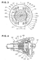
- the centrifugal clutch 23 has a clutch drum 31 provided on the blade driving shaft 24, a centrifugally pivotal member 32 (See FIG. 4) provided on the crankshaft 22 of the motor 21 and housed in the clutch drum 31, and a clutch case 34 connected to a motor housing 33, enclosing the pivotal member 32 and the clutch drum 31.
- the automatic braking mechanism 25 has a brake drum 35 integrally formed with and in the clutch case 34, centrifugal braking members 36 pivotally mounted to the clutch drum 31 such that they expand by a centrifugal force proportionate to the number of rotations of the clutch drum 31, and resilient members 37 (See FIG. 3) biasing the braking members 36 to the brake drum 35.
- the braking mechanism 25 is installed in the clutch case 34.
- Reference numeral 38 denotes a stopper.
- the motor 21 has a cylinder 41, a piston 42, a crankshaft 22, and an ignition plug 43.
- Reference numeral 44 denotes a fuel tank, 45 an oil tank, and 46 a starter.
- the clutch drum 31 has a tubular transmitting portion 47, a disc-shaped connecting portion 48 formed integrally with one end of the transmitting portion 47, and a connecting shaft 49 (See FIG. 4) mounted to the connecting portion 48.
- the two braking members 36, 36 are disposed around the brake drum 35 with a distance or interval L left therebetween, while the resilient members 37, 37 are extended between the adjacent braking members 36, 36.
- Serration 49a is formed centrally of the connecting shaft 49.
- Serration 24a is formed on the blade driving shaft 24.
- the serration 49a is in meshing engagement with the serration 24a.
- Each braking member 36 has an arc-shaped body 51.
- One end 52 of the body 51 is formed with a bearing 53 and a first hooking aperture 54.
- the other end 55 is formed with a second hooking aperture 56.
- An engaging portion 57 is formed in the middle, curved to the brake drum 35.
- a friction member 58 is attached to the engaging portion 57.
- Spindles 59 are attached to the connecting portion 48 of the clutch drum 31.
- the bearing 53 is mounted to the spindle 59.
- Reference numeral 61 denotes a retaining ring.
- the clutch case 34 includes a bearing support 62 provided on the inner surface of the brake drum 35, supporting the connecting shaft 49 via bearings 63, 63.
- the member 32 of the centrifugal clutch 23 swings when the number of rotations of the crankshaft 22 exceeds a predetermined value, abutting at one end 64 against the transmitting portion 47, thereby contacting the clutch drum 31.
- the automatic braking mechanism 25 of the bush cutting machine presses the braking drum 35 with the braking members 36, 36 as shown by arrows 1 ⁇ , 1 ⁇ . This is the state wherein the motor stops. For the cutting operation, the motor is started, increasing the number of its rotations.
- the two braking members 36, 36 are disposed around the brake drum 35 in an equidistantly spaced relation to each other and the resilient members 37, 37 are provided to extend between the adjacent braking members 36, 36, it becomes possible to evenly distribute the weight of the components around the rotational center, thereby preventing unbalanced rotation.
- the two braking members 36, 36 are provided around the brake drum 35 in an equally spaced relation to each other and the resilient members 37, 37 are provided to extend between the adjacent braking members 36, 36, it becomes possible to render the resulting machine compact and to achieve synchronization of the braking members 36, 36. This leads to reliable braking.
- the brake drum 35 is formed in the clutch case 34.
- the brake drum may be formed at any other fixed portion.
- braking members Although two braking members are provided around the brake drum 35, the number of such members may be greater.
- a bush cutting machine (10) including an automatic braking mechanism (25) having a brake drum (35) formed integrally with a clutch case (34) which houses a centrifugal clutch (23).
- an automatic braking mechanism (25) having a brake drum (35) formed integrally with a clutch case (34) which houses a centrifugal clutch (23).
- a clutch drum (31) When the number of rotations of a clutch drum (31) decreases, at least two braking members (36) press against the brake drum, whereby the clutch drum stops rotating, and a cutting blade (13) also stops rotating automatically.
Landscapes
- Engineering & Computer Science (AREA)
- General Engineering & Computer Science (AREA)
- Life Sciences & Earth Sciences (AREA)
- Environmental Sciences (AREA)
- Mechanical Engineering (AREA)
- Harvester Elements (AREA)
- Braking Arrangements (AREA)
- One-Way And Automatic Clutches, And Combinations Of Different Clutches (AREA)
Abstract
Description
Claims (2)
- A bush cutting machine (10) comprising:a motor (21);a centrifugal clutch (23) designed to establish drive connection when a number of rotations of an output shaft of said motor exceeds a predetermined value;a blade driving shaft (24) for transmitting a torque;a cutting blade (13) mounted to a distal end of said blade driving shaft;said centrifugal clutch comprising a clutch drum (31) provided on said blade driving shaft, a centrifugally pivotal member (32) provided on the output shaft of said motor and housed in said clutch drum, and a clutch case (34) connected to a motor housing (33) for enclosing said pivotal member and said clutch drum; andan automatic braking mechanism (25) housed in said clutch case and comprising a brake drum (35) formed integrally within said clutch case, at least two centrifugal braking members (36) pivotally mounted to said clutch drum in such a manner as to expand by a centrifugal force proportionate to the number of rotations of said clutch drum, and resilient members (37) for biasing said braking members to said brake drum, whereby said braking members are brought into abutting engagement with said brake drum with decrease in the number of rotations of said clutch drum.
- The bush cutting machine of claim 1, wherein said braking members (36) are disposed around said brake drum in equidistantly spaced relation to each other, and said resilient members (37) are provided to extend between adjacent two of said braking members.
Applications Claiming Priority (2)
| Application Number | Priority Date | Filing Date | Title |
|---|---|---|---|
| JP2000381407A JP2002176822A (en) | 2000-12-15 | 2000-12-15 | Brush cutter |
| JP2000381407 | 2000-12-15 |
Publications (3)
| Publication Number | Publication Date |
|---|---|
| EP1214872A2 true EP1214872A2 (en) | 2002-06-19 |
| EP1214872A3 EP1214872A3 (en) | 2002-07-03 |
| EP1214872B1 EP1214872B1 (en) | 2007-02-28 |
Family
ID=18849408
Family Applications (1)
| Application Number | Title | Priority Date | Filing Date |
|---|---|---|---|
| EP01129001A Expired - Lifetime EP1214872B1 (en) | 2000-12-15 | 2001-12-06 | Bush cutting machine |
Country Status (8)
| Country | Link |
|---|---|
| US (1) | US6578270B2 (en) |
| EP (1) | EP1214872B1 (en) |
| JP (1) | JP2002176822A (en) |
| KR (1) | KR100416183B1 (en) |
| CN (1) | CN1222397C (en) |
| CA (1) | CA2364352C (en) |
| DE (1) | DE60126898T2 (en) |
| TW (1) | TW553721B (en) |
Cited By (3)
| Publication number | Priority date | Publication date | Assignee | Title |
|---|---|---|---|---|
| FR2833509A1 (en) * | 2001-12-17 | 2003-06-20 | Stihl Maschf Andreas | MANUALLY GUIDED TOOL |
| US7041943B2 (en) | 2002-02-14 | 2006-05-09 | I G Bauerhin Gmbh | Electrical heating element for heating units of seats and steering wheels |
| EP1922912A1 (en) * | 2006-11-15 | 2008-05-21 | Husqvarna UK Limited | Brake assembly |
Families Citing this family (13)
| Publication number | Priority date | Publication date | Assignee | Title |
|---|---|---|---|---|
| JP3778422B2 (en) * | 2001-03-01 | 2006-05-24 | 本田技研工業株式会社 | Brush cutter |
| DE10160539B4 (en) | 2001-12-10 | 2017-06-08 | Andreas Stihl Ag & Co. | Two-stroke engine with flushing template and single-inlet carburetor |
| US6918451B2 (en) | 2002-04-11 | 2005-07-19 | Kioritz Corporation | Brake band and portable trimmer |
| JP2009121522A (en) * | 2007-11-12 | 2009-06-04 | F C C:Kk | Centrifugal clutch device |
| CN101467507B (en) * | 2007-12-27 | 2011-08-03 | 苏州宝时得电动工具有限公司 | Brake device of garden tools |
| DE102009043247A1 (en) * | 2009-09-28 | 2011-03-31 | Andreas Stihl Ag & Co. Kg | centrifugal clutch |
| CN103770158B (en) * | 2014-01-10 | 2016-05-11 | 浙江亚特电器有限公司 | A kind of brake structure of electric chain saw |
| DE102015106833A1 (en) * | 2015-04-30 | 2016-11-03 | Johnson Electric Germany GmbH & Co. KG | Centrifugal brake for Venetian blind drives |
| JP2018068155A (en) * | 2016-10-26 | 2018-05-10 | 株式会社やまびこ | Portable brush cutter |
| EP4326045A4 (en) | 2021-04-19 | 2025-05-21 | Milwaukee Electric Tool Corporation | TRIMMER HEAD |
| US12582029B2 (en) | 2021-06-30 | 2026-03-24 | Milwaukee Electric Tool Corporation | String trimmer head |
| DE212022000197U1 (en) | 2021-06-30 | 2024-02-19 | Milwaukee Electric Tool Corporation | String trimmer assembly and trimmer head for use with it |
| CN114451151B (en) * | 2021-12-27 | 2023-06-16 | 南京苏美达智能技术有限公司 | Emergency stop control system and control method for hybrid mower |
Family Cites Families (20)
| Publication number | Priority date | Publication date | Assignee | Title |
|---|---|---|---|---|
| US3760570A (en) * | 1972-09-05 | 1973-09-25 | Black & Decker Mfg Co | Centrifugally responsive brake for rotary tool |
| JPS5517655Y2 (en) * | 1973-11-27 | 1980-04-23 | ||
| JPS5238978Y2 (en) * | 1974-10-22 | 1977-09-03 | ||
| JPS5153248A (en) | 1974-11-05 | 1976-05-11 | Mitsubishi Electric Corp | IJODENATSUBOSHIKAIRO |
| US4006528A (en) * | 1974-11-22 | 1977-02-08 | Kaaz Machinery Co. Ltd. | Portable grass and brush cutter with brake and clutch |
| JPS571809B2 (en) | 1974-12-09 | 1982-01-13 | ||
| JPS532231A (en) * | 1976-06-26 | 1978-01-11 | Shikutani Kk | Brake arrangements for bush cleaner |
| US4279117A (en) * | 1980-01-30 | 1981-07-21 | The Murray Ohio Manufacturing Co. | Combined clutch and brake arrangement for a rotary lawnmower blade |
| JPS5940629U (en) * | 1982-09-08 | 1984-03-15 | 本田技研工業株式会社 | centrifugal clutch |
| JPS59186534U (en) * | 1983-05-31 | 1984-12-11 | 本田技研工業株式会社 | centrifugal clutch |
| FR2614377B3 (en) * | 1987-04-21 | 1989-07-21 | Peugeot Cycles | CLUTCH AND BRAKE DEVICE FOR DRIVING A ROTARY MEMBER SUCH AS A LAWNMOWER BLADE |
| JPH0216586Y2 (en) * | 1987-05-27 | 1990-05-08 | ||
| JPH0317077Y2 (en) * | 1988-02-09 | 1991-04-11 | ||
| JPH0317078Y2 (en) * | 1988-02-10 | 1991-04-11 | ||
| GB2277668A (en) * | 1993-04-23 | 1994-11-09 | Electrolux Northern | Clutch and brake assembly for a rotary mower |
| SE508924C2 (en) * | 1993-11-26 | 1998-11-16 | Electrolux Ab | Centrifugal coupling for a motor-driven work tool such as a chainsaw, hedge trimmer or the like |
| US5774993A (en) * | 1994-10-29 | 1998-07-07 | Andreas Stihl | Hand-held working tool, especially trimmer or edge cutter |
| JP3432406B2 (en) * | 1997-12-12 | 2003-08-04 | 株式会社共立 | Portable brush cutter |
| US6176016B1 (en) * | 1998-07-02 | 2001-01-23 | Honda Giken Kogyo Kabushiki Kaisha | Operation control lever unit for engine-powered working machine |
| JP4341804B2 (en) * | 2001-01-23 | 2009-10-14 | 本田技研工業株式会社 | Brush cutter |
-
2000
- 2000-12-15 JP JP2000381407A patent/JP2002176822A/en active Pending
-
2001
- 2001-12-03 CA CA002364352A patent/CA2364352C/en not_active Expired - Lifetime
- 2001-12-04 TW TW090130021A patent/TW553721B/en not_active IP Right Cessation
- 2001-12-06 DE DE60126898T patent/DE60126898T2/en not_active Expired - Lifetime
- 2001-12-06 EP EP01129001A patent/EP1214872B1/en not_active Expired - Lifetime
- 2001-12-12 US US10/015,406 patent/US6578270B2/en not_active Expired - Lifetime
- 2001-12-13 KR KR10-2001-0078764A patent/KR100416183B1/en not_active Expired - Fee Related
- 2001-12-14 CN CNB011438096A patent/CN1222397C/en not_active Expired - Fee Related
Cited By (5)
| Publication number | Priority date | Publication date | Assignee | Title |
|---|---|---|---|---|
| FR2833509A1 (en) * | 2001-12-17 | 2003-06-20 | Stihl Maschf Andreas | MANUALLY GUIDED TOOL |
| GB2385099A (en) * | 2001-12-17 | 2003-08-13 | Stihl Maschf Andreas | Manually operated tool with centrifugal clutch having a locating bearing |
| GB2385099B (en) * | 2001-12-17 | 2004-07-07 | Stihl Maschf Andreas | Manually operated tool |
| US7041943B2 (en) | 2002-02-14 | 2006-05-09 | I G Bauerhin Gmbh | Electrical heating element for heating units of seats and steering wheels |
| EP1922912A1 (en) * | 2006-11-15 | 2008-05-21 | Husqvarna UK Limited | Brake assembly |
Also Published As
| Publication number | Publication date |
|---|---|
| CN1358615A (en) | 2002-07-17 |
| DE60126898D1 (en) | 2007-04-12 |
| TW553721B (en) | 2003-09-21 |
| DE60126898T2 (en) | 2007-06-14 |
| EP1214872B1 (en) | 2007-02-28 |
| JP2002176822A (en) | 2002-06-25 |
| CA2364352A1 (en) | 2002-06-15 |
| US6578270B2 (en) | 2003-06-17 |
| KR100416183B1 (en) | 2004-01-24 |
| US20020078671A1 (en) | 2002-06-27 |
| CN1222397C (en) | 2005-10-12 |
| CA2364352C (en) | 2004-08-03 |
| KR20020046992A (en) | 2002-06-21 |
| EP1214872A3 (en) | 2002-07-03 |
Similar Documents
| Publication | Publication Date | Title |
|---|---|---|
| CA2364352C (en) | Bush cutting machine | |
| US4205737A (en) | Clutch-brake mechanism for rotary mower engines | |
| US4205509A (en) | Power transmission device for power-operated lawn mowing machine | |
| JP4341804B2 (en) | Brush cutter | |
| US5413200A (en) | Power assist system for vehicle | |
| CN106573319B (en) | hand guided work equipment | |
| FR2877697A1 (en) | PROTECTION CIRCUIT RELATING TO ROTATION SPEED, FOR CENTRIFUGAL CLUTCH | |
| JP3135557B2 (en) | A device for operating a brake device for stopping a power tool of a work machine | |
| JPH10313682A (en) | Braking device for power work equipment | |
| US8371421B2 (en) | Brake band holder | |
| US4728315A (en) | Two-speed drive with two belt pulleys and a centrifugal type friction-clutch coupling | |
| US4889215A (en) | Anti-overload centrifugal clutch | |
| US8973721B2 (en) | Braking apparatus | |
| US4667786A (en) | Blade-brake clutch device for lawn mower | |
| JPH0317078Y2 (en) | ||
| JP3992590B2 (en) | Clutch device with brake | |
| EP0080255B1 (en) | Engine control with self-energizing flywheel brake | |
| JPS585455Y2 (en) | combine | |
| JP2003184972A (en) | In-vehicle V-belt continuously variable transmission | |
| JPH056422Y2 (en) | ||
| KR0123539Y1 (en) | Car starting limiter | |
| JP3400152B2 (en) | Lawn mower drive | |
| JP2525651Y2 (en) | Chain saw | |
| KR870000085Y1 (en) | Carding machine flat drive | |
| JPH0724697Y2 (en) | Belt drive clutch / brake device |
Legal Events
| Date | Code | Title | Description |
|---|---|---|---|
| PUAI | Public reference made under article 153(3) epc to a published international application that has entered the european phase |
Free format text: ORIGINAL CODE: 0009012 |
|
| PUAL | Search report despatched |
Free format text: ORIGINAL CODE: 0009013 |
|
| AK | Designated contracting states |
Kind code of ref document: A2 Designated state(s): AT BE CH CY DE DK ES FI FR GB GR IE IT LI LU MC NL PT SE TR |
|
| AX | Request for extension of the european patent |
Free format text: AL;LT;LV;MK;RO;SI |
|
| AK | Designated contracting states |
Kind code of ref document: A3 Designated state(s): AT BE CH CY DE DK ES FI FR GB GR IE IT LI LU MC NL PT SE TR |
|
| AX | Request for extension of the european patent |
Free format text: AL;LT;LV;MK;RO;SI |
|
| RIC1 | Information provided on ipc code assigned before grant |
Free format text: 7A 01D 34/90 A, 7A 01D 34/00 B, 7A 01D 34/68 B, 7F 16D 67/02 B, 7F 16D 49/16 B |
|
| 17P | Request for examination filed |
Effective date: 20020808 |
|
| AKX | Designation fees paid |
Designated state(s): DE FR |
|
| GRAP | Despatch of communication of intention to grant a patent |
Free format text: ORIGINAL CODE: EPIDOSNIGR1 |
|
| GRAS | Grant fee paid |
Free format text: ORIGINAL CODE: EPIDOSNIGR3 |
|
| GRAA | (expected) grant |
Free format text: ORIGINAL CODE: 0009210 |
|
| AK | Designated contracting states |
Kind code of ref document: B1 Designated state(s): DE FR |
|
| REF | Corresponds to: |
Ref document number: 60126898 Country of ref document: DE Date of ref document: 20070412 Kind code of ref document: P |
|
| ET | Fr: translation filed | ||
| PLBE | No opposition filed within time limit |
Free format text: ORIGINAL CODE: 0009261 |
|
| STAA | Information on the status of an ep patent application or granted ep patent |
Free format text: STATUS: NO OPPOSITION FILED WITHIN TIME LIMIT |
|
| 26N | No opposition filed |
Effective date: 20071129 |
|
| REG | Reference to a national code |
Ref country code: FR Ref legal event code: PLFP Year of fee payment: 15 |
|
| REG | Reference to a national code |
Ref country code: FR Ref legal event code: PLFP Year of fee payment: 16 |
|
| REG | Reference to a national code |
Ref country code: FR Ref legal event code: PLFP Year of fee payment: 17 |
|
| PGFP | Annual fee paid to national office [announced via postgrant information from national office to epo] |
Ref country code: DE Payment date: 20191126 Year of fee payment: 19 |
|
| PGFP | Annual fee paid to national office [announced via postgrant information from national office to epo] |
Ref country code: FR Payment date: 20191115 Year of fee payment: 19 |
|
| REG | Reference to a national code |
Ref country code: DE Ref legal event code: R119 Ref document number: 60126898 Country of ref document: DE |
|
| PG25 | Lapsed in a contracting state [announced via postgrant information from national office to epo] |
Ref country code: FR Free format text: LAPSE BECAUSE OF NON-PAYMENT OF DUE FEES Effective date: 20201231 |
|
| PG25 | Lapsed in a contracting state [announced via postgrant information from national office to epo] |
Ref country code: DE Free format text: LAPSE BECAUSE OF NON-PAYMENT OF DUE FEES Effective date: 20210701 |