EP1214722B1 - Anordnung mit einem schaltgerät und einer auswerteeinrichtung zur ermittlung der restlebensdauer - Google Patents
Anordnung mit einem schaltgerät und einer auswerteeinrichtung zur ermittlung der restlebensdauer Download PDFInfo
- Publication number
- EP1214722B1 EP1214722B1 EP00960625A EP00960625A EP1214722B1 EP 1214722 B1 EP1214722 B1 EP 1214722B1 EP 00960625 A EP00960625 A EP 00960625A EP 00960625 A EP00960625 A EP 00960625A EP 1214722 B1 EP1214722 B1 EP 1214722B1
- Authority
- EP
- European Patent Office
- Prior art keywords
- contact piece
- switching device
- contact
- wear
- evaluation
- Prior art date
- Legal status (The legal status is an assumption and is not a legal conclusion. Google has not performed a legal analysis and makes no representation as to the accuracy of the status listed.)
- Expired - Lifetime
Links
- 238000011156 evaluation Methods 0.000 title claims abstract description 12
- 239000000919 ceramic Substances 0.000 claims description 2
- 238000002955 isolation Methods 0.000 claims description 2
- 238000001514 detection method Methods 0.000 description 8
- 230000003628 erosive effect Effects 0.000 description 4
- 230000006378 damage Effects 0.000 description 2
- 239000000969 carrier Substances 0.000 description 1
- 230000001419 dependent effect Effects 0.000 description 1
- 238000011161 development Methods 0.000 description 1
- 230000018109 developmental process Effects 0.000 description 1
- 239000000463 material Substances 0.000 description 1
- 238000012544 monitoring process Methods 0.000 description 1
- 230000003287 optical effect Effects 0.000 description 1
- 230000035699 permeability Effects 0.000 description 1
- 230000035945 sensitivity Effects 0.000 description 1
- 238000000926 separation method Methods 0.000 description 1
- 239000010409 thin film Substances 0.000 description 1
Images

Classifications
-
- G—PHYSICS
- G01—MEASURING; TESTING
- G01N—INVESTIGATING OR ANALYSING MATERIALS BY DETERMINING THEIR CHEMICAL OR PHYSICAL PROPERTIES
- G01N29/00—Investigating or analysing materials by the use of ultrasonic, sonic or infrasonic waves; Visualisation of the interior of objects by transmitting ultrasonic or sonic waves through the object
- G01N29/36—Detecting the response signal, e.g. electronic circuits specially adapted therefor
- G01N29/38—Detecting the response signal, e.g. electronic circuits specially adapted therefor by time filtering, e.g. using time gates
-
- G—PHYSICS
- G01—MEASURING; TESTING
- G01N—INVESTIGATING OR ANALYSING MATERIALS BY DETERMINING THEIR CHEMICAL OR PHYSICAL PROPERTIES
- G01N29/00—Investigating or analysing materials by the use of ultrasonic, sonic or infrasonic waves; Visualisation of the interior of objects by transmitting ultrasonic or sonic waves through the object
- G01N29/04—Analysing solids
- G01N29/11—Analysing solids by measuring attenuation of acoustic waves
-
- G—PHYSICS
- G01—MEASURING; TESTING
- G01N—INVESTIGATING OR ANALYSING MATERIALS BY DETERMINING THEIR CHEMICAL OR PHYSICAL PROPERTIES
- G01N29/00—Investigating or analysing materials by the use of ultrasonic, sonic or infrasonic waves; Visualisation of the interior of objects by transmitting ultrasonic or sonic waves through the object
- G01N29/34—Generating the ultrasonic, sonic or infrasonic waves, e.g. electronic circuits specially adapted therefor
- G01N29/348—Generating the ultrasonic, sonic or infrasonic waves, e.g. electronic circuits specially adapted therefor with frequency characteristics, e.g. single frequency signals, chirp signals
-
- G—PHYSICS
- G01—MEASURING; TESTING
- G01N—INVESTIGATING OR ANALYSING MATERIALS BY DETERMINING THEIR CHEMICAL OR PHYSICAL PROPERTIES
- G01N29/00—Investigating or analysing materials by the use of ultrasonic, sonic or infrasonic waves; Visualisation of the interior of objects by transmitting ultrasonic or sonic waves through the object
- G01N29/44—Processing the detected response signal, e.g. electronic circuits specially adapted therefor
- G01N29/46—Processing the detected response signal, e.g. electronic circuits specially adapted therefor by spectral analysis, e.g. Fourier analysis or wavelet analysis
-
- H—ELECTRICITY
- H01—ELECTRIC ELEMENTS
- H01H—ELECTRIC SWITCHES; RELAYS; SELECTORS; EMERGENCY PROTECTIVE DEVICES
- H01H1/00—Contacts
- H01H1/0015—Means for testing or for inspecting contacts, e.g. wear indicator
Definitions
- the invention relates to an arrangement with a switching device, in particular Low voltage switching device such as contactor, power, line or Motor protection switch or the like, according to the preamble of claim 1.
- a switching device in particular Low voltage switching device such as contactor, power, line or Motor protection switch or the like, according to the preamble of claim 1.
- the object of the invention is to create an arrangement that without pre-damage to the contact pieces and to any Time of wear of the contact piece, with an almost wear-free Condition detection a way to assess the Contact piece wear guaranteed.
- acoustic aids are found Use that on the one hand generate sound waves to a desired degree can, so that a defined impression of sound waves in the investigating contact piece is memorable and the other hand in Contact piece sound waves can detect.
- This High performance piezos can be in the form of Thin-film elements on the contact piece carrier, preferably immediately opposite the contact piece to be examined, on the other Side of the same contact piece carrier, may be arranged.
- Fig. 1 shows a switching device according to the invention in the form of a contactor.
- On such contactor comprises a multi-part housing 2 in the one Contact system (here three-pole), one acting on this contact system 4 Magnetic drive 6 and electronic and / or mechanical release elements are arranged.
- Positions AS1, AS2 and AS3 are indicated at which in the Switching device acoustic means 8 for sound generation and sound detection can be positioned.
- Preferred positions for attaching the acoustic means are the arrangement on the contact piece carrier 4c, in particular on the diametrically opposite contact piece 4d Side, or at the connection terminals of the switching device. hereby sound waves can be embossed directly into the contact piece 4d and the reflected structure-borne sound waves recorded and in an evaluation device be evaluated.
- FIG. 2 shows a contact system 4 with an associated magnetic drive 6 shown schematically.
- the contact system essentially exists from a movable switch contact 4a, here in the form of a three-pole trained contact bridge, which over the movable armature 6a Magnet drive 6 is driven and fixed switching contacts 4b.
- the switching device also has an evaluation unit, especially microprocessor, to determine the remaining life of the Switch contacts on.
- an evaluation unit especially microprocessor
- Reference values of different wear conditions are stored, which are then with the the actual values of the contact piece examined in each case are compared and depending on this, a certain degree of wear is determined and is assigned.
- Another possibility is to determine the Degrees of wear due to a program stored in the processor, wherein a wear value can be determined using a specific algorithm. The The determined degree of wear can then be queried via an interface (e.g. with PC or diagnostic device or the like) or by integrated Display means can be displayed at any time.
- Such a switching device with acoustic means 8 for Generation and detection of structure-borne noise signals are advantageously formed by piezo elements. It refers to Piezo elements over a wide radio frequency range, preferably 20 kHz to 225 kHz or even 500 kHz, deliver precise signals.
- both are in a single piezo element Structure-borne noise generating means and structure-borne noise detection means combined.
- Such an acoustic means 8 is preferably immediate arranged opposite on the contact piece carrier 4c.
- structure-borne sound waves are structure-borne sound waves in the Contact piece 4d stamped.
- the sound waves are reflected to different degrees and a certain one due to the detected reflected structure-borne sound waves Degree of wear determined. This is preferably done in the de-energized state of the Switching device, especially when the switch contacts are open. So be possible sources of interference eliminated from the outset.
- a separate configuration of generation and acquisition means is also possible. It is conceivable to arrange the generation and detection means also on the side of the contact piece carrier 4c opposite an associated contact piece 4d. In a further embodiment it is conceivable to assign cooperating generation and detection means to a pair of contacts and to arrange them on the outer sides of the respective contact piece carriers 4c. With this arrangement, the contact piece wear could only be determined with closed contacts, structure-borne sound waves being impressed to a defined extent on one side of the contact pair and structure-borne sound waves being recorded on the other side of the contact pair. The intensity of the structure-borne sound waves recorded is a measure of the wear of the contact pair.
- such an acoustic means 8 can directly on Contact carrier 4c of the associated contact piece 4d may be arranged.
- a a particularly preferred embodiment of the invention is one Means 8 associated switch contact mounted such that a galvanic Separation is guaranteed.
- a ceramic carrier 4e preferably between the Contact piece carrier 4c and the acoustic means 8 a ceramic carrier 4e assembled. This is a without negative impact on sound detection safe electrical isolation implemented.
- At least two means 8 are assigned to a contact piece 4d.
- This enables the partial, spatially resolved examination of a contact piece 4d. This is advantageous since contact pieces 4d are generally only subject to very uneven wear (erosion) and thus a qualitatively better determination of the condition of individual partial areas of the contact piece 4d is made possible.
- four means 8 are assigned to a contact piece 4d. These are in particular arranged such that each means 8 detects one of four coordinate fields, a Cartesian coordinate system depicted on the contact piece 4d.
- the various detection means (here piezos) assigned to a single contact piece 4d can be arranged in a ring-like manner. In this way, circular and / or annular partial areas of a contact piece 4d can be evaluated differentially.
- the individual means 8 or the individual partial areas of an means 8 can be weighted differently. For this purpose, means 8 with different sensitivity are provided in one possible embodiment, while identical or different means 8 are provided in another embodiment and the detected signals of the individual means 8 are weighted differently during the evaluation.
Landscapes
- Physics & Mathematics (AREA)
- General Health & Medical Sciences (AREA)
- Immunology (AREA)
- General Physics & Mathematics (AREA)
- Health & Medical Sciences (AREA)
- Life Sciences & Earth Sciences (AREA)
- Chemical & Material Sciences (AREA)
- Analytical Chemistry (AREA)
- Biochemistry (AREA)
- Pathology (AREA)
- Signal Processing (AREA)
- Engineering & Computer Science (AREA)
- Mathematical Physics (AREA)
- Spectroscopy & Molecular Physics (AREA)
- Acoustics & Sound (AREA)
- Testing Of Devices, Machine Parts, Or Other Structures Thereof (AREA)
- Investigating Or Analyzing Materials By The Use Of Ultrasonic Waves (AREA)
- Testing Electric Properties And Detecting Electric Faults (AREA)
- Indicating And Signalling Devices For Elevators (AREA)
- Motor Or Generator Frames (AREA)
- Measurement Of The Respiration, Hearing Ability, Form, And Blood Characteristics Of Living Organisms (AREA)
Description
- Figur 1:
- ein erfindungsgemäßes Schaltgerät in Form eines Schützes;
- Figur 2:
- die schematische Darstellung von Magnetantrieb und Kontaktsystem eines Schaltgerätes gemäß Fig. 1;
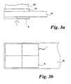
- Figur 3a:
- eine Seitenansicht eines Schaltkontaktes mit Piezoelement, und
- Figur 3b:
- der Schaltkontakt mit Piezoelement gemäß Fig. 3a aus Sicht in Pfeilrichtung.
In einer weiteren Ausführung ist vorstellbar, zusammenwirkende Erzeugungsund Erfassungsmittel einem Kontaktpaar zuzuordnen und auf den Außenseiten der jeweiligen Kontakstückträger 4c anzuordnen. Bei dieser Anordnung könnte eine Ermittlung des Kontaktstückverschleißes nur bei geschlossenen Kontakten erfolgen, wobei auf der einen Seite des Kontaktpaares in einem definierten Maß Körperschallwellen eingeprägt und auf der anderen Seite des Kontaktpaares Körperschallwellen erfaßt werden. Dabei stellt die Intensität der erfaßten Körperschallwellen ein Maß für den Verschleiß des Kontaktpaares dar.
Mit Vorteil werden einem Kontaktstück 4d vier Mittel 8 zugeordnet. Dabei sind diese insbesondere derart angeordnet, daß jedes Mittel 8 eines von vier Koordinatenfeldern, eines auf das Kontaktstück 4d abgebildeten kartesischen Koordinatensystems, erfaßt.
Zur Optimierung der Auswertung der erfaßten Körperschallwellen können die einzelnen Mittel 8, beziehungsweise die einzelnen Teilbereiche eines Mittels 8, unterschiedlich gewichtet werden. Hierfür sind in einer möglichen Ausführung unterschiedlich empfindliche Mittel 8 vorgesehen, während in einer anderen Ausführung identische oder unterschiedliche Mittel 8 vorgesehen sind und die erfaßten Signale der einzelnen Mittel 8 bei der Auswertung unterschiedlich gewichtet werden.
Claims (13)
- Anordnung miteinem Schaltgerät, insbesondere Niederspannungsschaltgerät, umfassend ein Gehäuse, ein darin angeordnetes Kontaktsystem (4) mit einem Kontaktstückträger (4c) und einem darauf angeordneten Kontaktstück (4d), Mittel (8) zur Erfassung eines Ersatzkriteriums für die Bestimmung der Restlebensdauer eines Kontaktstückes (4d), undeiner Auswerteeinrichtung zur Auswertung des Ersatzkriteriums, dadurch gekennzeichnet, daß die Mittel (8) zur Erzeugung und Erfassung von Körperschallwellen ausgebildet sind.
- Anordnung nach Anspruch 1, dadurch gekennzeichnet, daß die Mittel (8) durch ein Piezoelement, insbesondere ein Hochfrequenzpiezo für einen Frequenzbereich von 20 kHz bis 225 kHz, gebildet sind.
- Anordnung nach Anspruch 2, dadurch gekennzeichnet, daß Mittel (8) in einem gemeinsamen Piezoelement gebildet sind.
- Anordnung nach einem oder mehreren der Ansprüche 1-3, dadurch gekennzeichnet, daß die Mittel (8) auf dem Kontaktstückträger (4c), unmittelbar gegenüberliegend des Kontaktstückes (4d), angeordnet sind.
- Anordnung nach einem oder mehreren der Ansprüche 1-4, dadurch gekennzeichnet, daß einem Kontaktstück (4d) mindestens je zwei Mittel (8) zugeordnet sind, die ihrerseits wiederum unterschiedlichen Teilbereichen des Kontaktstückes (4d) zugeordnet sind.
- Anordnung nach einem oder mehreren der Ansprüche 1-4, dadurch gekennzeichnet, daß einem Kontaktstück (4d) genau je vier Mittel (8) zugeordnet sind.
- Anordnung nach Anspruch 6, dadurch gekennzeichnet, daß die Mittel (8) in Viertelsegmenten ausgebildet sind und über die gesamte geometrische Ausbreitung des Kontakstückes (4d) in vier einzelnen Koordinatenflächen die Ersatzkriterien für den Verschleiß des Kontaktstückes (4d) abbilden.
- Anordnung nach einem oder mehreren der Ansprüche 1-6, dadurch gekennzeichnet, daß die Mittel (8) kreisringförmig oder kreis- und kreisringförmig ausgebildet sind und über die gesamte geometrische Ausbreitung des Kontakstückes (4d) den Verschleiß des Kontaktstückes (4d) abbilden.
- Anordnung nach einem oder mehreren der Ansprüche 5-8, dadurch gekennzeichnet, daß einzelnen Mitteln (8) eine unterschiedliche Gewichtung zur Auswertung zukommt.
- Anordnung nach einem oder mehreren der Ansprüche 1-9, dadurch gekennzeichnet, daß die Mittel (8) derart an dem Kontaktstückträger (4c) angeordnet sind, das eine galvanische Trennung gewährleistet ist.
- Anordnung nach Anspruch 10, dadurch gekennzeichnet, daß die Mittel (8) auf einem Keramikträger (4e) angeordnet sind.
- Anordnung nach einem oder mehreren der Ansprüche 1-11, dadurch gekennzeichnet, daß die Auswerteeinrichtung in das Schaltgerät integriert ist.
- Anordnung nach einem oder mehreren der Ansprüche 1-12, dadurch gekennzeichnet, daß die Auswerteeinrichtung als separates mit dem Schaltgerät koppelbares Gerät ausgebildet ist.
Applications Claiming Priority (3)
| Application Number | Priority Date | Filing Date | Title |
|---|---|---|---|
| DE19945059 | 1999-09-20 | ||
| DE19945059A DE19945059A1 (de) | 1999-09-20 | 1999-09-20 | Anordnung mit einem Schaltgerät und einer Auswerteeinrichtung zur Ermittlung der Restlebensdauer |
| PCT/EP2000/008769 WO2001022452A1 (de) | 1999-09-20 | 2000-09-08 | Anordnung mit einem schaltgerät und einer auswerteeinrichtung zur ermittlung der restlebensdauer |
Publications (2)
| Publication Number | Publication Date |
|---|---|
| EP1214722A1 EP1214722A1 (de) | 2002-06-19 |
| EP1214722B1 true EP1214722B1 (de) | 2003-05-21 |
Family
ID=7922669
Family Applications (1)
| Application Number | Title | Priority Date | Filing Date |
|---|---|---|---|
| EP00960625A Expired - Lifetime EP1214722B1 (de) | 1999-09-20 | 2000-09-08 | Anordnung mit einem schaltgerät und einer auswerteeinrichtung zur ermittlung der restlebensdauer |
Country Status (6)
| Country | Link |
|---|---|
| US (1) | US6501355B2 (de) |
| EP (1) | EP1214722B1 (de) |
| AT (1) | ATE241208T1 (de) |
| DE (2) | DE19945059A1 (de) |
| ES (1) | ES2199176T3 (de) |
| WO (1) | WO2001022452A1 (de) |
Families Citing this family (1)
| Publication number | Priority date | Publication date | Assignee | Title |
|---|---|---|---|---|
| DE102020122065B4 (de) * | 2020-08-24 | 2022-12-01 | Te Connectivity Germany Gmbh | Kontaktanordnung mit einer Messvorrichtung zum Erfassen eines Kontaktierungszustands der Kontaktanordnung mittels eines akustischen Signals |
Family Cites Families (11)
| Publication number | Priority date | Publication date | Assignee | Title |
|---|---|---|---|---|
| JPS57151829A (en) * | 1981-03-13 | 1982-09-20 | Toshiba Corp | External diagnosis of switch device |
| JPS58156851A (ja) * | 1982-03-15 | 1983-09-17 | Toshiba Corp | 接点損傷診断装置 |
| DE3714802A1 (de) | 1987-05-04 | 1988-11-17 | Siemens Ag | Elektrischer schalter |
| US4975800A (en) * | 1988-03-14 | 1990-12-04 | Hitachi, Ltd. | Contact abnormality detecting system |
| JP2636097B2 (ja) * | 1991-08-08 | 1997-07-30 | 動力炉・核燃料開発事業団 | 浸漬型電動ポンプにおけるスラスト軸受の摩耗量の監視装置 |
| WO1993024845A1 (de) * | 1992-05-22 | 1993-12-09 | Siemens Aktiengesellschaft | Prüfverfahren zur qualitätskontrolle von elektromagnetisch betätigten schaltgeräten |
| DE4440423A1 (de) * | 1994-11-07 | 1996-05-09 | Siemens Ag | Verfahren und Einrichtung zum Überwachen einer Schaltstange |
| DE19523270C1 (de) * | 1995-06-27 | 1996-09-05 | Reinhausen Maschf Scheubeck | Verfahren zur Überwachung eines Stufenschalters |
| DE19640859B4 (de) * | 1996-10-03 | 2006-08-17 | Schmitt-Thomas, Karlheinz G., Prof. Dr.-Ing. | Verfahren und Vorrichtung zur zerstörungsfreien Feststellung des Werkstoffzustands in Bauteilen |
| DE19727986C2 (de) * | 1997-07-01 | 2001-10-11 | Moeller Gmbh | Schaltungsanordnung zur Ermittlung des Kontaktabbrandes von einem elektrischen Schaltgerät |
| DE19734224C1 (de) * | 1997-08-07 | 1999-02-04 | Siemens Ag | Verfahren und Vorrichtung zur Bestimmung von schaltgerätespezifischen Daten an Kontakten in Schaltgeräten und/oder zur Bestimmung von betriebsspezifischen Daten im damit geschalteten Netz |
-
1999
- 1999-09-20 DE DE19945059A patent/DE19945059A1/de not_active Withdrawn
-
2000
- 2000-09-08 ES ES00960625T patent/ES2199176T3/es not_active Expired - Lifetime
- 2000-09-08 DE DE50002286T patent/DE50002286D1/de not_active Expired - Fee Related
- 2000-09-08 WO PCT/EP2000/008769 patent/WO2001022452A1/de not_active Ceased
- 2000-09-08 AT AT00960625T patent/ATE241208T1/de not_active IP Right Cessation
- 2000-09-08 EP EP00960625A patent/EP1214722B1/de not_active Expired - Lifetime
-
2002
- 2002-03-20 US US10/101,786 patent/US6501355B2/en not_active Expired - Fee Related
Also Published As
| Publication number | Publication date |
|---|---|
| ES2199176T3 (es) | 2004-02-16 |
| WO2001022452A1 (de) | 2001-03-29 |
| EP1214722A1 (de) | 2002-06-19 |
| DE50002286D1 (de) | 2003-06-26 |
| US20020158728A1 (en) | 2002-10-31 |
| US6501355B2 (en) | 2002-12-31 |
| ATE241208T1 (de) | 2003-06-15 |
| DE19945059A1 (de) | 2001-03-22 |
Similar Documents
| Publication | Publication Date | Title |
|---|---|---|
| EP3861307B1 (de) | Verfahren zum bestimmen eines betriebszustands für ein elektrisches betriebsmittel mit einem schalterelement | |
| WO1999040408A1 (de) | Verfahren zur auswertung von kennwerten piezo-mechanischer systeme | |
| AT500968A4 (de) | Verfahren zur überwachung des betriebszustandes eines brennstoffzellenstapels | |
| EP0641446B1 (de) | Prüfverfahren zur qualitätskontrolle von elektromagnetisch betätigten schaltgeräten | |
| DE60301329T2 (de) | Elektromotor-überwachungssystem | |
| DE102012023146A1 (de) | Festsitz-messvorrichtung und festsitz-messverfahren | |
| EP1214723B1 (de) | Verfahren zur bestimmung der restlebensdauer der schaltkontakte in einem elektrischen schaltgerät und ein elektrisches schaltgerät mit einer auswerteeinrichtung zur durchführung des verfahrens | |
| WO2011012570A1 (de) | Anordnung und verfahren zum bestimmen eines ladezustands | |
| EP3994339B1 (de) | Drehschieber-aggregat sowie verfahren zur überwachung des verschleisses eines schiebers in einem solchen aggregat | |
| DE19945059A1 (de) | Anordnung mit einem Schaltgerät und einer Auswerteeinrichtung zur Ermittlung der Restlebensdauer | |
| DE29611558U1 (de) | Vorrichtung zur Erfassung von analogen Meßsignalen für die akustische Diagnose von Prüflingen | |
| DE102010043744A1 (de) | Schaltungsanordnung sowie Verfahren zur Überwachung des Schaltens einer Energiequelle zur Versorgung eines Elektroantriebs | |
| EP1098201A2 (de) | Zerstörungsfreie Prüfung von passiven Bauelementen | |
| EP0981759B1 (de) | Messanordnung zur elektrisch entkoppelten funktionsüberprüfung von im betrieb befindlichen systemen | |
| DE102011100305A1 (de) | Verfahren und Vorrichtung zur Bestimmung eines die Abnutzung eines Relais kennzeichnenden Parameters | |
| EP1752642B1 (de) | Verfahren und Vorrichtung zum Überwachen und Beurteilen der Funktion eines piezoelektrischen Aktors | |
| US6501356B2 (en) | Method for determining the remaining service life of the switch contacts in an electric switching device and electric switching device with an evaluation unit for carrying out said method | |
| DE102008003783A1 (de) | Vorrichtung und Verfahren zur Bestimmung des Schaltzustandes einer Bremse oder einer Kupplung | |
| DE4132533A1 (de) | Verfahren und zugehoerige messanordnung zur bewertung des lichtbogens an gleitkontakten von elektrischen maschinen | |
| DE102004052993A1 (de) | Vorrichtung zur Erkennung von Gehäusemanipulationen | |
| DE202012100919U1 (de) | Schallkopf zum Erzeugen und/oder Empfangen von Oberflächenschallwellen in einem Objekt und Werkzeug zum Ausrichten einer Wandleranordnung eines Schallkopfes | |
| EP0731552B1 (de) | Elektrische Maschine | |
| EP1403625A1 (de) | Kalibriergenerator mit Speicher ( Schwingungsmessung ) | |
| DE102008019674A1 (de) | Verfahren und Vorrichtung zum Prüfen mindestens eines einer Brennkraftmaschine zugeordneten Klopfsensors | |
| EP2427759B1 (de) | Verfahren zur prüfung eines hohlkörpers |
Legal Events
| Date | Code | Title | Description |
|---|---|---|---|
| PUAI | Public reference made under article 153(3) epc to a published international application that has entered the european phase |
Free format text: ORIGINAL CODE: 0009012 |
|
| 17P | Request for examination filed |
Effective date: 20020330 |
|
| AK | Designated contracting states |
Kind code of ref document: A1 Designated state(s): AT BE CH CY DE DK ES FI FR GB GR IE IT LI LU MC NL PT SE |
|
| AX | Request for extension of the european patent |
Free format text: AL;LT;LV;MK;RO;SI |
|
| GRAH | Despatch of communication of intention to grant a patent |
Free format text: ORIGINAL CODE: EPIDOS IGRA |
|
| GRAH | Despatch of communication of intention to grant a patent |
Free format text: ORIGINAL CODE: EPIDOS IGRA |
|
| GRAA | (expected) grant |
Free format text: ORIGINAL CODE: 0009210 |
|
| AK | Designated contracting states |
Designated state(s): AT BE CH CY DE DK ES FI FR GB GR IE IT LI LU MC NL PT SE |
|
| PG25 | Lapsed in a contracting state [announced via postgrant information from national office to epo] |
Ref country code: DK Free format text: LAPSE BECAUSE OF FAILURE TO SUBMIT A TRANSLATION OF THE DESCRIPTION OR TO PAY THE FEE WITHIN THE PRESCRIBED TIME-LIMIT Effective date: 20030521 Ref country code: FI Free format text: LAPSE BECAUSE OF FAILURE TO SUBMIT A TRANSLATION OF THE DESCRIPTION OR TO PAY THE FEE WITHIN THE PRESCRIBED TIME-LIMIT Effective date: 20030521 Ref country code: IE Free format text: LAPSE BECAUSE OF FAILURE TO SUBMIT A TRANSLATION OF THE DESCRIPTION OR TO PAY THE FEE WITHIN THE PRESCRIBED TIME-LIMIT Effective date: 20030521 Ref country code: NL Free format text: LAPSE BECAUSE OF FAILURE TO SUBMIT A TRANSLATION OF THE DESCRIPTION OR TO PAY THE FEE WITHIN THE PRESCRIBED TIME-LIMIT Effective date: 20030521 |
|
| REG | Reference to a national code |
Ref country code: GB Ref legal event code: FG4D Free format text: NOT ENGLISH |
|
| REG | Reference to a national code |
Ref country code: CH Ref legal event code: EP |
|
| REG | Reference to a national code |
Ref country code: IE Ref legal event code: FG4D Free format text: GERMAN |
|
| REF | Corresponds to: |
Ref document number: 50002286 Country of ref document: DE Date of ref document: 20030626 Kind code of ref document: P |
|
| REG | Reference to a national code |
Ref country code: CH Ref legal event code: NV Representative=s name: E. BLUM & CO. PATENTANWAELTE |
|
| PG25 | Lapsed in a contracting state [announced via postgrant information from national office to epo] |
Ref country code: PT Free format text: LAPSE BECAUSE OF FAILURE TO SUBMIT A TRANSLATION OF THE DESCRIPTION OR TO PAY THE FEE WITHIN THE PRESCRIBED TIME-LIMIT Effective date: 20030821 Ref country code: GR Free format text: LAPSE BECAUSE OF FAILURE TO SUBMIT A TRANSLATION OF THE DESCRIPTION OR TO PAY THE FEE WITHIN THE PRESCRIBED TIME-LIMIT Effective date: 20030821 |
|
| PG25 | Lapsed in a contracting state [announced via postgrant information from national office to epo] |
Ref country code: LU Free format text: LAPSE BECAUSE OF NON-PAYMENT OF DUE FEES Effective date: 20030908 Ref country code: CY Free format text: LAPSE BECAUSE OF FAILURE TO SUBMIT A TRANSLATION OF THE DESCRIPTION OR TO PAY THE FEE WITHIN THE PRESCRIBED TIME-LIMIT Effective date: 20030908 |
|
| REG | Reference to a national code |
Ref country code: SE Ref legal event code: TRGR |
|
| PG25 | Lapsed in a contracting state [announced via postgrant information from national office to epo] |
Ref country code: MC Free format text: LAPSE BECAUSE OF NON-PAYMENT OF DUE FEES Effective date: 20030930 Ref country code: BE Free format text: LAPSE BECAUSE OF NON-PAYMENT OF DUE FEES Effective date: 20030930 |
|
| GBT | Gb: translation of ep patent filed (gb section 77(6)(a)/1977) | ||
| LTIE | Lt: invalidation of european patent or patent extension |
Effective date: 20030521 |
|
| NLV1 | Nl: lapsed or annulled due to failure to fulfill the requirements of art. 29p and 29m of the patents act | ||
| REG | Reference to a national code |
Ref country code: IE Ref legal event code: FD4D Ref document number: 1214722E Country of ref document: IE |
|
| REG | Reference to a national code |
Ref country code: ES Ref legal event code: FG2A Ref document number: 2199176 Country of ref document: ES Kind code of ref document: T3 |
|
| ET | Fr: translation filed | ||
| PLBE | No opposition filed within time limit |
Free format text: ORIGINAL CODE: 0009261 |
|
| STAA | Information on the status of an ep patent application or granted ep patent |
Free format text: STATUS: NO OPPOSITION FILED WITHIN TIME LIMIT |
|
| BERE | Be: lapsed |
Owner name: *MOELLER G.M.B.H. Effective date: 20030930 |
|
| 26N | No opposition filed |
Effective date: 20040224 |
|
| PGFP | Annual fee paid to national office [announced via postgrant information from national office to epo] |
Ref country code: AT Payment date: 20060914 Year of fee payment: 7 Ref country code: CH Payment date: 20060914 Year of fee payment: 7 |
|
| PGFP | Annual fee paid to national office [announced via postgrant information from national office to epo] |
Ref country code: GB Payment date: 20060921 Year of fee payment: 7 |
|
| PGFP | Annual fee paid to national office [announced via postgrant information from national office to epo] |
Ref country code: FR Payment date: 20060922 Year of fee payment: 7 |
|
| PGFP | Annual fee paid to national office [announced via postgrant information from national office to epo] |
Ref country code: DE Payment date: 20060926 Year of fee payment: 7 |
|
| PGFP | Annual fee paid to national office [announced via postgrant information from national office to epo] |
Ref country code: ES Payment date: 20060928 Year of fee payment: 7 |
|
| PGFP | Annual fee paid to national office [announced via postgrant information from national office to epo] |
Ref country code: IT Payment date: 20060930 Year of fee payment: 7 |
|
| REG | Reference to a national code |
Ref country code: CH Ref legal event code: PFA Owner name: MOELLER GMBH Free format text: MOELLER GMBH#HEIN-MOELLER-STRASSE 7-11#53115 BONN (DE) -TRANSFER TO- MOELLER GMBH#HEIN-MOELLER-STRASSE 7-11#53115 BONN (DE) |
|
| PGFP | Annual fee paid to national office [announced via postgrant information from national office to epo] |
Ref country code: SE Payment date: 20060914 Year of fee payment: 7 |
|
| PG25 | Lapsed in a contracting state [announced via postgrant information from national office to epo] |
Ref country code: SE Free format text: LAPSE BECAUSE OF NON-PAYMENT OF DUE FEES Effective date: 20070909 |
|
| REG | Reference to a national code |
Ref country code: CH Ref legal event code: PL |
|
| EUG | Se: european patent has lapsed | ||
| GBPC | Gb: european patent ceased through non-payment of renewal fee |
Effective date: 20070908 |
|
| PG25 | Lapsed in a contracting state [announced via postgrant information from national office to epo] |
Ref country code: AT Free format text: LAPSE BECAUSE OF NON-PAYMENT OF DUE FEES Effective date: 20070908 |
|
| PG25 | Lapsed in a contracting state [announced via postgrant information from national office to epo] |
Ref country code: CH Free format text: LAPSE BECAUSE OF NON-PAYMENT OF DUE FEES Effective date: 20070930 Ref country code: DE Free format text: LAPSE BECAUSE OF NON-PAYMENT OF DUE FEES Effective date: 20080401 Ref country code: LI Free format text: LAPSE BECAUSE OF NON-PAYMENT OF DUE FEES Effective date: 20070930 |
|
| REG | Reference to a national code |
Ref country code: FR Ref legal event code: ST Effective date: 20080531 |
|
| PG25 | Lapsed in a contracting state [announced via postgrant information from national office to epo] |
Ref country code: FR Free format text: LAPSE BECAUSE OF NON-PAYMENT OF DUE FEES Effective date: 20071001 |
|
| PG25 | Lapsed in a contracting state [announced via postgrant information from national office to epo] |
Ref country code: GB Free format text: LAPSE BECAUSE OF NON-PAYMENT OF DUE FEES Effective date: 20070908 |
|
| REG | Reference to a national code |
Ref country code: ES Ref legal event code: FD2A Effective date: 20070910 |
|
| PG25 | Lapsed in a contracting state [announced via postgrant information from national office to epo] |
Ref country code: ES Free format text: LAPSE BECAUSE OF NON-PAYMENT OF DUE FEES Effective date: 20070910 |
|
| PG25 | Lapsed in a contracting state [announced via postgrant information from national office to epo] |
Ref country code: IT Free format text: LAPSE BECAUSE OF NON-PAYMENT OF DUE FEES Effective date: 20070908 |