EP1214663B1 - Scalable file server with highly available pairs - Google Patents
Scalable file server with highly available pairs Download PDFInfo
- Publication number
- EP1214663B1 EP1214663B1 EP00963270A EP00963270A EP1214663B1 EP 1214663 B1 EP1214663 B1 EP 1214663B1 EP 00963270 A EP00963270 A EP 00963270A EP 00963270 A EP00963270 A EP 00963270A EP 1214663 B1 EP1214663 B1 EP 1214663B1
- Authority
- EP
- European Patent Office
- Prior art keywords
- node
- file server
- pair
- nodes
- file
- Prior art date
- Legal status (The legal status is an assumption and is not a legal conclusion. Google has not performed a legal analysis and makes no representation as to the accuracy of the status listed.)
- Expired - Lifetime
Links
Images


Classifications
-
- G—PHYSICS
- G06—COMPUTING; CALCULATING OR COUNTING
- G06F—ELECTRIC DIGITAL DATA PROCESSING
- G06F11/00—Error detection; Error correction; Monitoring
- G06F11/07—Responding to the occurrence of a fault, e.g. fault tolerance
- G06F11/16—Error detection or correction of the data by redundancy in hardware
- G06F11/20—Error detection or correction of the data by redundancy in hardware using active fault-masking, e.g. by switching out faulty elements or by switching in spare elements
- G06F11/2053—Error detection or correction of the data by redundancy in hardware using active fault-masking, e.g. by switching out faulty elements or by switching in spare elements where persistent mass storage functionality or persistent mass storage control functionality is redundant
- G06F11/2089—Redundant storage control functionality
-
- G—PHYSICS
- G06—COMPUTING; CALCULATING OR COUNTING
- G06F—ELECTRIC DIGITAL DATA PROCESSING
- G06F11/00—Error detection; Error correction; Monitoring
- G06F11/07—Responding to the occurrence of a fault, e.g. fault tolerance
- G06F11/16—Error detection or correction of the data by redundancy in hardware
- G06F11/20—Error detection or correction of the data by redundancy in hardware using active fault-masking, e.g. by switching out faulty elements or by switching in spare elements
- G06F11/2002—Error detection or correction of the data by redundancy in hardware using active fault-masking, e.g. by switching out faulty elements or by switching in spare elements where interconnections or communication control functionality are redundant
-
- G—PHYSICS
- G06—COMPUTING; CALCULATING OR COUNTING
- G06F—ELECTRIC DIGITAL DATA PROCESSING
- G06F11/00—Error detection; Error correction; Monitoring
- G06F11/07—Responding to the occurrence of a fault, e.g. fault tolerance
- G06F11/16—Error detection or correction of the data by redundancy in hardware
- G06F11/20—Error detection or correction of the data by redundancy in hardware using active fault-masking, e.g. by switching out faulty elements or by switching in spare elements
- G06F11/2097—Error detection or correction of the data by redundancy in hardware using active fault-masking, e.g. by switching out faulty elements or by switching in spare elements maintaining the standby controller/processing unit updated
Definitions
- the invention relates to storage systems.
- U.S. Patent No. 5,688,943 (Attanasio et al.) (“the '943 patent” hereinafter) shows a system and method for recovering from failure in a disk access path of a clustered computing system.
- nodes communicate through an interconnection.
- the nodes include a processor, memory (possibly shared among nodes), and a number of disk adapters. Disks in the '943 patent can be shared by multiple nodes, providing for recovery from disk access failures.
- Computer storage systems are used to record and retrieve data.
- One way storage systems are characterized is by the amount of storage capacity they have.
- the capacity for storage systems has increased greatly over time.
- One problem in the known art is the difficulty of planning ahead for desired increases in storage capacity.
- a related problem in the known art is the difficulty in providing scalable storage at a relatively efficient cost. This has subjected customers to a dilemma; one can either purchase a file system with a single large file server, or purchase a file system with a number of smaller file servers.
- the single-server option has several drawbacks. (1) The customer must buy a larger file system than currently desired, so as to have room available for future expansion. (2) The entire file system can become unavailable if the file server fails for any reason. (3) The file system, although initially larger, is not easily scalable if the customer comes to desire a system that is larger than originally planned capacity.
- the multi-server option also has several drawbacks.
- the individual components of the multi-server device are tightly coordinated, (1) the same scalability problem occurs for the coordinating capacity for the individual components. That is, the customer must buy more coordinating' capacity than currently desired, so as to have room available for future expansion. (2) The individual components are themselves often obsolete by the time the planned-for greater capacity is actually needed. (3) Tightly coordinated systems are often very expensive relative to the amount of scalability desired.
- a method and system for performing a file server system that is scalable, that is, which can be increased in capacity without major system alterations, and which is relatively cost efficient with regard to that scalability.
- This advantage is achieved in an embodiment of the invention in which a plurality of file servers (each a pair of file server nodes) are interconnected. Each file server has a pair of controllers for simultaneously controlling a set of storage elements such as disk drives. File server commands are routed among file servers to the file servers having control of applicable storage elements, and in which each pair of file server nodes is reliable due to redundancy.
- the invention provides a file server system and a method for operating that system, which are defined in the appended claims and are easily scalable in number and type of individual components.
- a plurality of file servers (each including a pair of file server nodes) are coupled using inter-node connectivity, such as an inter-node network, so that any one pair can be accessed from any other pair.
- Each file server includes a pair of file server nodes, each of which has a memory and each of which conducts file server operations by simultaneously writing to its own memory and to that of its twin, the pair being used to simultaneously control a set of storage elements such as disk drives.
- File server commands or requests directed to particular mass storage elements are routed among file server nodes using an inter-node switch and processed by the file server nodes controlling those particular storage elements.
- Each file server (that is, each pair of file server nodes) is reliable due to its own redundancy.
- the mass storage elements are disposed and controlled to form a redundant array, such as a RAID (Redundant Array of Independent Disks) storage system.
- the inter-node network and inter-node switch are redundant, and file server commands or requests arriving at the network of pairs are coupled using the network and the switch to the appropriate pair and processed at that pair.
- each pair can be reached from each other pair, and no single point of failure prevents access to any individual storage element.
- the file servers are disposed and controlled to recognize failures of any single element in the file server system and to provide access to all mass storage elements despite any such failures.
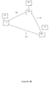
- Figure 1 shows a block diagram of a scalable and highly available file server system.
- a file server system 100 includes a set of file servers 110, each including a coupled pair of file server nodes 111 having co-coupled common sets of mass storage devices 112.
- Each node 111 is like the file server node further described in the Availability Disclosure.
- Each node 111 preferably includes its own memory and processor and is coupled to a common interconnect 120.
- Each node 111 is also coupled to a first network switch 130 and a second network switch 130.
- Each node 111 is coupled to the common interconnect 120, so as to be able to transmit information between any two file servers 110.
- the common interconnect 120 includes a set of communication links (not shown) which are redundant in the sense that even if any single communication link fails, each node 111 can still be contacted by each other node 111.
- the common interconnect 120 includes a NUMA (non-uniform memory access) interconnect, such as the SCI (Scalable Coherent Interconnect) interconnect operating at 1 gigabyte per second or the SCI-lite interconnect operating at 125 megabytes per second.
- NUMA non-uniform memory access
- Each file server 110 is coupled to the first network switch 130, so as to receive and respond to file server requests transmitted therefrom.
- there is also a second network switch 130 although the second network switch 130 is not required for operation of the file server system 100. Similar to the first network switch 130, each file server 110 is coupled to the second network switch 130, so as to receive and respond to file server requests transmitted therefrom.
- a sequence of file server requests arrives at the first network switch 130 or, if the second network switch 130 is present, at either the first network switch 130 or the second network switch 130.
- Either network switch 130 routes each file server request in its sequence to the particular file server 110 that is associated with the particular mass storage device needed for processing the file server request.
- One of the two nodes 111 at the designated file server 110 services the file server request and makes a file server response.
- the file server response is routed by one of the network switches 130 back to a source of the request.
- Figure 2A shows a block diagram of a first interconnect system for the file server system.
- the interconnect 120 includes a plurality of nodes 111, each of which is part of a file server 110.
- the nodes 111 are each disposed on a communication ring 211. Messages are transmitted between adjacent nodes 111 on each ring 211.
- each ring 211 comprises an SCI (Scalable Coherent Interconnect) network according to IEEE standard 1596-1992, or an SCI-lite network according to IEEE standard 1394.1. Both IEEE standard 1596-1992 and IEEE standard 1394.1 support remote memory access and DMA; the combination of these features is often called NUMA (non-uniform memory access).
- SCI networks operate at a data transmission rate of about 1 gigabyte per second; SCI-lite networks operate at a data transmission rate of about 125 megabytes per second.
- a communication switch 212 couples adjacent rings 211.
- the communication switch 212 receives and transmits messages on each ring 211, and operates to bridge messages from a first ring 211 to a second ring 211.
- the communication switch 212 bridges those messages that are transmitted on the first ring 211 and designated for transmission to the second ring 211.
- a switch 212 can also be coupled directly to a file server node 110.
- each ring 211 has a single node 111, so as to prevent any single point of failure (such as failure of the ring 211 or its switch 212) from preventing communication to more than one node 111.
- Figure 2B shows a block diagram of a second interconnect system for the file server system.
- the interconnect 120 includes a plurality of nodes 111, each of which is part of a file server 110.
- Each node 111 includes an associated network interface element 114.
- the network interface element 114 for each node 111 is like that described in the Availability Disclosure.
- the network interface elements 114 are coupled using a plurality of communication links 221, each of which couples two network interface elements 114 and communicates messages therebetween.
- the network interface elements 114 have sufficient communication links 221 to form a redundant communication network, so as to prevent any single point of failure (such as failure of any one network interface element 114) from preventing communication to more than one node 111.
- the network interface elements 114 are disposed with the communication links 221 to form a logical torus, in which each network interface element 114 is disposed on two logically orthogonal communication rings using the communication links 221.
- each of the logically orthogonal communication rings comprises an SCI network or an SCI-lite network, similar to the SCI network or SCI-lite network described with reference to figure 2A.
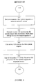
- Figure 3 shows a process flow diagram of operation of the file server system.
- a method 300 is performed by the components of the file server system 100, and includes a set of flow points and process steps as described herein.
- a device coupled to the file server system 100 desires to make a file system request.
- the device transmits a file system request to a selected network switch 130 coupled to the file server system 100.
- the network switch 130 receives the file system request.
- the network switch 130 determines which mass storage device the request applies to, and determines which file server 110 is coupled to that mass storage device.
- the network switch 130 transmits the request to that file server 110 (that is, to both of its nodes 111 in parallel), using the interconnect 120.
- the file server 110 receives the file system request.
- Each node 111 at the file server 110 queues the request for processing.
- one of the two nodes 111 at the file server 110 processes the file system request and responds thereto.
- the other one of the two nodes 111 at the file server 110 discards the request without further processing.
- the file server system 100 is still able to process the request and respond to the requesting device.
Landscapes
- Engineering & Computer Science (AREA)
- Theoretical Computer Science (AREA)
- Quality & Reliability (AREA)
- Physics & Mathematics (AREA)
- General Engineering & Computer Science (AREA)
- General Physics & Mathematics (AREA)
- Information Retrieval, Db Structures And Fs Structures Therefor (AREA)
- Hardware Redundancy (AREA)
- Multi Processors (AREA)
Abstract
Description
- The invention relates to storage systems.
- U.S. Patent No. 5,688,943 (Attanasio et al.) ("the '943 patent" hereinafter) shows a system and method for recovering from failure in a disk access path of a clustered computing system. In the '943 patent, nodes communicate through an interconnection. The nodes include a processor, memory (possibly shared among nodes), and a number of disk adapters. Disks in the '943 patent can be shared by multiple nodes, providing for recovery from disk access failures.
- In an article by the inventor, Steven R. Kleiman, and others, entitled "Using NUMA Interconnections for Highly Available Filers," two independent file server appliances are connected via a nonuniform-memory-access network. This system provides some survivability to hardware faults with minimal disruption to clients.
- More generally, computer storage systems are used to record and retrieve data. One way storage systems are characterized is by the amount of storage capacity they have. The capacity for storage systems has increased greatly over time. One problem in the known art is the difficulty of planning ahead for desired increases in storage capacity. A related problem in the known art is the difficulty in providing scalable storage at a relatively efficient cost. This has subjected customers to a dilemma; one can either purchase a file system with a single large file server, or purchase a file system with a number of smaller file servers.
- The single-server option has several drawbacks. (1) The customer must buy a larger file system than currently desired, so as to have room available for future expansion. (2) The entire file system can become unavailable if the file server fails for any reason. (3) The file system, although initially larger, is not easily scalable if the customer comes to desire a system that is larger than originally planned capacity.
- The multi-server option also has several drawbacks. In systems in which the individual components of the multi-server device are tightly coordinated, (1) the same scalability problem occurs for the coordinating capacity for the individual components. That is, the customer must buy more coordinating' capacity than currently desired, so as to have room available for future expansion. (2) The individual components are themselves often obsolete by the time the planned-for greater capacity is actually needed. (3) Tightly coordinated systems are often very expensive relative to the amount of scalability desired.
- In systems in which the individual components of the multi-server device are only loosely coordinated, it is difficult to cause the individual components to behave in a coordinated manner so as to emulate a single file server. Although failure of a single file server does not cause the entire file system to become unavailable, it does cause any files stored on that particular file server to become unavailable. If those files were critical to operation of the system, or some subsystem thereof, the applicable system or subsystem will be unavailable as a result. Administrative difficulties generally increase to due to a larger number of smaller file servers.
- Accordingly, it would be advantageous to provide a method and system for performing a file server system that is scalable, that is, which can be increased in capacity without major system alterations, and which is relatively cost efficient with regard to that scalability. This advantage is achieved in an embodiment of the invention in which a plurality of file servers (each a pair of file server nodes) are interconnected. Each file server has a pair of controllers for simultaneously controlling a set of storage elements such as disk drives. File server commands are routed among file servers to the file servers having control of applicable storage elements, and in which each pair of file server nodes is reliable due to redundancy.
- It would also be advantageous to provide a storage system that is resistant to failures of individual system elements, and that can continue to operate after any single point of failure. This advantage is achieved in an embodiment of the invention like that described in "Highly Available File Servers," WO 99/46680 (Network Appliance, Inc.), published on 16 September 1999.
- The invention provides a file server system and a method for operating that system, which are defined in the appended claims and are easily scalable in number and type of individual components. A plurality of file servers (each including a pair of file server nodes) are coupled using inter-node connectivity, such as an inter-node network, so that any one pair can be accessed from any other pair. Each file server includes a pair of file server nodes, each of which has a memory and each of which conducts file server operations by simultaneously writing to its own memory and to that of its twin, the pair being used to simultaneously control a set of storage elements such as disk drives. File server commands or requests directed to particular mass storage elements are routed among file server nodes using an inter-node switch and processed by the file server nodes controlling those particular storage elements. Each file server (that is, each pair of file server nodes) is reliable due to its own redundancy.
- In a preferred embodiment, the mass storage elements are disposed and controlled to form a redundant array, such as a RAID (Redundant Array of Independent Disks) storage system. The inter-node network and inter-node switch are redundant, and file server commands or requests arriving at the network of pairs are coupled using the network and the switch to the appropriate pair and processed at that pair. Thus, each pair can be reached from each other pair, and no single point of failure prevents access to any individual storage element. The file servers are disposed and controlled to recognize failures of any single element in the file server system and to provide access to all mass storage elements despite any such failures.
-
- Figure 1 shows a block diagram of a scalable and highly available file server system.
- Figure 2A shows a block diagram of a first interconnect system for the file server system.
- Figure 2B shows a block diagram of a second interconnect system for the file server system.
- Figure 3 shows a process flow diagram of operation of the file server system.
- In the following description, a preferred embodiment of the invention is described with regard to preferred process steps and data structures. However, those skilled in the art would recognize, after perusal of this application, that embodiments of the invention may be implemented using one or more general purpose processors (or special purpose processors adapted to the particular process steps and data structures) operating under program control, and that implementation of the preferred process steps and data structures described herein using such equipment would not require undue experimentation or further invention.
- Inventions described herein can be used in conjunction with inventions described in "Highly Available File Servers," WO 99/46680 (Network Appliance, Inc.), published on 16 September 1999. This application is herein referred to as the "Availability Disclosure."
- Figure 1 shows a block diagram of a scalable and highly available file server system.
- A
file server system 100 includes a set offile servers 110, each including a coupled pair offile server nodes 111 having co-coupled common sets ofmass storage devices 112. Eachnode 111 is like the file server node further described in the Availability Disclosure. Eachnode 111 preferably includes its own memory and processor and is coupled to acommon interconnect 120. Eachnode 111 is also coupled to afirst network switch 130 and asecond network switch 130. - Each
node 111 is coupled to thecommon interconnect 120, so as to be able to transmit information between any twofile servers 110. Thecommon interconnect 120 includes a set of communication links (not shown) which are redundant in the sense that even if any single communication link fails, eachnode 111 can still be contacted by eachother node 111. - In a preferred embodiment, the
common interconnect 120 includes a NUMA (non-uniform memory access) interconnect, such as the SCI (Scalable Coherent Interconnect) interconnect operating at 1 gigabyte per second or the SCI-lite interconnect operating at 125 megabytes per second. - Each
file server 110 is coupled to thefirst network switch 130, so as to receive and respond to file server requests transmitted therefrom. In a preferred embodiment there is also asecond network switch 130, although thesecond network switch 130 is not required for operation of thefile server system 100. Similar to thefirst network switch 130, eachfile server 110 is coupled to thesecond network switch 130, so as to receive and respond to file server requests transmitted therefrom. - In operation of the
file server system 100, as further described herein, a sequence of file server requests arrives at thefirst network switch 130 or, if thesecond network switch 130 is present, at either thefirst network switch 130 or thesecond network switch 130. Either network switch 130 routes each file server request in its sequence to theparticular file server 110 that is associated with the particular mass storage device needed for processing the file server request. - One of the two
nodes 111 at the designatedfile server 110 services the file server request and makes a file server response. The file server response is routed by one of the network switches 130 back to a source of the request. - Figure 2A shows a block diagram of a first interconnect system for the file server system.
- In a first preferred embodiment, the
interconnect 120 includes a plurality ofnodes 111, each of which is part of afile server 110. Thenodes 111 are each disposed on acommunication ring 211. Messages are transmitted betweenadjacent nodes 111 on eachring 211. - In this first preferred embodiment, each
ring 211 comprises an SCI (Scalable Coherent Interconnect) network according to IEEE standard 1596-1992, or an SCI-lite network according to IEEE standard 1394.1. Both IEEE standard 1596-1992 and IEEE standard 1394.1 support remote memory access and DMA; the combination of these features is often called NUMA (non-uniform memory access). SCI networks operate at a data transmission rate of about 1 gigabyte per second; SCI-lite networks operate at a data transmission rate of about 125 megabytes per second. - A
communication switch 212 couplesadjacent rings 211. Thecommunication switch 212 receives and transmits messages on eachring 211, and operates to bridge messages from afirst ring 211 to asecond ring 211. Thecommunication switch 212 bridges those messages that are transmitted on thefirst ring 211 and designated for transmission to thesecond ring 211. Aswitch 212 can also be coupled directly to afile server node 110. - In this first preferred embodiment, each
ring 211 has asingle node 111, so as to prevent any single point of failure (such as failure of thering 211 or its switch 212) from preventing communication to more than onenode 111. - Figure 2B shows a block diagram of a second interconnect system for the file server system.
- In a second preferred embodiment, the
interconnect 120 includes a plurality ofnodes 111, each of which is part of afile server 110. Eachnode 111 includes an associatednetwork interface element 114. In a preferred embodiment, thenetwork interface element 114 for eachnode 111 is like that described in the Availability Disclosure. - The
network interface elements 114 are coupled using a plurality ofcommunication links 221, each of which couples twonetwork interface elements 114 and communicates messages therebetween. - The
network interface elements 114 havesufficient communication links 221 to form a redundant communication network, so as to prevent any single point of failure (such as failure of any one network interface element 114) from preventing communication to more than onenode 111. - In this second preferred embodiment, the
network interface elements 114 are disposed with thecommunication links 221 to form a logical torus, in which eachnetwork interface element 114 is disposed on two logically orthogonal communication rings using the communication links 221. - In this second preferred embodiment, each of the logically orthogonal communication rings comprises an SCI network or an SCI-lite network, similar to the SCI network or SCI-lite network described with reference to figure 2A.
- Figure 3 shows a process flow diagram of operation of the file server system.
- A
method 300 is performed by the components of thefile server system 100, and includes a set of flow points and process steps as described herein. - At a
flow point 310, a device coupled to thefile server system 100 desires to make a file system request. - At a
step 311, the device transmits a file system request to a selectednetwork switch 130 coupled to thefile server system 100. - At a
step 312, thenetwork switch 130 receives the file system request. Thenetwork switch 130 determines which mass storage device the request applies to, and determines whichfile server 110 is coupled to that mass storage device. Thenetwork switch 130 transmits the request to that file server 110 (that is, to both of itsnodes 111 in parallel), using theinterconnect 120. - At a
step 313, thefile server 110 receives the file system request. Eachnode 111 at thefile server 110 queues the request for processing. - At a
step 314, one of the twonodes 111 at thefile server 110 processes the file system request and responds thereto. The other one of the twonodes 111 at thefile server 110 discards the request without further processing. - At a
flow point 320, the file system request has been successfully processed. - If any single point of failure occurs between the requesting device and the mass storage device to which the file system request applies, the
file server system 100 is still able to process the request and respond to the requesting device. - If either one of the network switches 130 fails, the
other network switch 130 is able to receive the file system request and transmit it to theappropriate file server 110. - If any link in the
interconnect 120 fails, the remaining links in theinterconnect 120 are able to transmit the message to theappropriate file server 110. - If either
node 111 at thefile server 110 fails, theother node 111 is able to process the file system request using the appropriate mass storage device. Becausenodes 111 at eachfile server 110 are coupled in pairs, eachfile server 110 is highly available. Becausefile servers 110 are coupled together for managing collections of mass storage devices, theentire system 100 is scalable by addition offile servers 110. Thus, each cluster offile servers 110 is scalable by addition offile servers 110. - If any one of the mass storage devices (other than the actual target of the file system request) fails, there is no effect on the ability of the other mass storage devices to respond to processing of the request, and there is no effect on either of the two
nodes 111 which process requests for that mass storage device. - Although preferred embodiments are disclosed herein, many variations are possible which remain within the scope, of the invention, and these variations would become clear to those skilled in the art after perusal of this application.
Claims (22)
- A file server system including
a plurality of file server nodes (111);
at least one inter-node connectivity element (120) coupled to said plurality of nodes;
at least one switch (13) coupled to said plurality of nodes and disposed for coupling file server commands to ones thereof;
characterized in that at least some of said nodes (111) are arranged in pairs in file servers, and in each of said file servers, both nodes are coupled to each storage element in a set of storage elements (112) for the file server (110), and both nodes (111) include at least a processor and a memory so as to be disposed to control said storage elements (112) in response to said file server commands, with said file server commands directed toward one of said file servers and then serviced by a designated one of said file server nodes in said one of said file servers. - A system as in claim 1, wherein at least some of said pairs are disposed for failover from a first node to a second node.
- A system as in claim 1, wherein
each said storage element corresponds to one said pair;
each said storage element is coupled to both nodes in said corresponding pair;
whereby both nodes in said corresponding pair are equally capable of controlling said storage element. - A system as in claim 1, wherein said connectivity element includes a NUMA network.
- A system as in claim 1, wherein said file server system is scalable by addition of a server comprising a set of pairs of said nodes.
- A systein as in claim 1, wherein said set of storage elements coupled to at least one said pair includes a RAID storage system.
- A system as in claim 1, wherein
each pair includes a first node and a second node;
each pair is disposed to receive file server commands directed to either said first node or to said second node;
each pair is disposed when said file server commands are directed to said first node to execute said file server commands at said first node and to store a copy of said file server commands at said second node; and
each pair is disposed when said file server commands are directed to said second node to execute said file server commands at said second node and to store a copy of said file server commands at said first node. - A system as in claim 7, wherein
each said pair is disposed when said file server commands are directed to said first node and said first node is inoperable to execute said file server commands at said second node; and
each pair is disposed when said file server commands are directed to said second node and said second node is inoperable to execute said file server commands at said first node. - A system as in claim 1, wherein
each pair is disposed to receive a file server command;
each pair is disposed so that a first node responds to said file server command while a second node records said file server command; and
each pair is disposed to failover from said first node to said second node. - A system as in claim 9, wherein
each pair is disposed to receive a second file server command;
each pair is disposed so that said second node responds to said second file server command while said first node records said file server command; and
each pair is disposed to failover from said first node to said second node. - A system as in claim 9, wherein said first node controls said storage elements in response to said file server command while said second node is coupled to said storage elements and does not control said storage elements in response to said file server command.
- A method of operating a file server system, said method including steps for
operating a plurality of file server nodes (111) in sets of pairs, each said pair included in a file server (110), both nodes for each file server (110) being coupled to each storage element in a set of storage elements (112) for the file server (110), and both nodes (111) for each file server (110) including at least a processor and a memory so as to be disposed to control said storage elements (112) in response to a set of file server commands, with said file server commands directed toward one of said file servers and then serviced by a designated one of said file server nodes in said one of said file servers;
coupling said file server commands to said pairs of nodes (110, 111);
coupling a set of messages between ones of said nodes (111) in a first of said pairs and ones of said nodes (111) in a second of said pairs. - A method as in claim 12, including steps for failover from a first node to a second node, and from said second node to said first node, in each said pair.
- A method as in claim 12, including steps for scaling said file server by addition of a set of pairs of said nodes.
- A method as in claim 12, including steps for controlling a set of storage elements corresponding to one said pair from either node in said pair.
- A method as in claim 15, including steps for operating said set of storage elements according to a RAID storage method.
- A method as in claim 12, including steps for
receiving file server commands directed to either a first node or to a second node in each said pair;
when said file server commands are directed to said first node, responding to said file server commands at said first node and storing a copy of said file server commands at said second node; and
when said file server commands are directed to said second node, responding to said file server commands at said second node and storing a copy of said file server commands at said first node. - A method as in claim 17, including steps for
when said file server commands are directed to said first node and said first node is inoperable, responding to said file server commands at said second node using said copy at said second node; and
when said file server commands are directed to said second node and said second node is inoperable, responding to said file server commands at said first node using said copy at said first node. - A method as in claim 12, including steps for
receiving a file server command at one said pair;
responding to said file server command at a first node while recording said file server command at a second node; and
failing over from said first node to said second node. - A method as in claim 19, including steps for
receiving a second file server command at said one pair;
responding to said file server command at said second node while recording said file server command at said first node; and
failing over from said first node to said second node. - A method as in claim 19, including steps for controlling said storage elements in response to said file server command by said first node while said second node is coupled to said storage elements and does not control said storage elements in response to said file server command.
- A computer program comprising program code means that, when executed on a computer system, cause the computer system to effect the steps of any one of claims 12 to 21.
Applications Claiming Priority (5)
| Application Number | Priority Date | Filing Date | Title |
|---|---|---|---|
| US383340 | 1982-05-27 | ||
| US15045399P | 1999-08-24 | 1999-08-24 | |
| US150453P | 1999-08-24 | ||
| US09/383,340 US6961749B1 (en) | 1999-08-25 | 1999-08-25 | Scalable file server with highly available pairs |
| PCT/US2000/023349 WO2001014991A2 (en) | 1999-08-24 | 2000-08-24 | Scalable file server with highly available pairs |
Publications (2)
| Publication Number | Publication Date |
|---|---|
| EP1214663A2 EP1214663A2 (en) | 2002-06-19 |
| EP1214663B1 true EP1214663B1 (en) | 2006-06-14 |
Family
ID=26847678
Family Applications (1)
| Application Number | Title | Priority Date | Filing Date |
|---|---|---|---|
| EP00963270A Expired - Lifetime EP1214663B1 (en) | 1999-08-24 | 2000-08-24 | Scalable file server with highly available pairs |
Country Status (6)
| Country | Link |
|---|---|
| EP (1) | EP1214663B1 (en) |
| JP (1) | JP2003507818A (en) |
| AU (1) | AU7470700A (en) |
| DE (1) | DE60028793T2 (en) |
| HK (1) | HK1045575B (en) |
| WO (1) | WO2001014991A2 (en) |
Cited By (10)
| Publication number | Priority date | Publication date | Assignee | Title |
|---|---|---|---|---|
| US11281484B2 (en) | 2016-12-06 | 2022-03-22 | Nutanix, Inc. | Virtualized server systems and methods including scaling of file system virtual machines |
| US11537384B2 (en) | 2016-02-12 | 2022-12-27 | Nutanix, Inc. | Virtualized file server distribution across clusters |
| US11562034B2 (en) | 2016-12-02 | 2023-01-24 | Nutanix, Inc. | Transparent referrals for distributed file servers |
| US11568073B2 (en) | 2016-12-02 | 2023-01-31 | Nutanix, Inc. | Handling permissions for virtualized file servers |
| US11675746B2 (en) | 2018-04-30 | 2023-06-13 | Nutanix, Inc. | Virtualized server systems and methods including domain joining techniques |
| US11770447B2 (en) | 2018-10-31 | 2023-09-26 | Nutanix, Inc. | Managing high-availability file servers |
| US11775397B2 (en) | 2016-12-05 | 2023-10-03 | Nutanix, Inc. | Disaster recovery for distributed file servers, including metadata fixers |
| US11888599B2 (en) | 2016-05-20 | 2024-01-30 | Nutanix, Inc. | Scalable leadership election in a multi-processing computing environment |
| US11954078B2 (en) | 2016-12-06 | 2024-04-09 | Nutanix, Inc. | Cloning virtualized file servers |
| US12072770B2 (en) | 2021-08-19 | 2024-08-27 | Nutanix, Inc. | Share-based file server replication for disaster recovery |
Families Citing this family (12)
| Publication number | Priority date | Publication date | Assignee | Title |
|---|---|---|---|---|
| US6119244A (en) | 1998-08-25 | 2000-09-12 | Network Appliance, Inc. | Coordinating persistent status information with multiple file servers |
| US6961749B1 (en) | 1999-08-25 | 2005-11-01 | Network Appliance, Inc. | Scalable file server with highly available pairs |
| US7308512B1 (en) | 2001-05-16 | 2007-12-11 | Network Appliance, Inc. | Fiber channel adaptor for serial or parallel ATA disks |
| US7146524B2 (en) | 2001-08-03 | 2006-12-05 | Isilon Systems, Inc. | Systems and methods for providing a distributed file system incorporating a virtual hot spare |
| US20030217211A1 (en) | 2002-05-14 | 2003-11-20 | Rust Robert A. | Controller communications over an always-on controller interconnect |
| US6857001B2 (en) | 2002-06-07 | 2005-02-15 | Network Appliance, Inc. | Multiple concurrent active file systems |
| US7024586B2 (en) | 2002-06-24 | 2006-04-04 | Network Appliance, Inc. | Using file system information in raid data reconstruction and migration |
| EP2284735A1 (en) | 2002-11-14 | 2011-02-16 | Isilon Systems, Inc. | Systems and methods for restriping files in a distributed file system |
| US7346720B2 (en) | 2005-10-21 | 2008-03-18 | Isilon Systems, Inc. | Systems and methods for managing concurrent access requests to a shared resource |
| US8966080B2 (en) | 2007-04-13 | 2015-02-24 | Emc Corporation | Systems and methods of managing resource utilization on a threaded computer system |
| US10585769B2 (en) | 2017-09-05 | 2020-03-10 | International Business Machines Corporation | Method for the implementation of a high performance, high resiliency and high availability dual controller storage system |
| US11768809B2 (en) * | 2020-05-08 | 2023-09-26 | Nutanix, Inc. | Managing incremental snapshots for fast leader node bring-up |
Family Cites Families (2)
| Publication number | Priority date | Publication date | Assignee | Title |
|---|---|---|---|---|
| DE69521101T2 (en) * | 1994-10-31 | 2001-10-18 | International Business Machines Corp., Armonk | Shared virtual disks with application-transparent recovery |
| US5862312A (en) * | 1995-10-24 | 1999-01-19 | Seachange Technology, Inc. | Loosely coupled mass storage computer cluster |
-
2000
- 2000-08-24 DE DE60028793T patent/DE60028793T2/en not_active Expired - Lifetime
- 2000-08-24 JP JP2001519283A patent/JP2003507818A/en active Pending
- 2000-08-24 WO PCT/US2000/023349 patent/WO2001014991A2/en active IP Right Grant
- 2000-08-24 AU AU74707/00A patent/AU7470700A/en not_active Abandoned
- 2000-08-24 EP EP00963270A patent/EP1214663B1/en not_active Expired - Lifetime
-
2002
- 2002-09-20 HK HK02106857.7A patent/HK1045575B/en not_active IP Right Cessation
Cited By (23)
| Publication number | Priority date | Publication date | Assignee | Title |
|---|---|---|---|---|
| US11669320B2 (en) | 2016-02-12 | 2023-06-06 | Nutanix, Inc. | Self-healing virtualized file server |
| US11966730B2 (en) | 2016-02-12 | 2024-04-23 | Nutanix, Inc. | Virtualized file server smart data ingestion |
| US12014166B2 (en) | 2016-02-12 | 2024-06-18 | Nutanix, Inc. | Virtualized file server user views |
| US11550558B2 (en) | 2016-02-12 | 2023-01-10 | Nutanix, Inc. | Virtualized file server deployment |
| US11550559B2 (en) | 2016-02-12 | 2023-01-10 | Nutanix, Inc. | Virtualized file server rolling upgrade |
| US11550557B2 (en) | 2016-02-12 | 2023-01-10 | Nutanix, Inc. | Virtualized file server |
| US11537384B2 (en) | 2016-02-12 | 2022-12-27 | Nutanix, Inc. | Virtualized file server distribution across clusters |
| US11922157B2 (en) | 2016-02-12 | 2024-03-05 | Nutanix, Inc. | Virtualized file server |
| US11579861B2 (en) | 2016-02-12 | 2023-02-14 | Nutanix, Inc. | Virtualized file server smart data ingestion |
| US11966729B2 (en) | 2016-02-12 | 2024-04-23 | Nutanix, Inc. | Virtualized file server |
| US11544049B2 (en) | 2016-02-12 | 2023-01-03 | Nutanix, Inc. | Virtualized file server disaster recovery |
| US11947952B2 (en) | 2016-02-12 | 2024-04-02 | Nutanix, Inc. | Virtualized file server disaster recovery |
| US11645065B2 (en) | 2016-02-12 | 2023-05-09 | Nutanix, Inc. | Virtualized file server user views |
| US11888599B2 (en) | 2016-05-20 | 2024-01-30 | Nutanix, Inc. | Scalable leadership election in a multi-processing computing environment |
| US11562034B2 (en) | 2016-12-02 | 2023-01-24 | Nutanix, Inc. | Transparent referrals for distributed file servers |
| US11568073B2 (en) | 2016-12-02 | 2023-01-31 | Nutanix, Inc. | Handling permissions for virtualized file servers |
| US11775397B2 (en) | 2016-12-05 | 2023-10-03 | Nutanix, Inc. | Disaster recovery for distributed file servers, including metadata fixers |
| US11922203B2 (en) | 2016-12-06 | 2024-03-05 | Nutanix, Inc. | Virtualized server systems and methods including scaling of file system virtual machines |
| US11954078B2 (en) | 2016-12-06 | 2024-04-09 | Nutanix, Inc. | Cloning virtualized file servers |
| US11281484B2 (en) | 2016-12-06 | 2022-03-22 | Nutanix, Inc. | Virtualized server systems and methods including scaling of file system virtual machines |
| US11675746B2 (en) | 2018-04-30 | 2023-06-13 | Nutanix, Inc. | Virtualized server systems and methods including domain joining techniques |
| US11770447B2 (en) | 2018-10-31 | 2023-09-26 | Nutanix, Inc. | Managing high-availability file servers |
| US12072770B2 (en) | 2021-08-19 | 2024-08-27 | Nutanix, Inc. | Share-based file server replication for disaster recovery |
Also Published As
| Publication number | Publication date |
|---|---|
| HK1045575A1 (en) | 2002-11-29 |
| AU7470700A (en) | 2001-03-19 |
| JP2003507818A (en) | 2003-02-25 |
| DE60028793T2 (en) | 2007-05-24 |
| WO2001014991A3 (en) | 2001-09-27 |
| EP1214663A2 (en) | 2002-06-19 |
| HK1045575B (en) | 2006-11-10 |
| DE60028793D1 (en) | 2006-07-27 |
| WO2001014991A2 (en) | 2001-03-01 |
Similar Documents
| Publication | Publication Date | Title |
|---|---|---|
| EP1214663B1 (en) | Scalable file server with highly available pairs | |
| EP1437658B1 (en) | Coordinating persistent status information with multiple file servers | |
| KR100604242B1 (en) | File server storage arrangement | |
| US9916113B2 (en) | System and method for mirroring data | |
| US5812748A (en) | Method for improving recovery performance from hardware and software errors in a fault-tolerant computer system | |
| US6363462B1 (en) | Storage controller providing automatic retention and deletion of synchronous back-up data | |
| US5720028A (en) | External storage system | |
| US7640451B2 (en) | Failover processing in a storage system | |
| US20090106323A1 (en) | Method and apparatus for sequencing transactions globally in a distributed database cluster | |
| US20090049054A1 (en) | Method and apparatus for sequencing transactions globally in distributed database cluster | |
| JP4282850B2 (en) | File synchronization method, apparatus and system for fault tolerant networks. | |
| EP1687721B1 (en) | Computer cluster, computer unit and method to control storage access between computer units | |
| US6961749B1 (en) | Scalable file server with highly available pairs | |
| JP2007334764A (en) | Nas system and information processing method of nas system | |
| KR100224751B1 (en) | Method and apparatus for providing a fault-tolerant system by sharing disk | |
| JP2000105710A (en) | Decentralized processor |
Legal Events
| Date | Code | Title | Description |
|---|---|---|---|
| PUAI | Public reference made under article 153(3) epc to a published international application that has entered the european phase |
Free format text: ORIGINAL CODE: 0009012 |
|
| 17P | Request for examination filed |
Effective date: 20020312 |
|
| AK | Designated contracting states |
Kind code of ref document: A2 Designated state(s): AT BE CH CY DE DK ES FI FR GB GR IE IT LI LU MC NL PT SE |
|
| AX | Request for extension of the european patent |
Free format text: AL;LT;LV;MK;RO;SI |
|
| 17Q | First examination report despatched |
Effective date: 20021018 |
|
| RBV | Designated contracting states (corrected) |
Designated state(s): AT BE CH DE FR GB LI |
|
| GRAP | Despatch of communication of intention to grant a patent |
Free format text: ORIGINAL CODE: EPIDOSNIGR1 |
|
| RBV | Designated contracting states (corrected) |
Designated state(s): DE FR GB |
|
| GRAS | Grant fee paid |
Free format text: ORIGINAL CODE: EPIDOSNIGR3 |
|
| GRAA | (expected) grant |
Free format text: ORIGINAL CODE: 0009210 |
|
| AK | Designated contracting states |
Kind code of ref document: B1 Designated state(s): DE FR GB |
|
| REG | Reference to a national code |
Ref country code: GB Ref legal event code: FG4D |
|
| REF | Corresponds to: |
Ref document number: 60028793 Country of ref document: DE Date of ref document: 20060727 Kind code of ref document: P |
|
| REG | Reference to a national code |
Ref country code: HK Ref legal event code: GR Ref document number: 1045575 Country of ref document: HK |
|
| ET | Fr: translation filed | ||
| PLBE | No opposition filed within time limit |
Free format text: ORIGINAL CODE: 0009261 |
|
| STAA | Information on the status of an ep patent application or granted ep patent |
Free format text: STATUS: NO OPPOSITION FILED WITHIN TIME LIMIT |
|
| 26N | No opposition filed |
Effective date: 20070315 |
|
| PGFP | Annual fee paid to national office [announced via postgrant information from national office to epo] |
Ref country code: FR Payment date: 20140818 Year of fee payment: 15 |
|
| PGFP | Annual fee paid to national office [announced via postgrant information from national office to epo] |
Ref country code: DE Payment date: 20150827 Year of fee payment: 16 Ref country code: GB Payment date: 20150827 Year of fee payment: 16 |
|
| REG | Reference to a national code |
Ref country code: FR Ref legal event code: ST Effective date: 20160429 |
|
| PG25 | Lapsed in a contracting state [announced via postgrant information from national office to epo] |
Ref country code: FR Free format text: LAPSE BECAUSE OF NON-PAYMENT OF DUE FEES Effective date: 20150831 |
|
| REG | Reference to a national code |
Ref country code: DE Ref legal event code: R119 Ref document number: 60028793 Country of ref document: DE |
|
| GBPC | Gb: european patent ceased through non-payment of renewal fee |
Effective date: 20160824 |
|
| PG25 | Lapsed in a contracting state [announced via postgrant information from national office to epo] |
Ref country code: DE Free format text: LAPSE BECAUSE OF NON-PAYMENT OF DUE FEES Effective date: 20170301 Ref country code: GB Free format text: LAPSE BECAUSE OF NON-PAYMENT OF DUE FEES Effective date: 20160824 |