EP1213884A1 - Verfahren un Vorrichtung zur Schätzung der aufeinanderfolgenden werte digitaler Symbole insbesondere für die Entzerrung eines Datenübertragungskanals inder mobiltelephonie - Google Patents
Verfahren un Vorrichtung zur Schätzung der aufeinanderfolgenden werte digitaler Symbole insbesondere für die Entzerrung eines Datenübertragungskanals inder mobiltelephonie Download PDFInfo
- Publication number
- EP1213884A1 EP1213884A1 EP01112095A EP01112095A EP1213884A1 EP 1213884 A1 EP1213884 A1 EP 1213884A1 EP 01112095 A EP01112095 A EP 01112095A EP 01112095 A EP01112095 A EP 01112095A EP 1213884 A1 EP1213884 A1 EP 1213884A1
- Authority
- EP
- European Patent Office
- Prior art keywords
- symbol
- cumulative
- metrics
- value
- rank
- Prior art date
- Legal status (The legal status is an assumption and is not a legal conclusion. Google has not performed a legal analysis and makes no representation as to the accuracy of the status listed.)
- Granted
Links
Images


Classifications
-
- H—ELECTRICITY
- H04—ELECTRIC COMMUNICATION TECHNIQUE
- H04L—TRANSMISSION OF DIGITAL INFORMATION, e.g. TELEGRAPHIC COMMUNICATION
- H04L25/00—Baseband systems
- H04L25/02—Details ; arrangements for supplying electrical power along data transmission lines
- H04L25/03—Shaping networks in transmitter or receiver, e.g. adaptive shaping networks
- H04L25/03006—Arrangements for removing intersymbol interference
- H04L25/03178—Arrangements involving sequence estimation techniques
- H04L25/03184—Details concerning the metric
- H04L25/03197—Details concerning the metric methods of calculation involving metrics
-
- H—ELECTRICITY
- H04—ELECTRIC COMMUNICATION TECHNIQUE
- H04L—TRANSMISSION OF DIGITAL INFORMATION, e.g. TELEGRAPHIC COMMUNICATION
- H04L25/00—Baseband systems
- H04L25/02—Details ; arrangements for supplying electrical power along data transmission lines
- H04L25/03—Shaping networks in transmitter or receiver, e.g. adaptive shaping networks
- H04L25/03006—Arrangements for removing intersymbol interference
- H04L25/03178—Arrangements involving sequence estimation techniques
- H04L25/03184—Details concerning the metric
- H04L25/03191—Details concerning the metric in which the receiver makes a selection between different metrics
Definitions
- the invention relates to the estimation of successive symbol values numerical each taking M different possible values.
- the invention applies advantageously but not exclusively to equalization of an information transmission channel, for example in the field cellular cellular telephone, such as that provided in the GSM system.
- a transmission channel conveys information from a transmitter to a receiver via a means of propagation.
- This means of propagation can be air in the case of cellular mobile phones, or any other means of propagation such as a cable, for example, in other applications.
- Such intersymbol interference causes a receiver level temporal occupation of each symbol transmitted (“bit”, for example), greater at the initial duration of said symbol (also called “bit time”, for example).
- the signal received at a given time does not depend on a single symbol (bit, for example), but also other symbols (bits) transmitted which extend over durations greater than those of a symbol time (time-bit).
- the signal received at a given time depends on the symbols considered, but also mainly adjacent symbols.
- the causes of inter-symbol interference are multiple.
- One of them is due in particular to the multiple propagations of the signal between the transmitter and the receiver when the signal is reflected or diffracted by different obstacles, leading to reception of multiple copies of the signal, mutually time-shifted.
- the estimate of the impulse response of the channel takes place in the GSM telephone field including using least square techniques and using a sequence of predetermined symbol and known to the transmitter and receiver, and referred to by a person skilled in the art under the term "training sequence" ("training sequence”).
- This learning sequence is present within each train (“Burst”) of symbol emitted.
- the equalization treatment is conventionally followed by the so-called treatments "Channel decoding” intended to correct as much as possible, possible errors.
- the channel decoding is itself conventionally followed by another decoding, called “source decoding”, intended to reconstruct information (speech by example) initially coded at the transmitter.
- the receiver we receive a signal that has versions temporally more or less delayed of the signal emitted with gains which can be different.
- Channel equalization processing involves inverting the channel effect to get representative samples of a single symbol.
- the algorithm of Viterbi is one of the classic treatments well known to those skilled in the art to equalize the channel during transmissions with interference between symbols. More precisely, when the transmission channel has an impulse response to L coefficients for example, and delivers successive digital samples corresponding to successively issued symbols which can each take M different possible values, the estimation of the successive values of the symbols in using the Vitervbi algorithm includes a progression stage by stage in a trellis of which all the states of all the stages are respectively affected by "Cumulative metrics" according to a name well known to those skilled in the art. These cumulative metrics are for example cumulative error information (by example calculated using a Euclidean norm) between the observed values and the expected values of the samples (based on an assumption about the values of symbols).
- the number of states of the trellis is equal to M L-1 , M denoting the number of different possible values that each of the symbols can take, in step n, that is to say at the taking into account the sample of rank n, we take M L-1 decisions on the symbol of rank n-L + 1 (knowing that ultimately, it will be necessary to produce one and only one decision, which is obtained by a most likely ascent).
- M L-1 decisions on the symbol of rank n-L + 1 (knowing that ultimately, it will be necessary to produce one and only one decision, which is obtained by a most likely ascent).
- Each of these decisions still commonly designated by a person skilled in the art under the name of "hard decision"("harddecision" in English), is assigned a symbol confidence index, or "confidence".
- each node or state of the stage of rank n converge M paths or transitions, respectively from M states or nodes of the stage preceding, and corresponding to the M different values of the symbol of rank n-L + 1.
- the invention aims to remedy this drawback.
- An object of the invention is to propose an estimate which makes it possible to take hard decisions faster and which requires almost no memory, compared to the memory size required in the prior art, for the development of decisions and symbol confidence indices corresponding to these decisions.
- the invention also aims to develop confidence-bit indices associated with the different bits of the symbols.
- the invention therefore proposes a method for estimating successive values of digital symbols which can each take M different possible values, from successive values of digital samples each of which results from the combination of at most L successive symbols.
- This method comprises a progression stage by stage in a lattice of the Viterbi type having M k states, k being less than or equal to L-1, all the states of all the stages being respectively assigned cumulative metrics.
- the invention is advantageously but not limited to equalization of an information transmission channel.
- the number L then also denotes the number of coefficients of the response of the transmission channel.
- the transmission channel delivers successive digital samples corresponding to symbols successively emitted which can each take M different possible values.
- upon receipt of the sample of rank n we partition into M groups all the transitions arriving to the different states of the current stage of the Viterbi type trellis. And, we do the same basic treatments as those which have just been mentioned, so as to make a single decision on the value of the symbol of rank n-k and develop a symbol confidence index assigned to this unique decision.
- Cumulative metrics can be cumulative error information between the observed values and the expected values of the samples (based on assumption about symbol values).
- that of each group is determined transitions which leads to the affected state of a minimum cumulative metric.
- detection of the group associated with the lower of the two minimum cumulative metrics involves calculating the difference between the two minimum cumulative metrics.
- the sign of this difference then provides said single decision on the value of the symbol of rank n-k.
- the absolute value of this difference provides the value of said symbol confidence index.
- the detection of the group associated with the lowest of the M cumulative metrics contains a first selection of the weakest of these M metrics cumulative minimum.
- the development of the symbol confidence index assigned to the said single decision includes a second selection, among the cumulative M-1 metrics remaining minimum not selected after said first selection, most low of these remaining minimum cumulative M-1 metrics, and calculating the difference between the two minimum cumulative metrics respectively from the first and second selections. The positive value of this difference provides the value of said symbol confidence index.
- the cumulative metrics can be information of cumulative resemblance between the observed values and the expected values of samples (based on assumption about symbol values).
- it is determined in each group that of the transitions which leads to the affected state of a maximum cumulative metric, and we make a unique decision on the value of the symbol of rank n-k by detecting the group associated with the largest of these M maximum cumulative metrics. This single decision is assigned a symbol confidence index developed from these M maximum cumulative metrics.
- the decision of the group associated with the largest of the two maximum cumulative metrics involves calculating the difference between the two maximum cumulative metrics.
- the sign of this difference provides said single decision on the value of the symbol of rank n-k.
- the absolute value of this difference provides the value of said symbol confidence index.
- the detection of the group associated with the largest of the M maximum cumulative metrics has a first selection of the largest of these M maximum cumulative metrics.
- the development of the symbol confidence index assigned to said single decision has a second selection, among the maximum cumulative M-1 metrics remaining not selected at the end of said first selection, the largest of these remaining maximum cumulative M-1 metrics, and calculating the difference between the two maximum cumulative metrics respectively from the first and the second selections, the positive value of this difference providing the value of said confidence index symbol.
- one of the aims of the invention is to develop a confidence index-bit for each of the bits of the symbol of rank nk elected at the end of said single decision. More precisely, according to an embodiment of the invention, when each symbol is formed of b bits, with M equal to 2 b , this confidence index is produced for each of the bits of the symbol of rank nk elected to the resulting from said single decision, using said elected symbol and at least one auxiliary symbol developed from said elected symbol by complementing at least the value of the bit considered.
- the invention also relates to a device for estimating the successive values of digital symbols which can each take M different possible values.
- This device comprises reception means able to receive successive values of digital samples each of which results from the combination of at most L successive symbols, and estimation means able to estimate the successive values of the symbols progressing stage by stage in a Viterbi type trellis having M k states, k ⁇ L-1, all the states of all the stages being respectively assigned cumulative metrics.
- the invention also relates to a device for equalizing an information transmission channel, comprising a memory containing L coefficients representative of the impulse response of the transmission channel, reception means capable of receiving successive corresponding digital samples to successively transmitted symbols, each of which can take M different possible values, and an equalization block comprising estimation means capable of estimating the successive values of the symbols progressing stage by stage in a Viterbi type lattice having M k states, k ⁇ L-1, all the states of all the stages being respectively assigned cumulative metrics.
- the means of determination are able to determine in each group which of the transitions which leads to the affected state of a minimum cumulative metric.
- the means of taking decision are able to make a single decision on the value of the symbol of rank n-k by detecting the group associated with the weakest of these M cumulative metrics minimum.
- the first means of development are then able to develop the index of confidence-symbol from these M minimum cumulative metrics.
- the decision-making means include a subtractor able to calculate the difference between the two minimum cumulative metrics, the sign of this difference providing said single decision on the value of the symbol of rank n-k.
- the first means of elaboration include said subtractor, the absolute value of the difference calculated by the subtractor providing the value of said symbol confidence index.
- the decision-making means include first selection means capable of make a first selection of the weakest of these M cumulative metrics minimum.
- the first means of preparation comprise second means of selection able to make a second selection, among the M-1 metrics cumulative minimum remaining not selected at the end of said first selection, of the lowest of these remaining minimum cumulative M-1 metrics, and a subtractor able to calculate the difference between the two cumulative metrics minimum respectively from the first and second selections, the positive value of this difference providing the value of said symbol confidence index.
- the means of determination are capable of determining in each group that of transitions which leads to the affected state of a metric maximum cumulative.
- the decision-making means are capable of taking a single decision on the value of the symbol of rank n-k by detecting the group associated with the largest of these M maximum cumulative metrics. And, the first means are able to develop the symbol confidence index from these M maximum cumulative metrics.
- the decision-making means advantageously include a subtractor able to calculate the difference between the two cumulative metrics the sign of this difference providing the said single decision on the value of the rank symbol n-k.
- the first means of preparation include advantageously said subtractor, the absolute value of the difference calculated by the subtractor providing the value of said symbol confidence index.
- the means of taking decision include first selection means capable of carrying out a first selection of the largest of these M maximum cumulative metrics.
- the first ones production means include second selection means suitable for make a second selection, among the maximum cumulative M-1 metrics remaining not selected at the end of said first selection, the largest of these remaining maximum cumulative M-1 metrics, and a subtractor able to calculate the difference between the two maximum cumulative metrics respectively from the first and second selections, the positive value of this difference providing the value of said symbol confidence index.
- the device comprises second processing means capable of drawing up a confidence index-bit for each of the bits of the symbol of rank nk elected at the end of said single decision, using said elected symbol and at least one auxiliary symbol produced from said elected symbol by complementing at least the value of the bit considered.
- the invention also relates to a digital information receiver, in particular a cellular mobile telephone, incorporating a device as defined previously.
- the subject of the invention is also a computer program product. recorded on a medium usable in a processor, comprising means for program code implementing the method as defined above when the product is executed within a processor.
- the reference EM designates a transmitter comprising upstream a TCC coding block receiving the useful data to be transmitted, for example from the speech, and performing in particular conventional processing known as “channel coding” by introducing redundancies in the data flow.
- the output of the TCC block consists of binary information blocks.
- the TCC block is conventionally followed by a modulator performing by example a quadrature modulation of the QPSK type or a modulation with M-PSK phase shift, according to a name well known to man of the craft and transforming the binary signal into an analog signal.
- This analog signal is then filtered in an FE emission filter before being emitted towards the receiver via ANT1 antenna.
- the propagation means MPR between an emitter EM and a receiver TP here constitutes a cellular mobile telephone, and in this case air.
- the TP receiver or cellular mobile phone, essentially comprises at the head an ANT2 antenna coupled to an analog PAN stage, realizing basically a frequency conversion to bring back the modulated signal received in baseband, and filtering to keep only the useful part of the spectrum.
- the role of the digital stage is to produce an estimate of the transmission channel (block BST), to remove thanks to these estimates the interference between symbols (by equalization performed in a BEQ block), and in general to make a correction error, that is to say a conventional channel decoding (TDC block).
- the transmission channel is made up of elements located upstream of the channel estimator, that is to say in particular analog transmission devices and reception as well as the physical propagation means proper MPR. he it should be noted here that it is also possible to find and take into account digital processing (filtering for example) performed upstream of the estimator channel but downstream of the analog reception stage.
- the impulse response H of the transmission channel taken as a whole is a polynomial in z -1 to L complex coefficients c 0 -c L-1 , which we seek to estimate.
- this estimate can be a so-called “entrained” estimate, that is to say using training sequences formed by successions of bits of known value.
- the entire BST block can be produced for example by a signal processing processor, the processing carried out in this block being carried out in software. That said, an entirely material achievement (hardware) of the BST block is also possible, for example in the form of a circuit integrated specific (ASIC).
- ASIC circuit integrated specific
- the transmission channel is equivalent to a finite impulse response filter having L coefficient c 0 -c L-1 .
- the BEQ equalization block then includes MEST estimation means (FIG. 3) able to estimate the successive values of the symbols s i by progressing stage by stage in a Viterbi type lattice whose all states of all stages are respectively affected cumulative metrics.
- the estimation means use the digital samples successively delivered by the analog-digital converter CAN, as well as the L coefficients representative of the impulse response of the transmission channel contained in a memory MM of the block BST.
- Each stage of the trellis generally has at most M L-1 states or node, M designating the M different possible values that each symbol s i can take. Furthermore, a Viterbi type trellis has at most M transitions or paths reaching each state and coming from some of the states of the previous stage.
- the number of states of the trellis is equal to M k or k is an integer less than or equal to L-1 and greater than or equal to 1.
- a decision is made on the symbol of rank nk.
- the invention also applies to reduced Viterbi lattices, that is to say with a number of states less than M L-1 and / or a number of transitions less than M.
- each symbol s is likely to take four values (for example the values 0, 1, 2 and 3 in decimal notation) and is represented by two bits.
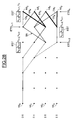
- Figures 16 and 17 show more particularly such a trellis and more particularly the stage ETG n-1 of row n-1, as well as the current stage of row n referenced ETG n .
- the set of ETA states of the trellis is therefore formed here of sixteen states or nodes nd 0 -nd 15 .
- the states of the stage ETG n-1 correspond to the hypotheses on the symbols s n-2 and s n-1 , respectively of rank n-2 and of rank n-1.
- the states nd 0 -nd 15 of the stage ETG n are representative of the assumptions on the values of the symbols s n-1 and s n , respectively of rank n-1 and of rank n.
- the states or nodes nd 0 -nd 15 of the stage ETG n can be reached from the states nd 0 -nd 15 of the stage ETG n-1 by paths or transitions TR (FIG. 17), in function of the assumption made on the value of the symbol s n .
- the estimation means MEST comprise (FIG. 3) calculation means MCL able to calculate for the different states of the current stage ETG n of the trellis the different cumulative metrics.
- the cumulative metric of the node nd 0 of the stage ETG n resulting from the node nd 0 of the stage ETG n-1 by the transition TR 0 is equal to the sum of the cumulative metric of the node Nd 0 of the stage ETG n-1 and the transition metric associated with the transition TR 0 .
- the cumulative metrics can be information of errors accumulated between the observed values and the expected values of the samples (on the basis of an assumption about the values of the symbols).
- the transition or branch metric MTR n can be a so-called "Euclidean" metric such as that defined by formula (IV) below:
- the cumulative metrics can be information of cumulative similarities between the observed values and the expected values of the samples (on the basis of an assumption about the values of the symbols).
- Such a modified transition or branch metric is for example that defined by the formula below: where y n is the output of the matched filter (obtained from the samples received r n ), Re denotes the real part, and where x n denotes the autocorrelation function of the channel (concealed from the coefficients c i of the impulse response ):
- Such a modified metric is used for example in a so-called receiver "Of Ungerboeck", such as that described in the article entitled “Unification of MLSE Receivers and Extension to Time-Varying Channels ", Gregory E. Bottomley, IEEE Transactions on Communications, Vol. 46, N ° 4, April 1998.
- the skilled person can refer to this article for more details on this modified metric.
- the calculation means will therefore calculate four cumulative metrics for the state nd 0 of the stage ETG n by applying the formulas (III) and (IV) above (in the case of a Euclidean metric) using respectively the cumulative metrics of nodes nd 0 , nd 4 , nd 8 and nd 12 of the stage ETG n-1 as well as the metrics of transitions MTR of the transitions TR 0 , TR 4 , TR 8 and TR 12 .
- the minimum (in the case of a Euclidean metric) or maximum (in the case of a modified metric) cumulative metric will be chosen for the node nd 0 of the stage ETG n for the purpose of progression in the trellis towards the ETG stage n + 1 .
- the means of estimation will make a unique decision on the value of the symbol of rank n-L + 1 (here the symbol of rank n-2), and will affect this unique decision of a symbol confidence index.
- the MEST estimation means include MPT partitioning means capable, taking into account the sample of rank n, to partition into M groups all the transitions arriving at the different states of the current stage ETG n of the trellis, each group containing all the transitions from the states of the previous stage associated with one of the M possible values of the symbol of rank n-L + 1 (steps 80 and 81, FIG. 8).
- a first group of transitions GR0 (FIG. 18) represented in bold type, corresponds to the transitions originating from the states of the stage ETG n-1 associated with the value 00 of the symbol s n-2 .
- the group of transitions GR1 (FIG. 19) contains all the transitions coming from the states of the stage ETG n-1 associated with the value 01 of the symbol s n-2 .
- the GR2 group ( Figure 20) contains all the transitions from the states of the ETG stage n-1 associated with the value 10 of the symbol s n-2 and the GR3 group ( Figure 21) contains all the transitions from the states of l 'ETG stage n-1 associated with the value 11 of the symbol s n-2 .
- the calculation means MCL determine, for each of the groups GR0-GR3, the different cumulative metrics for the different states nd 0 -nd 15 of the stage ETG n of the trellis. This calculation is performed using the formulas (III) and (IV) above or the formulas (III) and (V) above depending on the branch metric used. As indicated above, for the purpose of progression in the trellis, one and only one surviving path is selected for each node.
- the MEST estimation means also include means for MDT determination able to determine in each group that of the transitions which leads to the affected state of the extreme cumulative metric.
- the means of determination will detect (step 82, figure 8) in each group, that of the transitions which leads to the affected state of the minimum cumulative metric.
- the means of determination will determine (step 83, figure 8) in each group, that of transitions which leads to the affected state of the maximum cumulative metric.
- transition TR0 in the group GR0 which leads to the cumulative metric minimum (or maximum as the case may be), while this is the transition TR1 in the GR1 group, of the TR2 transition in the GR2 group, and of the TR3 transition in the GR3 group.
- the MEST estimation means then comprise decision-making means MPD (FIG. 3) capable of making a single decision on the value of the symbol s n-2 by detecting the group associated with the extremum of these M extreme cumulative metrics (step 86, figure 8).
- MPD decision-making means MPD
- the decision-making means will detect, in the case of a branch metric of the “error information” type (Euclidean metric for example) , the weakest of the four cumulative metrics, respectively associated with states nd 1 , nd 5 , nd 8 and nd 11 of stage ETG n .
- error information Error information
- the decision-making means will detect the larger of these four cumulative metrics.
- the decision-making means decide that the symbol of rank n-L + 1 (in this case n-2) has the value 10 (i.e. the value 3 in decimal).
- the MPD decision-making means comprise (FIG. 4) a STR subtractor capable of calculate the difference between the two minimum cumulative metrics M0 and M1 (step 90, Figure 9) developed by the means of determination.
- the MPD decision-making means also include, in addition to said STR subtractor, an SGN sign operator, capable of determining the sign of the difference between the two minimum cumulative metrics M0 and M1 (step 91). The sign of this difference then provides said single decision. In other words, if the sign is positive, the symbol of rank n-L + 1 is equal to the value +1, while if the sign is negative, the value of this symbol is equal to -1.
- branch metrics are modified metrics of the "likeness information" type.
- M0 and M1 denote the two maximum cumulative metrics delivered by the means of determination.
- FIGS. 5 and 10 illustrate decision-making as to the value of the symbol of rank n-L + 1, in the case of an M-ary modulation (M> 2) and in the case where a branch metric of the type "Error information" (Euclidean metric for example) is used.
- the decision-making means MPD comprise first selection means SEL1 capable of making a first selection of the lowest of the M minimum cumulative metrics M0, M1, M2, M3 (step 100, FIG. 10) delivered by the means of determination.
- These minimum cumulative metrics M0-M3 are, in the example illustrated in FIG. 22, those assigned to the states nd 1 , nd 5 , nd 8 and nd 11 of the stage ETG n .
- the weakest metric is the metric M2, that is to say the one assigned to node nd 8 .
- step 101 results (step 101, FIG. 10) in making a decision on the value the rank symbol n-L + 1, as explained above.
- the first selection means SEL1 this time determine (step 110, FIG. 11) the greater of the M maximum cumulative metrics delivered by the means of determination.
- the metrics M0, M1, M2 and M3 are the maximum cumulative metrics in each of the groups and that the the largest maximum cumulative metric is again the metric M2, which makes it possible to take the decision on the value of the symbol of rank n-L + 1 (step 111, Figure 11) in a similar manner to that which has already been explained above.
- the MEST estimation means include first MEB1 production means ( Figure 3) capable of developing from the extreme cumulative M metrics (minimum or maximum) an index of confidence-symbol assigned to the single decision on the value of the symbol of rank n-L + 1.
- the first MEB1 production means include the STR subtractor ( Figure 4) and a absolute value operator VBS. Indeed, the absolute value of the calculated difference by the subtractor (step 92, FIG. 9) supplies the value of said symbol confidence index.
- the first means of preparation comprise second means of selection SEL2 (figure 5). These second selection means perform, among the M-1 metrics cumulative minimum remaining (M0, M1, M3, Figure 10) not selected after the first selection 100 made by the first selection means SEL1, the lower of these remaining minimum cumulative M-1 metrics (step 102, figure 10).
- the minimum cumulative metric thus selected in step 102 is the metric M0 corresponding to the transition TR0 leading to the node nd 1 of the stage ETG n .
- the first means of development then include a STR subtractor (figure 5) able to calculate (step 103, figure 10) the difference between the two metrics cumulative minimum respectively from the first and second selections, in this case the metrics M0 and M2.
- step 104 provides the value of said symbol confidence index.
- the branch metric is an information metric of resemblance.
- the second selection means carry out the second selection from the remaining maximum cumulative M-1 metrics not selected after the first selection, from the largest of these M-1 maximum remaining cumulative metrics (step 112, figure 11).
- the invention thus makes it possible to obtain decisions on the symbols with a delay equal in the general case to k (L-1 in a trellis with M L-1 states), which is a lesser delay compared to the delay of a Viterbi algorithm of the prior art. Furthermore, the memory gain is considerable. In fact, in the invention, it is only necessary to have a storage vector for the current stage and the preceding stage of the trellis which stores the cumulative metrics. It is no longer necessary to store, as in the prior art, the symbol confidence indices on a block of 5L samples.
- confidence-bit indices are also assigned to each of the bits of the rank symbol n-L + 1 elected after taking decision on its value.
- the invention aims to remedy this gap.
- the device comprises second means of preparation MEB2 (FIGS. 6 and 7) capable of developing a confidence index-bit for each of the bits of the rank symbol n + L-1 elected after said single decision-making.
- second means of preparation MEB2 use said elected symbol SEU and at least one auxiliary symbol produced from the elected symbol by complementing at least the value of the bit considered (FIGS. 12 to 15).
- the second MEB2 production means include (FIG. 6) auxiliary production means capable of producing a single auxiliary SAX symbol in complementing only the value of the bit considered while leaving the values of the other bits of the elected symbol.
- these auxiliary production means can be trained an MX multiplexer, connected to the decision-making means and capable of select the bit considered of the elected symbol SEU for which one wishes to develop a confidence-bit index.
- the auxiliary production means then also include means CMP allowing to complement the value of the bit delivered by the MX multiplexer.
- auxiliary symbol SAX For example, we can also refer to figure 24, on which we consider that the symbol elected SEU is the symbol 10. We also suppose that we want to develop an index of confidence-bit for the bit of value 1 of the symbol SEU. The SAX symbol is therefore the symbol 00.
- auxiliary selection means SELX1 are able to select the minimum cumulative metric associated with the group of transitions to which said auxiliary symbol SAX belongs (step 122, FIG. 12).
- the symbol SAX belongs to the group GR0 and the minimum cumulative metric associated with the group GR0 is that associated with step nd 1 corresponding to the transition TR0.
- An auxiliary subtractor STRX then performs the difference between the minimum cumulative metric associated with the group of transitions to which the elected symbol SEU belongs (i.e. the cumulative metric associated with the state nd 8 of the stage ETG n (figure 24)) and the minimum cumulative metric associated with the group of transitions to which said auxiliary symbol belongs (i.e. the cumulative metric associated with state nd 1 ), the result of this difference providing the value of said confidence index -bit associated with the bit considered of the symbol SEU (step 124, FIG. 12).
- the second means of elaboration include ( Figure 7) MEBX auxiliary processing means this time suitable for elaborate a set of auxiliary symbols SAXj by complementing the value of bit considered of the elected symbol SEU and conferring on the other bits of the symbol elected ONLY all possible values (steps 130, 131 and 132, Figure 13).
- the means of development auxiliary include an MX multiplexer capable of selecting the bit considered of the symbol SEU for which one wishes to establish a confidence index-bit as well as a CMP means capable of complementing only the value of this bit considered.
- auxiliary symbols SAX1 and SAX2 are then developed by complementing bit 1 to 0 and giving the other bit either the value 0, or the value 1.
- the auxiliary symbol SAX1 has the value 00
- the symbol SAX2 auxiliary has the value 01.
- First auxiliary selection means SELX1 then select respectively the minimum cumulative metrics associated with the group of transitions to which the auxiliary symbols SAX1 and SAX2 respectively belong.
- auxiliary symbols SAX1 and SAX2 belong to the groups GR0 and GR1, and the minimum cumulative metrics are those respectively associated with states nd 1 and nd 5 (( Figure 25); and step 133 ( Figure 13)).
- the second auxiliary selection means SELAX2 selects the lowest of the minimum cumulative metrics respectively selected by the first auxiliary selection means (step 134, FIG. 13). It is assumed, for example, that the weakest metric is that assigned to state nd 1 ( Figure 25).
- An auxiliary subtractor STRX then makes the difference between the minimum cumulative metric associated with the transition group to which said elected symbol SEU belongs (that is to say the cumulative metric associated with the state nd 8 ) and the minimum cumulative metric selected by the second auxiliary selection means, that is to say the metric associated with the transition TR0.
- the result of this difference (step 135, FIG. 13) provides the value of said confidence-bit index.
- MEST estimation means and means MEB2 can be realized for example in a signal processing processor, the processing carried out within these means being carried out in software.
- These treatments are then in the form of program codes which can be easily written by a person skilled in the art from the functional definition of these treatments which has just been given above.
- the program code means are then by example stored in a read-only memory associated with the processor. That said, a entirely hardware realization of the MEST and MEB2 means also possible, for example in the form of a specific integrated circuit (ASIC).
- ASIC application specific integrated circuit
- the invention is not limited to the application of the equalization of a channel transmission. Indeed, it applies more generally to any estimate of values successive numerical symbols which can each take M possible values different, from successive values of digital samples each of which results from the combination of at most L successive symbols, and comprising a stage / stage progression in a Viterbi type trellis with all states of all floors are respectively assigned cumulative metrics. This can in particular also be the case when the signal is voluntarily modified on transmission, for purposes protection against errors for example, or encryption.
- the invention is not limited to the variant embodiments and implementation which have just been described. Indeed, the invention applies in particular regardless of the number of trellis states (full trellis or reduced trellis), that the metric used is the Euclidean metric, a modified metric at the end of the suitable filter or any other metric.
- the Viterbi algorithm used with a full trellis can become difficult to achieve when the temporal dispersion induced by the channel transmission is too large (L is too large) or when the order of the modulation increases (M> 2).
- This algorithm is modified according to the invention at the decision-making level on symbol values.
- the number k can be considered as the apparent memory of the channel.
- the states of the stage ETG n-1 correspond to the hypotheses on the symbols s n-2 and s n-1 .
- an EST estimate of the symbols missing due to the reduction of the trellis is associated.
- the estimate EST is an estimate on the symbols s n-4 and s n-3 .
- each symbol is worth 0 or 1, for example.
- the node nd 0 is assigned the values 00 corresponding respectively to the two symbols s n-1 , s n of the stage ETG n , or else to the two symbols s n-3 , s n-2 of the stage ETG n -2 , etc ...
- survivor defined as being that which leads, for the considered state of the stage ETG n , obtaining a minimum or maximum cumulative metric depending on the metric used.
- FIG. 26 for the sake of simplification only the surviving paths leading to the stage ETG n-1 have been shown , and in solid lines those leading to the stage ETG n (the competing paths and not selected at the ETG stage n are shown in dashes)
- stage ETG n We also associate with this state considered of stage ETG n a new label EST containing the estimation of the missing symbols s n-3 and s n-2 .
- the node or state from which the surviving path has led to the considered state of the stage ETG n is determined .
- the node nd 0 of the stage ETG n is reached by the transition (surviving path) TR 0 coming from the node nd 0 of the stage ETG n-1 .
- the means of decision-making will, by analogy with a full trellis, make a decision unique on the rank symbol n-k (n-2 in the example described) when taking account of the sample of rank n. This will, as already explained above, avoid waiting for a relatively long time corresponding to 5L samples to make a decision on the rank symbol n-5L-k, going up the path leading to the node whose cumulative metric is minimum or maximum.
- the transitions connecting the nodes of the stage ETG n-1 to the nodes of the stage ETG n are divided into two groups.
- the first group corresponding to the value 0 of the symbol of rank nk (here n-2) is formed of the transitions TR 0 , TR 1 , TR 2 and TR 3 ( Figure 27).
- the second group, illustrated in FIG. 28, corresponding to the value 1 of the symbol s nk , is formed of the transitions TR 4 , TR 5 , TR 6 and TR 7 .
- the decision taken on the value of the symbol s n-2 is different from the four values of the symbols s n-2 contained in the four EST labels, and which are used for the progression in the trellis for the choice of the surviving path, it is particularly advantageous to use, in another alternative embodiment, the value of the symbol s n-2 taken during the decision for the calculation of the labels and the progression in the trellis .
- the value of the symbol s n-2 taken during the decision for the calculation of the labels and the progression in the trellis it is necessary, at each step, to memorize as many labels as there are states in the trellis. And, the longer the channel, the larger the label. And this also results in numerous memory accesses, which requires durations which can prove to be penalizing.
- the states of the current stage of rank n of the trellis correspond to the hypotheses on the k symbols of rank n to n-k + 1.
- the decision-making means have decided that the value of the symbol of rank nk (here n-2) is equal to 0. Consequently, l 'EST tag assigned to all states of the ETG stage n will contain the value of the symbol s n-3 resulting from the single decision made during the previous step in the trellis, as well as the value of the decision on the symbol s n-2 .
- transitions TR 0 , TR 1 , TR 2 and TR 3 from the states nd 0 and nd 1 corresponding to the value 0 of the symbol s n-2 will be selected.
- the other transitions, corresponding to the value 1 of the symbol s n-2 namely the transitions TR 4 , TR 5 , TR 6 and TR 7 , will not be selected.
- the new cumulative metrics of the states of the stage ETG n will therefore be calculated from the transitions thus selected.
- the progression in the trellis is here conditioned to successive decisions on symbol values.
- the fact of working at the output of the adapted filter makes it possible to no longer involve the phase of the propagation channel. So that the channel is at minimum phase, maximum phase or whatever the phase is between these two extreme values, the signal is always exactly the same at the output of the matched filter.
- the modification of the metric to be made to take into account the presence of the adapted filter also goes in the direction of a simplification. Indeed, with a metric like "similarity information", some terms can be precalculated so that the final calculation for progression in the trellis does not include no multiplication (against two multiplications for the Euclidean metric), this which allows an easier hardware implementation of the algorithm.
Landscapes
- Engineering & Computer Science (AREA)
- Power Engineering (AREA)
- Computer Networks & Wireless Communication (AREA)
- Signal Processing (AREA)
- Error Detection And Correction (AREA)
- Cable Transmission Systems, Equalization Of Radio And Reduction Of Echo (AREA)
Priority Applications (3)
| Application Number | Priority Date | Filing Date | Title |
|---|---|---|---|
| EP01112095A EP1213884B1 (de) | 2000-12-04 | 2001-05-29 | Verfahren und Vorrichtung zur Schätzung der aufeinanderfolgenden Werte digitaler Symbole insbesondere für die Entzerrung eines Datenübertragungskanals in der Mobiltelephonie |
| US10/006,995 US7054392B2 (en) | 2000-12-04 | 2001-12-03 | Process and device for estimating the successive values of digital symbols, in particular for the equalization of an information transmission channel in mobile telephony |
| JP2001368896A JP4076765B2 (ja) | 2000-12-04 | 2001-12-03 | デジタル・シンボルの連続値を推定する方法および装置 |
Applications Claiming Priority (3)
| Application Number | Priority Date | Filing Date | Title |
|---|---|---|---|
| EP00125395A EP1211857A1 (de) | 2000-12-04 | 2000-12-04 | Verfahren und Vorrichtung zur Schätzung der aufeinanderfolgenden Werte digitaler Symbole insbesondere für die Entzerrung eines Datenübertragungskanals in der Mobiltelefonie |
| EP00125395 | 2000-12-04 | ||
| EP01112095A EP1213884B1 (de) | 2000-12-04 | 2001-05-29 | Verfahren und Vorrichtung zur Schätzung der aufeinanderfolgenden Werte digitaler Symbole insbesondere für die Entzerrung eines Datenübertragungskanals in der Mobiltelephonie |
Publications (2)
| Publication Number | Publication Date |
|---|---|
| EP1213884A1 true EP1213884A1 (de) | 2002-06-12 |
| EP1213884B1 EP1213884B1 (de) | 2007-03-14 |
Family
ID=26071606
Family Applications (1)
| Application Number | Title | Priority Date | Filing Date |
|---|---|---|---|
| EP01112095A Expired - Lifetime EP1213884B1 (de) | 2000-12-04 | 2001-05-29 | Verfahren und Vorrichtung zur Schätzung der aufeinanderfolgenden Werte digitaler Symbole insbesondere für die Entzerrung eines Datenübertragungskanals in der Mobiltelephonie |
Country Status (3)
| Country | Link |
|---|---|
| US (1) | US7054392B2 (de) |
| EP (1) | EP1213884B1 (de) |
| JP (1) | JP4076765B2 (de) |
Families Citing this family (6)
| Publication number | Priority date | Publication date | Assignee | Title |
|---|---|---|---|---|
| US7050817B2 (en) * | 2003-04-24 | 2006-05-23 | Locus Location Systems, Llc | Locating method and system |
| US7206363B2 (en) | 2003-06-24 | 2007-04-17 | Intersymbol Communications, Inc. | Method and apparatus for delayed recursion decoder |
| GB0417292D0 (en) * | 2004-08-03 | 2004-09-08 | Ttp Communications Ltd | Method of and apparatus for improving computational efficiency in sequence estimation |
| KR100813260B1 (ko) | 2005-07-13 | 2008-03-13 | 삼성전자주식회사 | 코드북 탐색 방법 및 장치 |
| US7365671B1 (en) * | 2006-10-10 | 2008-04-29 | Seagate Technology Llc | Communication channel with undersampled interpolative timing recovery |
| US8102938B2 (en) * | 2008-04-22 | 2012-01-24 | Finisar Corporation | Tuning system and method using a simulated bit error rate for use in an electronic dispersion compensator |
Citations (3)
| Publication number | Priority date | Publication date | Assignee | Title |
|---|---|---|---|---|
| US5144644A (en) * | 1989-10-13 | 1992-09-01 | Motorola, Inc. | Soft trellis decoding |
| US5375129A (en) * | 1990-07-19 | 1994-12-20 | Technophone Limited | Maximum likelihood sequence detector |
| EP0858196A1 (de) * | 1997-02-06 | 1998-08-12 | Alcatel | Entzerrer und Kanaldekoder |
Family Cites Families (4)
| Publication number | Priority date | Publication date | Assignee | Title |
|---|---|---|---|---|
| US6347125B1 (en) * | 1999-01-11 | 2002-02-12 | Ericsson Inc. | Reduced complexity demodulator for multi-bit symbols |
| US6622283B1 (en) * | 2000-01-28 | 2003-09-16 | Nec Electronics, Inc. | Digital signal processor decoding of convolutionally encoded symbols |
| US6707849B1 (en) * | 2000-02-08 | 2004-03-16 | Ericsson Inc. | Methods, receivers and equalizers having increased computational efficiency |
| US6829297B2 (en) * | 2001-06-06 | 2004-12-07 | Micronas Semiconductors, Inc. | Adaptive equalizer having a variable step size influenced by output from a trellis decoder |
-
2001
- 2001-05-29 EP EP01112095A patent/EP1213884B1/de not_active Expired - Lifetime
- 2001-12-03 US US10/006,995 patent/US7054392B2/en not_active Expired - Lifetime
- 2001-12-03 JP JP2001368896A patent/JP4076765B2/ja not_active Expired - Fee Related
Patent Citations (3)
| Publication number | Priority date | Publication date | Assignee | Title |
|---|---|---|---|---|
| US5144644A (en) * | 1989-10-13 | 1992-09-01 | Motorola, Inc. | Soft trellis decoding |
| US5375129A (en) * | 1990-07-19 | 1994-12-20 | Technophone Limited | Maximum likelihood sequence detector |
| EP0858196A1 (de) * | 1997-02-06 | 1998-08-12 | Alcatel | Entzerrer und Kanaldekoder |
Non-Patent Citations (1)
| Title |
|---|
| MUELLER S H ET AL: "REDUCED-STATE SOFT-OUTPUT TRELLIS-EQUALIZATION INCORPORATING SOFT FEEDBACK", GLOBAL TELECOMMUNICATIONS CONFERENCE (GLOBECOM),US,NEW YORK, IEEE, 18 November 1996 (1996-11-18), pages 95 - 100, XP000742133, ISBN: 0-7803-3337-3 * |
Also Published As
| Publication number | Publication date |
|---|---|
| JP4076765B2 (ja) | 2008-04-16 |
| US7054392B2 (en) | 2006-05-30 |
| US20020126775A1 (en) | 2002-09-12 |
| JP2002261629A (ja) | 2002-09-13 |
| EP1213884B1 (de) | 2007-03-14 |
Similar Documents
| Publication | Publication Date | Title |
|---|---|---|
| EP0827284B1 (de) | Informationsbits-Übertragungsverfahren mit Fehlerkorrektur-Kodierung, Kodier- und Dekodiervorrichtung dafür | |
| EP0946014B1 (de) | Verfahren zur Detektion einer Symbolfolge aus einem empfangenen Signal, und Viterbi-Prozessor zur Durchführung des Verfahrens | |
| FR2798542A1 (fr) | Recepteur a multiplexage par repartition en frequences orthogonales avec estimation iterative de canal et procede correspondant | |
| FR2730370A1 (fr) | Dispositif de reception de signaux numeriques a structure iterative, module et procede correspondants | |
| FR2866167A1 (fr) | Egaliseur et procede d'actualisation de coefficients de filtre | |
| EP1168739A1 (de) | Verfahren und Vorrichtung zur Schätzung der Impulsantwort eines Übertragungskanals, insbesondere für ein zellulares Mobiltelefon | |
| EP2915302B1 (de) | Verfahren und vorrichtung zur demodulation von q-gfsk signalen | |
| FR3050343A1 (fr) | Methode de decodage a inversion d'un code polaire | |
| WO2002011378A1 (fr) | Procede de traitement d'un signal numerique en entree d'un egaliseur de canal | |
| FR2783120A1 (fr) | Procede d'egalisation numerique, et recepteur de radiocommunication mettant en oeuvre un tel procede | |
| FR2794589A1 (fr) | Procede de communications radiomobiles amrt iteratif | |
| EP1213884B1 (de) | Verfahren und Vorrichtung zur Schätzung der aufeinanderfolgenden Werte digitaler Symbole insbesondere für die Entzerrung eines Datenübertragungskanals in der Mobiltelephonie | |
| FR2832876A1 (fr) | Procede et dispositif d'estimation de signeaux a probabilite maximale sur la base d'un treillis, pour l'estimation d'un canal commun aveugle et pour la detection de signaux | |
| EP1066706B1 (de) | Verfahren zur digitalen entzerrung und empfänger zur ausführung dieses verfahrens | |
| EP1211857A1 (de) | Verfahren und Vorrichtung zur Schätzung der aufeinanderfolgenden Werte digitaler Symbole insbesondere für die Entzerrung eines Datenübertragungskanals in der Mobiltelefonie | |
| EP1792463B1 (de) | Verfahren zur schätzung der phase und des pegels von über einen qam-modulierten übertragungskanal übertragenen sdaten | |
| EP2074705B1 (de) | Verfahren und Vorrichtungen um die Übersprechungskoeffizienten bei Inbetriebnahme einer Leitung zu schätzen | |
| EP3912317B1 (de) | Verfahren zum empfangen eines soqpsk-tg-signals mit pam-zerlegung | |
| EP0724346B1 (de) | Verfahren zur Bestimmung des Phasenfehlers in einem digitalen Datenempfänger | |
| EP1212873B1 (de) | Verfahren zur gemeinsamen dekodierung und entzerrung eines durch ein gitter definiertes kodegesichertes signal | |
| EP1162802A1 (de) | Entzerrer, eine Kanalumwandlung verwendend. | |
| FR2711028A1 (fr) | Procédé et dispositif de démodulation cohérente par blocs de signaux complexes modulés en phase. | |
| FR2849306A1 (fr) | Recepteur a turbo-estimation de canal a convergence optimisee | |
| EP0925671B1 (de) | Informationsübertragungsverfahren | |
| EP0858196A1 (de) | Entzerrer und Kanaldekoder |
Legal Events
| Date | Code | Title | Description |
|---|---|---|---|
| PUAI | Public reference made under article 153(3) epc to a published international application that has entered the european phase |
Free format text: ORIGINAL CODE: 0009012 |
|
| AK | Designated contracting states |
Kind code of ref document: A1 Designated state(s): AT BE CH CY DE DK ES FI FR GB GR IE IT LI LU MC NL PT SE TR |
|
| AX | Request for extension of the european patent |
Free format text: AL;LT;LV;MK;RO;SI |
|
| 17P | Request for examination filed |
Effective date: 20021205 |
|
| AKX | Designation fees paid |
Designated state(s): DE FR GB IT |
|
| GRAC | Information related to communication of intention to grant a patent modified |
Free format text: ORIGINAL CODE: EPIDOSCIGR1 |
|
| GRAP | Despatch of communication of intention to grant a patent |
Free format text: ORIGINAL CODE: EPIDOSNIGR1 |
|
| GRAS | Grant fee paid |
Free format text: ORIGINAL CODE: EPIDOSNIGR3 |
|
| GRAA | (expected) grant |
Free format text: ORIGINAL CODE: 0009210 |
|
| AK | Designated contracting states |
Kind code of ref document: B1 Designated state(s): DE FR GB IT |
|
| REG | Reference to a national code |
Ref country code: GB Ref legal event code: FG4D Free format text: NOT ENGLISH |
|
| REF | Corresponds to: |
Ref document number: 60127227 Country of ref document: DE Date of ref document: 20070426 Kind code of ref document: P |
|
| GBT | Gb: translation of ep patent filed (gb section 77(6)(a)/1977) |
Effective date: 20070511 |
|
| PGFP | Annual fee paid to national office [announced via postgrant information from national office to epo] |
Ref country code: IT Payment date: 20070524 Year of fee payment: 7 |
|
| PLBE | No opposition filed within time limit |
Free format text: ORIGINAL CODE: 0009261 |
|
| STAA | Information on the status of an ep patent application or granted ep patent |
Free format text: STATUS: NO OPPOSITION FILED WITHIN TIME LIMIT |
|
| 26N | No opposition filed |
Effective date: 20071217 |
|
| PGFP | Annual fee paid to national office [announced via postgrant information from national office to epo] |
Ref country code: FR Payment date: 20070529 Year of fee payment: 7 |
|
| PGFP | Annual fee paid to national office [announced via postgrant information from national office to epo] |
Ref country code: DE Payment date: 20080514 Year of fee payment: 8 |
|
| PGFP | Annual fee paid to national office [announced via postgrant information from national office to epo] |
Ref country code: GB Payment date: 20080424 Year of fee payment: 8 |
|
| REG | Reference to a national code |
Ref country code: FR Ref legal event code: ST Effective date: 20090119 |
|
| PG25 | Lapsed in a contracting state [announced via postgrant information from national office to epo] |
Ref country code: FR Free format text: LAPSE BECAUSE OF NON-PAYMENT OF DUE FEES Effective date: 20080602 |
|
| PG25 | Lapsed in a contracting state [announced via postgrant information from national office to epo] |
Ref country code: IT Free format text: LAPSE BECAUSE OF NON-PAYMENT OF DUE FEES Effective date: 20080529 |
|
| GBPC | Gb: european patent ceased through non-payment of renewal fee |
Effective date: 20090529 |
|
| PG25 | Lapsed in a contracting state [announced via postgrant information from national office to epo] |
Ref country code: GB Free format text: LAPSE BECAUSE OF NON-PAYMENT OF DUE FEES Effective date: 20090529 |
|
| PG25 | Lapsed in a contracting state [announced via postgrant information from national office to epo] |
Ref country code: DE Free format text: LAPSE BECAUSE OF NON-PAYMENT OF DUE FEES Effective date: 20091201 |