EP1213635A2 - Prädiktive Regelung eines Generatorausgangs - Google Patents
Prädiktive Regelung eines Generatorausgangs Download PDFInfo
- Publication number
- EP1213635A2 EP1213635A2 EP01124179A EP01124179A EP1213635A2 EP 1213635 A2 EP1213635 A2 EP 1213635A2 EP 01124179 A EP01124179 A EP 01124179A EP 01124179 A EP01124179 A EP 01124179A EP 1213635 A2 EP1213635 A2 EP 1213635A2
- Authority
- EP
- European Patent Office
- Prior art keywords
- point
- drive
- drive point
- sequence
- programmable
- Prior art date
- Legal status (The legal status is an assumption and is not a legal conclusion. Google has not performed a legal analysis and makes no representation as to the accuracy of the status listed.)
- Withdrawn
Links
Images

Classifications
-
- G—PHYSICS
- G05—CONTROLLING; REGULATING
- G05B—CONTROL OR REGULATING SYSTEMS IN GENERAL; FUNCTIONAL ELEMENTS OF SUCH SYSTEMS; MONITORING OR TESTING ARRANGEMENTS FOR SUCH SYSTEMS OR ELEMENTS
- G05B19/00—Program-control systems
-
- G—PHYSICS
- G05—CONTROLLING; REGULATING
- G05B—CONTROL OR REGULATING SYSTEMS IN GENERAL; FUNCTIONAL ELEMENTS OF SUCH SYSTEMS; MONITORING OR TESTING ARRANGEMENTS FOR SUCH SYSTEMS OR ELEMENTS
- G05B19/00—Program-control systems
- G05B19/02—Program-control systems electric
- G05B19/18—Numerical control [NC], i.e. automatically operating machines, in particular machine tools, e.g. in a manufacturing environment, so as to execute positioning, movement or co-ordinated operations by means of program data in numerical form
- G05B19/19—Numerical control [NC], i.e. automatically operating machines, in particular machine tools, e.g. in a manufacturing environment, so as to execute positioning, movement or co-ordinated operations by means of program data in numerical form characterised by positioning or contouring control systems, e.g. to control position from one programmed point to another or to control movement along a programmed continuous path
-
- G—PHYSICS
- G05—CONTROLLING; REGULATING
- G05B—CONTROL OR REGULATING SYSTEMS IN GENERAL; FUNCTIONAL ELEMENTS OF SUCH SYSTEMS; MONITORING OR TESTING ARRANGEMENTS FOR SUCH SYSTEMS OR ELEMENTS
- G05B19/00—Program-control systems
- G05B19/02—Program-control systems electric
- G05B19/04—Program control other than numerical control, i.e. in sequence controllers or logic controllers
- G05B19/042—Program control other than numerical control, i.e. in sequence controllers or logic controllers using digital processors
-
- G—PHYSICS
- G05—CONTROLLING; REGULATING
- G05B—CONTROL OR REGULATING SYSTEMS IN GENERAL; FUNCTIONAL ELEMENTS OF SUCH SYSTEMS; MONITORING OR TESTING ARRANGEMENTS FOR SUCH SYSTEMS OR ELEMENTS
- G05B21/00—Systems involving sampling of the variable controlled
- G05B21/02—Systems involving sampling of the variable controlled electric
-
- G—PHYSICS
- G05—CONTROLLING; REGULATING
- G05B—CONTROL OR REGULATING SYSTEMS IN GENERAL; FUNCTIONAL ELEMENTS OF SUCH SYSTEMS; MONITORING OR TESTING ARRANGEMENTS FOR SUCH SYSTEMS OR ELEMENTS
- G05B2219/00—Program-control systems
- G05B2219/30—Nc systems
- G05B2219/34—Director, elements to supervisory
- G05B2219/34119—Function generator, filter after interpolator to control position error
-
- G—PHYSICS
- G05—CONTROLLING; REGULATING
- G05B—CONTROL OR REGULATING SYSTEMS IN GENERAL; FUNCTIONAL ELEMENTS OF SUCH SYSTEMS; MONITORING OR TESTING ARRANGEMENTS FOR SUCH SYSTEMS OR ELEMENTS
- G05B2219/00—Program-control systems
- G05B2219/30—Nc systems
- G05B2219/34—Director, elements to supervisory
- G05B2219/34122—Function, profile generator
Definitions
- the present invention relates generally to generators that have a programmable output, and in particular to generators that employ digital sampling techniques to control a programmable output.
- Generators that provide a programmable output having pulse capability generally employ either an analog control loop or a high-speed digital control loop in order to provide fast rise and fall times.
- the response time is largely a function of the sample rate and the group delays of the analog to digital (A/D) and digital to analog (D/A) converters. Therefore, a lower limit is placed on the response time of a digitally sampled control loop.
- Conventional digital control loops have been unable to provide response times that are not limited by the sample rates of the A/D and D/A that are used in the circuit.
- using a very fast A/D and DSP having a sufficient sample rate is expensive and requires additional circuit area.
- the present control circuit and method extends the operating range of digitally sampled control loops without resorting to expensive A/D converters by controlling the. programmable output of a generator.
- the output of the loop controller is driven to a predicted drive point which forces the programmable output to approximately the desired set point.
- the programmable output includes an output level having a corresponding set point.
- the generator has a drive input that is driven to an actual drive point for controlling the output level of the programmable output.
- a set point corresponding to a requested output level is determined.
- a predicted drive point is then determined.
- the actual drive point of the generator drive input is forced to the predicted drive point.
- the output level of the programmable output is then sensed.
- a digital output signal that is representative of the sensed output level is generated.
- the actual drive point of the generator drive input is controlled based on the digital output signal, such that the output level of the programmable output is controlled.
- the actual drive point corresponding to the requested output level is then stored.
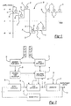
- the output waveform 10 comprises numerous sequence steps 12 that are preselected by a user.
- each sequence step 12 defines a time period over which a predefined output such as voltage, current, or power is maintained.
- Each sequence step 12 is defined by a sequence point 14 and a set point 16.
- the sequence point 14 is generally an increasing numeric which is assigned to succeeding sequence steps.
- the set point 16 describes the desired amplitude of the output for the corresponding sequence step 12.
- a user merely selects a predefined output. There is no sequence step or time period associated with the selected output.
- a presently preferred embodiment of a predictive control circuit 20 is shown in combination with a generator 22. While the present invention is shown and described as controlling an electro-chemical deposition (ECD) generator 22, it will be appreciated that this application for the control circuit 20 is merely exemplary and that the generator 22 could be any controllable power source.
- the predictive control circuit 20 operates by cycling a programmable output 24 through a predetermined set of sequence steps.
- a sequence step in the preferred embodiment is a minimum of 100 usec, however the invention encompasses variable as well as fixed time periods, and also time periods that are greater or lesser than 100 usec. As illustrated in Figure 1, each sequence step is defined by a sequence point and a set point.
- the set points are stored relative to sequence points in a sequence point array 26.
- the scope of the invention encompasses storing the set points in discrete memory locations as well as receiving set points that are not associated with a sequence step.
- a sequence point controller 28 for determining the set point that corresponds with a specific sequence point or requested output.
- the sequence point controller 28 provides the set point, the corresponding sequence point, or the requested output to a drive point controller 30 and a loop controller 32.
- the drive point controller 30 determines a drive signal 31 to be supplied to the loop controller 32.
- the drive point controller 30 uses the sequence point provided by the sequence point controller 28 to determine a predicted drive signal to supply to the loop controller 32.
- the drive signal is described by drive points that are stored in prediction memory.
- a drive point array 34 is used to store drive points corresponding to the sequence point.
- the scope of the invention additionally contemplates using the set point or requested output either in combination with the sequence point or alone to determine an appropriate drive signal.
- the drive point controller 30 also updates the drive point information stored in the drive point array 34. Prior to changing from one sequence step to the next sequence step, the drive point controller 30 updates the drive point array 34 with a measured drive signal.
- the scope of the invention includes updating the drive point array 34 with other representations of the measured drive signal including statistical representations such as a running average, a peak value, a minimum value, and a mean value.
- the drive point controller 30 may update all the drive points in the drive point array 34.
- the updated drive point values may be interpolated from the measured drive signal using for example a linear or a least squares interpolation scheme.
- only a subset of drive values may be updated such as those that approximately correspond to the set point that is associated with the sequence step.
- the loop controller 32 provides closed loop control of the programmable output 24 once the drive signal has been driven to the predicted drive point.
- the loop controller 32 is a proportional-integral-derivative (PID) controller that is implemented in a Motorola 56303 digital signal processor.
- PID proportional-integral-derivative
- Those skilled in the art will recognize that the invention may be used with other controller configurations. It is also within the scope of the invention to replace the digital signal processor with an analog logic array or logic elements that mirror the function of the processor.
- the loop controller 32 uses the set point received from the sequence point controller 28 as a reference input.
- a converted signal input 36 that is a digital representation of the programmable output 24 is compared to the reference input, in response to which the loop controller 32 generates the drive signal 31.
- a control loop that employs digital conversion of a signal universally includes a delay time that limits the time response of the loop.
- the limited time response of the control loop is particularly troublesome in systems having a pulsed output.
- the ability of the control loop to drive the output so that the desired fast rising and falling edges of the pulsed output are created is limited by the time response.
- conventional systems design around the time response limitation by either employing an analog control loop or a high performance digital control loop (if it is fast enough) with its attendant price and size costs.
- the present invention solves the time response limitation by driving the loop controller output to a predicted drive point that forces the programmable output 24 to approximately the desired set point.
- the response of the loop controller 32 in the presently preferred embodiment is slowed-up.
- the generator 22 converts input power to the programmable output 24.
- the conversion ratio of the programmable output 24 to the input power is described by a transfer function.
- the transfer function of the generator 22 used in conjunction with the preferred embodiment is a complex non-linear ratio that includes a reciprocal of the input power. Due to the nonlinearity of the transfer function, it is difficult to calculate a predicted drive point for a given input power and a desired programmable output. Additionally, gain drifts from temperature and operating point changes, as well as load changes, further increase the complexity of calculating the drive point.
- the preferred embodiment of the present invention avoids the complexity of having to accurately calculate a predicted drive point by storing a drive point that is obtained while the programmable output 24 is being controlled by the loop controller 32.
- a sensor circuit 40 samples the programmable output 24 and detects electrical characteristics of the output 24 such as voltage, current, power, and phase.
- the sampled output is coupled to the signal converter 38 for conversion to a digital signal.
- a Motorola analog to digital converter operating at 200 kHz is employed as the signal converter 38.
- the scope of invention contemplates the use of other means for converting an analog signal to a digital signal.
- Figure 3 illustrates an exemplary waveform of the programmable output 24.
- the loop controller 32 actively regulates the programmable output 24 to an output level, X 1 , that corresponds to the set point for that sequence step or that requested output level.
- the loop controller 32 continues to regulate the output 24 until point B 1 of the waveform is reached.
- the drive point that is output from the loop controller 32 is stored in the drive point array 34.
- the drive point corresponding to the next sequence step or next requested output level is retrieved from prediction memory and used to force the drive signal to a value that causes the programmable output 24 to track the desired transition from point B 1 to point A 2 .
- the loop controller 32 again actively regulates the programmable output 24 to the set point corresponding to the corresponding sequence step or requested output level.
- the drive point is again stored in prediction memory within the drive point array 34. The drive point corresponding to the next sequence step is retrieved from prediction memory and used to force the drive input to a level that drives the programmable output 24 to the desired level.
- a set point corresponding to the sequence step or requested output level is determined.
- a predicted drive point corresponding to either the sequence step or the set point is determined, step 44.
- the actual drive point of the drive signal 31 is forced to the predicted drive point, step 46.
- Control of the programmable output 24 is then turned over to the loop controller 32, step 48.
- the loop controller 32 compares a digital representation of the programmable output 24 to the set point corresponding to the sequence step or requested output level.
- the actual drive point of the drive signal 31 is stored, step 50.
- the predicted drive point is updated with the actual drive point obtained at step 50. It is within the scope of the invention to calculate a statistical measure from the predicted drive point and the actual drive point, and to store the statistical drive point for future use as a predicted drive point.
- the process then advances to the next sequence step, step 52.
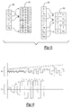
- the drive point array 34a includes set points and corresponding drive points arranged in a tabular manner.
- the sequence point array 26a includes pointers corresponding to each sequence step, each of which points to an associated set point in the drive point array 34a.
- the drive point array 34a may be either a fixed length including a predetermined number of set points or the array 34a may be dynamically expandable to include additional set points with corresponding drive points. Initial values for the additional drive points may be interpolated from existing drive points for may be initialized for a predetermined constant.
- the second configuration is similar to the first configuration with the exception that the set points are not arranged in increasing order.
- pointers from the sequence point array 26b again point to corresponding set points that are stored in the drive point array 34b. Additional pointers are included in the sequence point array 26b for every additional sequence step that is added to the programmable output 24.
- Waveform "A" depicts a softstart feature of the presently preferred embodiment of the predicted control circuit 20.
- the illustrated waveform includes 13 repeating sequence steps. By starting at zero and ramping up, stress on the load coupled to the generator 22 is significantly reduced.
- Waveform "B” illustrates a softstart feature of another embodiment of the predicted control circuit 20.
- the illustrated waveform includes five repeating sequence steps.
- the drive point is related to the set point and sequence step in a manner similar to that illustrated in the first configuration of Fig. 5.
- the set point for each sequence step is the same, resulting in a pulsating waveform.
- the predictive control circuit of the present invention extends the operating range of digitally sampled control loops for generators having a pulsed output.
- the control circuit provides an output having transition times that are not limited by delays in the loop controller.
- the techniques of the present invention permit the use of relatively low performance digital conversion circuit components to generate high-performance pulsed outputs.
- the predictive control circuit is designed with a comparatively small number of components that are less costly than high-performance components that are required in conventional circuits.
Landscapes
- Engineering & Computer Science (AREA)
- Physics & Mathematics (AREA)
- General Physics & Mathematics (AREA)
- Automation & Control Theory (AREA)
- Human Computer Interaction (AREA)
- Manufacturing & Machinery (AREA)
- Feedback Control In General (AREA)
- Control Of Eletrric Generators (AREA)
Applications Claiming Priority (2)
| Application Number | Priority Date | Filing Date | Title |
|---|---|---|---|
| US09/686,403 US6555994B1 (en) | 2000-10-11 | 2000-10-11 | Predictive control of a generator output |
| US686403 | 2000-10-11 |
Publications (2)
| Publication Number | Publication Date |
|---|---|
| EP1213635A2 true EP1213635A2 (de) | 2002-06-12 |
| EP1213635A3 EP1213635A3 (de) | 2006-11-29 |
Family
ID=24756156
Family Applications (1)
| Application Number | Title | Priority Date | Filing Date |
|---|---|---|---|
| EP01124179A Withdrawn EP1213635A3 (de) | 2000-10-11 | 2001-10-11 | Prädiktive Regelung eines Generatorausgangs |
Country Status (6)
| Country | Link |
|---|---|
| US (1) | US6555994B1 (de) |
| EP (1) | EP1213635A3 (de) |
| JP (1) | JP2002196802A (de) |
| KR (1) | KR20020028857A (de) |
| CN (1) | CN1199097C (de) |
| TW (1) | TW543281B (de) |
Families Citing this family (3)
| Publication number | Priority date | Publication date | Assignee | Title |
|---|---|---|---|---|
| JP4333022B2 (ja) * | 2000-11-10 | 2009-09-16 | 株式会社デンソー | 車両用発電機の発電制御システム |
| US6977492B2 (en) * | 2002-07-10 | 2005-12-20 | Marvell World Trade Ltd. | Output regulator |
| US9276511B2 (en) | 2014-02-04 | 2016-03-01 | Kohler Co. | Field current profile |
Family Cites Families (10)
| Publication number | Priority date | Publication date | Assignee | Title |
|---|---|---|---|---|
| US4222108A (en) * | 1978-12-01 | 1980-09-09 | Braaten Norman J | Digitally-programmed arbitrary waveform generator |
| US4451879A (en) * | 1981-10-14 | 1984-05-29 | Rca Corporation | Circuit for providing a common setpoint for manual and automatic regulation of a process control system |
| US5130920A (en) * | 1989-09-15 | 1992-07-14 | Eastman Kodak Company | Adaptive process control system, especially for control of temperature of flowing fluids |
| US5013995A (en) * | 1989-10-30 | 1991-05-07 | Sundstrand Corporation | Programmable current limit curve |
| US5153498A (en) * | 1989-11-07 | 1992-10-06 | Sundstrand Corporation | Generic control unit |
| US5170341A (en) * | 1990-10-24 | 1992-12-08 | Honeywell Inc. | Adaptive controller in a process control system and a method therefor |
| US5298851A (en) * | 1992-05-12 | 1994-03-29 | Transpo Electronics, Inc. | Multiple application voltage regulator system and method |
| US5583420A (en) * | 1993-10-01 | 1996-12-10 | Lucas Aerospace Power Equipment Corporation | Microprocessor controller for starter/generator |
| US5754424A (en) * | 1996-02-27 | 1998-05-19 | Melvin; Kenneth P. | System and method for controlling processes |
| US5968847A (en) | 1998-03-13 | 1999-10-19 | Applied Materials, Inc. | Process for copper etch back |
-
2000
- 2000-10-11 US US09/686,403 patent/US6555994B1/en not_active Expired - Lifetime
-
2001
- 2001-10-11 EP EP01124179A patent/EP1213635A3/de not_active Withdrawn
- 2001-10-11 TW TW090125129A patent/TW543281B/zh not_active IP Right Cessation
- 2001-10-11 CN CNB011436492A patent/CN1199097C/zh not_active Expired - Fee Related
- 2001-10-11 JP JP2001314044A patent/JP2002196802A/ja active Pending
- 2001-10-11 KR KR1020010062733A patent/KR20020028857A/ko not_active Ceased
Also Published As
| Publication number | Publication date |
|---|---|
| CN1199097C (zh) | 2005-04-27 |
| US6555994B1 (en) | 2003-04-29 |
| EP1213635A3 (de) | 2006-11-29 |
| JP2002196802A (ja) | 2002-07-12 |
| TW543281B (en) | 2003-07-21 |
| CN1351289A (zh) | 2002-05-29 |
| KR20020028857A (ko) | 2002-04-17 |
Similar Documents
| Publication | Publication Date | Title |
|---|---|---|
| US7710092B2 (en) | Self tracking ADC for digital power supply control systems | |
| US4404472A (en) | Maximum power control for a solar array connected to a load | |
| US5079498A (en) | Digital pulse-width-modulation generator for current control | |
| US5939871A (en) | DC/DC converter and controller therefor utilizing an output inductor current and input voltage | |
| KR101143133B1 (ko) | 디지털 전력 제어 시스템을 위한 필터 보상 계수를 최적화하기 위한 방법 및 시스템 | |
| US4761725A (en) | Digitally controlled A.C. to D.C. power conditioner | |
| JP4545439B2 (ja) | 高周波数電源用デジタル制御器 | |
| US4714867A (en) | Method and apparatus for controlling a stepper motor with a programmable parabolic velocity profile | |
| US20050116692A1 (en) | Method and apparatus for power supplying capable of effectively eliminating overshoot voltage | |
| JP5786368B2 (ja) | 入力電圧検出回路を備えたデジタル制御スイッチング電源装置 | |
| US5724477A (en) | Compensation for input voltage variation in an electric motor drive | |
| US5552643A (en) | Power signal combining method and apparatus | |
| EP1953906B1 (de) | Digitale Steuerschaltung und Verfahren für einen Gleichstromwandler | |
| US4145643A (en) | Control apparatus for driving a pulse motor | |
| US6555994B1 (en) | Predictive control of a generator output | |
| EP3955450B1 (de) | Gleichspannungswandler mit intelligenter steuerung | |
| US5936564A (en) | Digital to analog converter using pulse width modulation and the controlling method thereof | |
| EP0449543B1 (de) | Stromregelung mit digitalem Pulsbreiten-Modulationsgenerator | |
| JP3157470B2 (ja) | ガス放電励起レーザ装置 | |
| US5844393A (en) | Stepper drive control using variable step angle | |
| JPH11178383A (ja) | 電動機の制御装置 | |
| US4739234A (en) | DC motor adaptive controller apparatus | |
| JPH07203672A (ja) | Pwm制御方式を用いた電源装置 | |
| CN119921538A (zh) | 基于数字控制的大电流开关电源自适应环路补偿方法 | |
| RU2257661C2 (ru) | Способ регулирования выходного напряжения преобразователя переменного тока в постоянный |
Legal Events
| Date | Code | Title | Description |
|---|---|---|---|
| PUAI | Public reference made under article 153(3) epc to a published international application that has entered the european phase |
Free format text: ORIGINAL CODE: 0009012 |
|
| AK | Designated contracting states |
Kind code of ref document: A2 Designated state(s): AT BE CH CY DE DK ES FI FR GB GR IE IT LI LU MC NL PT SE TR |
|
| AX | Request for extension of the european patent |
Free format text: AL;LT;LV;MK;RO;SI |
|
| PUAL | Search report despatched |
Free format text: ORIGINAL CODE: 0009013 |
|
| AK | Designated contracting states |
Kind code of ref document: A3 Designated state(s): AT BE CH CY DE DK ES FI FR GB GR IE IT LI LU MC NL PT SE TR |
|
| AX | Request for extension of the european patent |
Extension state: AL LT LV MK RO SI |
|
| RIC1 | Information provided on ipc code assigned before grant |
Ipc: G05B 19/406 20060101ALI20061020BHEP Ipc: G05B 21/02 20060101AFI20020410BHEP Ipc: G05B 19/19 20060101ALI20061020BHEP |
|
| 17P | Request for examination filed |
Effective date: 20070321 |
|
| AKX | Designation fees paid |
Designated state(s): DE GB |
|
| RAP1 | Party data changed (applicant data changed or rights of an application transferred) |
Owner name: MKS INSTRUMENTS, INC. |
|
| 17Q | First examination report despatched |
Effective date: 20070801 |
|
| STAA | Information on the status of an ep patent application or granted ep patent |
Free format text: STATUS: THE APPLICATION IS DEEMED TO BE WITHDRAWN |
|
| 18D | Application deemed to be withdrawn |
Effective date: 20071212 |