EP1213596A2 - Light source-optical fiber coupler - Google Patents
Light source-optical fiber coupler Download PDFInfo
- Publication number
- EP1213596A2 EP1213596A2 EP01129248A EP01129248A EP1213596A2 EP 1213596 A2 EP1213596 A2 EP 1213596A2 EP 01129248 A EP01129248 A EP 01129248A EP 01129248 A EP01129248 A EP 01129248A EP 1213596 A2 EP1213596 A2 EP 1213596A2
- Authority
- EP
- European Patent Office
- Prior art keywords
- optical fiber
- light source
- rod lens
- gradient index
- index rod
- Prior art date
- Legal status (The legal status is an assumption and is not a legal conclusion. Google has not performed a legal analysis and makes no representation as to the accuracy of the status listed.)
- Withdrawn
Links
Images


Classifications
-
- G—PHYSICS
- G02—OPTICS
- G02B—OPTICAL ELEMENTS, SYSTEMS OR APPARATUS
- G02B6/00—Light guides; Structural details of arrangements comprising light guides and other optical elements, e.g. couplings
- G02B6/24—Coupling light guides
- G02B6/42—Coupling light guides with opto-electronic elements
- G02B6/4201—Packages, e.g. shape, construction, internal or external details
- G02B6/4204—Packages, e.g. shape, construction, internal or external details the coupling comprising intermediate optical elements, e.g. lenses, holograms
- G02B6/4206—Optical features
-
- G—PHYSICS
- G02—OPTICS
- G02B—OPTICAL ELEMENTS, SYSTEMS OR APPARATUS
- G02B6/00—Light guides; Structural details of arrangements comprising light guides and other optical elements, e.g. couplings
- G02B6/24—Coupling light guides
- G02B6/42—Coupling light guides with opto-electronic elements
- G02B6/4292—Coupling light guides with opto-electronic elements the light guide being disconnectable from the opto-electronic element, e.g. mutually self aligning arrangements
Definitions
- the present invention relates to a light source-optical fiber coupler having a gradient index rod lens for coupling light emitted from a light source to an end surface of an optical fiber. More specifically, it relates to a light source-optical fiber coupler which has a gradient index rod lens having a light source side end surface shaped like a convex spherical surface, and an optical fiber side end surface shaped like a flat surface, and in which the light source and the gradient index rod lens are disposed close to each other to thereby make reduction in size possible.
- diffuse luminous flux emitted from a light source such as a semiconductor laser is transmitted to a core of an optical fiber by a lens.
- a lens here to fore used for such optical coupling are a spherical lens, an aspherical lens, a gradient index rod lens, and so on.
- the spherical lens can be produced most inexpensively, characteristic of the spherical lens is insufficient to optically couple a semiconductor lens to a single mode optical fiber with a small loss. This is because the single mode optical fiber has such a small core diameter that strict performance in lens aberration is required for enhancing optical coupling efficiency. Therefore, at present, an aspherical lens is generally used as a high coupling lens.
- FIG. 6 shows an example of the background art.
- a semiconductor laser used as a light source has a package mount structure (such as a TO type structure) in which a laser chip 10 is covered with a cap having a window portion so that laser light is emitted while transmitted through cover glass 12 in the window portion.
- the light emitted from the laser is focused onto an end surface of a single mode optical fiber 16 by a gradient index rod lens 14.
- the gradient index rod lens 14 is assembled so that a semiconductor laser side end surface 14a is shaped like a convex spherical surface and an optical fiber side end surface 14b is shaped like a flat surface.
- a gradient index rod lens has an advantage in that the lens is small in size and can be produced inexpensively and easily.
- a semiconductor laser is easy to handle at the time of assembling, a semiconductor laser having a structure to be mounted in a package is often used.
- the distance between a laser chip surface (emission position) and an end surface of the gradient index rod lens cannot be made shorter than a specific value because of the presence of cover glass 12.
- the shortest distance is generally in a range of from about 0.6 to about 0.7 mm. For this reason, coupling loss is increased because of eclipse of light emitted from the semiconductor laser, so that it is difficult to couple the semiconductor laser to the single mode optical fiber efficiently.
- An object of the present invention is to provide a light source-optical fiber coupler which can optically couple a semiconductor laser to a single mode optical fiber with a small loss and which can be produced inexpensively, easily and in a small size.
- the present invention provides a light source-optical fiber coupler constituted by: a light source; and a gradient index rod lens for coupling diffuse luminous flux emitted from the light source to an end surface of an optical fiber.
- the gradient index rod lens has a light source side end surface shaped like a convex spherical surface, and an optical fiber side end surface shaped like a flat surface; and the gradient index rod lens has a structure in which the gradient index rod lens is retained by a housing in a state that the gradient index rod lens is disposed close to a laser chip of a semiconductor laser used as the light source and in which the optical fiber can be retained by the housing.
- a semiconductor laser is generally used as the light source.
- a single mode optical fiber having a small core diameter is used as the optical fiber which is a partner of optical coupling, a high-efficient optical coupling effect is generated particularly remarkably.
- the semiconductor laser side end surface is shaped like a convex spherical surface and the optical fiber end surface is shaped like a flat surface, the distance between the laser chip surface and the end surface of the gradient index rod lens is shortened to thereby reduce eclipse of light emitted from the semiconductor laser to attain enhancement of coupling efficiency.
- miniaturization of an optical module can be achieved by use of such a small-diameter gradient index rod lens.
- the distance between the light source (laser chip) and the end surface of the gradient index rod lens is preferably selected to be not larger than 3 mm and more preferably in a range of from 0.2 to 0.25 mm. This is because coupling loss can be minimized when the distance is in the aforementioned range.
- the housing includes a laser holder for retaining the semiconductor laser, and a lens holder for retaining the gradient index rod lens; and a position of the semiconductor laser and a position of the gradient index rod lens can be adjusted in an axial direction of an optical axis as well as in an in-plane direction perpendicular to the optical axis and are limited by the laser holder so that a distance between the laser chip and the gradient index rod lens is not smaller than a predetermined value when the position of the laser chip and the position of the gradient index rod lens are adjusted in the axial direction.
- Fig. 1 is a basic configuration view showing a light source-optical fiber coupler according to the present invention.
- Light diffuse luminous flux
- a semiconductor laser laser chip
- the gradient index rod lens 14 is disposed so that the lens 14 has a semiconductor laser side end surface 14a shaped like a convex spherical surface, and an optical fiber side end surface 14b shaped like a flat surface.
- the semiconductor laser is formed as a structure in which neither cover glass nor cap is provided. Hence, the semiconductor laser is retained by the housing (not shown) in a state in which the laser chip 10 and the gradient index rod lens 14 are disposed close to each other.
- the optical fiber can be retained by the housing.
- the laser chip-rod lens distance L 1 is selected to be not larger than 0.3 mm (to an extent that the distance is long enough not to make contact between the laser chip and the rod lens) and especially preferably a range of from about 0.2 mm to about 0.25 mm.
- the effective radius r 0 of the lens is preferably selected to be in a range of from about 0.3 mm to about 1.0 mm.
- the curvature radius R 2 of the spherical surface is preferably selected to be in a range of from about 1.2 mm to about 2.0 mm. The reason why the semiconductor laser side numerical aperture NA 2 is made large is that the lens is adapted to the characteristic of the semiconductor laser.
- the numerical aperture NA 2 is preferably selected to be in a range of from about 0.5 to about 0.7.
- the reason why the effective radius r 0 of the lens is selected to be in a range of from 0.3 mm to 1.0 mm is that the radius is made as small as possible and that the radius of 0.3 mm is substantially the limit in processing of such a spherical surface.
- the curvature radius R 2 of the spherical surface is selected to be in a range of from 1.2 mm to 2.0 mm in accordance with the effective radius r 0 of the lens.
- n(r) 2 n 0 2 ⁇ ⁇ 1 - (g ⁇ r) 2 + h 4 (g ⁇ r) 4 + h 6 (g ⁇ r) 6 + h 8 (g ⁇ r) 8 + ⁇ in which r is a distance from the center axis, n (r) is a refractive index in a position at the distance r from the center axis, n 0 is a refractive index on the center axis, g is a second-order refractive index distribution coefficient, and h 4 , h 6 , h 8 , ⁇ are higher-order refractive index distribution coefficients respectively.
- the laser chip to rod lens distance L 1 was selected to be 0.2 mm.
- the distance L 2 between the end surface of the rod lens and the single mode optical fiber was selected to be about 4.5 mm.
- the values of n 0 and g were given so that the refractive index n 0 on the center axis of the gradient index rod lens was in a range of from 1.5 to 1.8 and so that n 0 ⁇ g ⁇ r 0 was in a range of from about 0.40 to about 0.65.
- the curvature radius of the spherical surface which was an end surface of the lens was changed so that light ray aberration is optimized so as to be minimized.
- lens length z , higher-order refractive index distribution coefficients h 4 , h 6 and h 8 and semiconductor laser side numerical aperture NA 2 could be calculated.
- Results were shown in Table 1.
- lens R 1 (mm) R 2 (mm) Z (mm) NA 2 h 4 h 6 h 8 00 0 0 4.039 0.485 0.5711 1.478 -13.20 11 0 -2.0 4.018 0.526 0.6063 1.722 -14.13 12 0 -1.8 4.015 0.532 0.6113 1.760 -14.20 13 0 -1.6 4.011 0.539 0.6179 1.821 -14.31 14 0 -1.4 4.007 0.549 0.6269 1.906 -14.38 15 0 -1.2 4.002 0.565 0.6401 2.035 -14.27
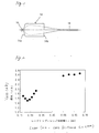
- Fig. 2 shows results of measurement of coupling loss (dB) versus the laser chip to lens distance L 1 in the case where the same lens as described above is used.
- the laser chip to lens distance L 1 is preferably selected to be not larger than 0.3 mm and more preferably in a range of from about 0.20 mm to about 0.25 mm.
- the laser chip to lens distance L 1 is in a range of from 0.2 mm to 0.25 mm, coupling loss is minimized.
- alignment in the axial direction ( z direction) need not be performed because coupling loss would little change even if the distance L 1 changed by the order of tens of microns.
- the light source-optical fiber coupler may be provided as a module structure in which alignment can be made in the axial direction ( z direction) if coupling loss is selected to be as low as possible.
- Fig. 3 shows a specific example of the light source-optical fiber coupler.
- the light source-optical fiber coupler has a semiconductor laser 20, a gradient index rod lens 22, and a housing 30 for retaining the semiconductor laser 20 and the gradient index rod lens 22 and retaining a ferrule of an optical plug (not shown) which is a coupling partner to be fitted to the housing 30.
- the light source-optical fiber coupler has a receptacle type structure in which the semiconductor laser 20 and the single mode optical fiber retained by the ferrule are optically coupled to each other by the gradient index rod lens 22 when connection between the single mode optical fiber and the ferrule is performed in the optical plug.
- the semiconductor laser 10 has a structure in which neither cover glass nor cap is provided.
- a laser chip (device body) 20a is mounted on a chip carrier (heat sink) 20b.
- the chip carrier 20b is further mounted on a base portion 20c. Leads 20d pass through the base portion 20c. In this manner, the gradient index rod lens 22 can be disposed extremely near the laser chip 20a which serves as an emission point.
- the housing 30 is an integrally molded article of resin in which a plurality of holes different in internal diameter are formed along the center axis so as to lie in a line to thereby form a through-hole structure.
- the semiconductor laser 20 is retained by one end portion (left end portion in Fig. 3) 30a of the housing 30, the gradient index rod lens 22 is attached to an inner central portion of the housing.
- a receptacle portion 32 is provided in a region of from the central portion of the housing 30 to an opposite end portion (right end portion in Fig. 3) of the housing 30.
- the receptacle portion 32 is a portion having a bore (cavity portion) 34 into which the ferrule of the optical plug as the coupling partner can be just fitted.
- the gradient index rod lens 22 incorporated in the light source-optical fiber coupler has a semiconductor laser side end surface shaped like a convex spherical surface, and an optical fiber side end surface shaped like a flat surface.
- the semiconductor laser side end surface is disposed close to the emission point of the laser chip 20a (for example, with the laser chip to lens distance ranging from about 0.20 mm to about 0.25 mm).
- the periphery of the gradient index rod lens 22 is fixed by an adhesive agent or the like in the condition that the gradient index rod lens 22 is inserted in the through-hole.
- the semiconductor laser 20 is aligned and connected to the housing 30 which incorporates the gradient index rod lens 22 as described above.
- the semiconductor laser 20 is combined with the housing 30 so that the base portion 20c of the semiconductor laser 20 abuts against the end portion 30a of the housing 30 in the condition that the ferrule of the optical plug is attached into the receptacle portion 32 of the housing 30.
- the semiconductor laser 20 is aligned (in planes perpendicular to the optical axis, that is, in x and y directions) while light emitted from the semiconductor laser 20 is monitored through the single mode optical fiber of the optical fiber.
- the periphery of the base portion 20c is fixed by an adhesive agent 36 of resin in the condition that the semiconductor laser 20 is positioned in the aforementioned manner. This is a structure example in which butt joint between the base portion 20c and the end surface 30a is used so that alignment in the direction ( z direction) of the optical axis is omitted.
- Figs. 4 and 5 are explanatory views showing further specific examples of the light source-optical fiber coupler. Because the basic configuration in Figs. 4 and 5 is the same as that in Fig. 2, identical parts are referenced correspondingly for the sake of simplification of description. Each of these examples shows the structure in which alignment in the direction ( z direction) of the optical axis can be made.
- a housing 40 has a separate structure in which a laser holder 42 for retaining the semiconductor laser and a lens holder 44 for retaining the rod lens 22 are provided separately.
- a part (right portion in Fig. 4) of the lens holder 44 serves as a receptacle portion.
- the receptacle portion is a portion having a bore (cavity portion) 34 into which the ferrule of the optical plug as a coupling partner can be just fitted.
- Alignment in the x-y plane is performed by butt joint between an end surface of the laser holder 42 and an end surface of the lens holder 44. Alignment in the z direction is performed by insertion of the semiconductor laser 20 in the laser holder 42.
- the laser holder 42 is brought into contact with an end surface of the lens holder 44 to perform alignment in the x and y directions.
- the base portion 20c of the semiconductor laser 20 is inserted in an inner circumferential step portion of the laser holder 42 and put out and in to thereby perform alignment in the z direction.
- the position of the semiconductor laser 20 is adjusted while light emitted from the semiconductor laser 20 is monitored through the single mode optical fiber of the optical plug.
- fixation between the laser holder and the lens holder, and fixation between the semiconductor laser and the laser holder are performed by means of welding or the like.
- a housing 50 has a separate structure in which a laser holder 52 for retaining the semiconductor laser and a lens holder 54 for retaining the rod lens 22 are provided separately. Also in this example, a part (right portion in Fig. 5) of the lens holder 54 serves as a receptacle portion.
- the receptacle portion is a portion having a bore (cavity portion) 34 into which the ferrule of the optical plug as a coupling partner can be just fitted.
- the laser holder 52 is fitted to the lens holder 54 to thereby perform alignment in the z direction.
- the semiconductor laser 20 is butt-jointed to the laser holder 52 to thereby perform alignment in the x-y plane.
- the cylindrical laser holder 52 is fitted to an outer circumferential step portion of the lens holder 54 to thereby perform alignment in the z direction.
- the base portion 20c of the semiconductor laser 20 is brought into contact with an end surfce of the laser holder 52 to thereby perform alignment in the x and y directions.
- the position of the semiconductor laser 20 is adjusted while light emitted from the semiconductor laser 20 is monitored through the single mode optical fiber of the optical plug.
- fixation between the laser holder and the lens holder, and fixation between the semiconductor laser and the laser holder are performed by an adhesive agent or the like.
- the example shown in Fig. 4 is configured so that the laser chip 20a does not come into contact with the rod lens 22 (the distance between the laser chip 20a and the rod lens 22 should not be smaller than a specific value) even if the base portion 20c of the semiconductor laser 20 is pushed deepest into the laser holder 42 (i.e., even if the distance restriction surface 20cS of the base portion 20c is brought into abutment with the distance restriction surface 42S of the laser holder 42).
- the laser chip 20a does not come into contact with the rod lens 22 (the distance between the laser chip 20a and the rod lens 22 should not be smaller than a specific value) even if the laser holder 52 is pushed deepest into the lens holder 54 (i.e., even if the distance restriction surface 52s of the laser holder 52 is brought into abutment with the distance restriction surface 54S of the lens holder 54). In this manner, failure can be prevented from being caused by careless contact.
- the gradient index rod lens has a light source side end surface shaped like a convex spherical surface, and an optical fiber side end surface shaped like a flat surface.
- the gradient index rod lens is contained in a housing in the condition that a light source and the lens are disposed close to each other. Hence, eclipse of emitted light can be reduced, so that the coupling loss between the light source and an optical fiber can be reduced. Thus, semiconductor laser-single mode optical fiber coupling can be achieved with high efficiency.
- a spherical surface processing method heretofore used can be used.
- a press mold is not required, so that the lens can be mass-produced easily and inexpensively.
Landscapes
- Physics & Mathematics (AREA)
- General Physics & Mathematics (AREA)
- Optics & Photonics (AREA)
- Optical Couplings Of Light Guides (AREA)
- Semiconductor Lasers (AREA)
- Mechanical Coupling Of Light Guides (AREA)
Abstract
Description
| lens | R1 (mm) | R2 (mm) | Z (mm) | NA2 | h4 | h6 | h8 |
| 00 | 0 | 0 | 4.039 | 0.485 | 0.5711 | 1.478 | -13.20 |
| 11 | 0 | -2.0 | 4.018 | 0.526 | 0.6063 | 1.722 | -14.13 |
| 12 | 0 | -1.8 | 4.015 | 0.532 | 0.6113 | 1.760 | -14.20 |
| 13 | 0 | -1.6 | 4.011 | 0.539 | 0.6179 | 1.821 | -14.31 |
| 14 | 0 | -1.4 | 4.007 | 0.549 | 0.6269 | 1.906 | -14.38 |
| 15 | 0 | -1.2 | 4.002 | 0.565 | 0.6401 | 2.035 | -14.27 |
Claims (8)
- A light source-optical fiber coupler comprising:wherein said gradient index rod lens has a light source side end surface shaped like a convex spherical surface, and an optical fiber side end surface shaped like a flat surface; anda light source; anda gradient index rod lens for coupling diffuse luminous flux emitted from said light source to an end surface of an optical fiber;
wherein said gradient index rod lens has a structure in which said gradient index rod lens is retained by a housing in a state that said gradient index rod lens is disposed close to a laser chip of a semiconductor laser used as said light source and in which said optical fiber can be retained by said housing. - A light source-optical fiber coupler according to claim 1, wherein a distance between a surface of said laser chip and an end surface of said gradient index rod lens is not larger than 0.3 mm.
- A light source-optical fiber coupler according to claim 1 or 2, wherein: said housing includes a laser holder for retaining said semiconductor laser, and a lens holder for retaining said gradient index rod lens; and a position of said semiconductor laser and a position of said gradient index rod lens can be adjusted in an axial direction of an optical axis as well as in an in-plane direction perpendicular to said optical axis and are limited by said laser holder so that a distance between said laser chip and said gradient index rod lens is not smaller than a predetermined value when the position of said laser chip and the position of said gradient index rod lens are adjusted in said axial direction.
- A light source-optical fiber coupler comprising:wherein said gradient index rod lens is held by said housing so that a distance between said laser chip of said semiconductor laser and said convex spherical end surface is 0.3 mm or less.a housing;a semiconductor laser held by said housing, said semiconductor laser chip having an exposed laser chip;a gradient index rod lens having a convex spherical end surface and a flat end surface opposite from said convex spherical end surface;
- A light source-optical fiber coupler according to claim 4, further comprising:a receptacle portion, disposed on said housing, for receiving an optical fiber, whereby said coupler constitutes a receptacle type structure.
- A light source-optical fiber coupler according to claim 4, further comprising:an optical fiber held by said housing, whereby said coupler constitutes a pigtail type structure.
- A light source-optical fiber coupler according to claim 4, wherein said semiconductor laser includes a base portion having a first distance restriction surface, and said housing includes a lens holder having a second distance restriction surface confronted with said first distance restriction surface.
- A light source-optical fiber coupler according to claim 4, wherein said housing includes a laser holder having a first distance restriction surface, and a lens holder having a second distance restriction surface confronted with said first distance restriction surface.
Applications Claiming Priority (2)
| Application Number | Priority Date | Filing Date | Title |
|---|---|---|---|
| JP2000376324A JP2002182073A (en) | 2000-12-11 | 2000-12-11 | Light source-optical fiber coupler |
| JP2000376324 | 2000-12-11 |
Publications (2)
| Publication Number | Publication Date |
|---|---|
| EP1213596A2 true EP1213596A2 (en) | 2002-06-12 |
| EP1213596A3 EP1213596A3 (en) | 2005-03-02 |
Family
ID=18845196
Family Applications (1)
| Application Number | Title | Priority Date | Filing Date |
|---|---|---|---|
| EP01129248A Withdrawn EP1213596A3 (en) | 2000-12-11 | 2001-12-11 | Light source-optical fiber coupler |
Country Status (5)
| Country | Link |
|---|---|
| US (1) | US6862384B2 (en) |
| EP (1) | EP1213596A3 (en) |
| JP (1) | JP2002182073A (en) |
| CN (1) | CN1208648C (en) |
| CA (1) | CA2365141A1 (en) |
Cited By (1)
| Publication number | Priority date | Publication date | Assignee | Title |
|---|---|---|---|---|
| WO2012099769A3 (en) * | 2011-01-20 | 2012-11-22 | Corning Incorporated | Receptacle ferrule assemblies with gradient index lenses and fiber optic connectors using same |
Families Citing this family (23)
| Publication number | Priority date | Publication date | Assignee | Title |
|---|---|---|---|---|
| JP2002328259A (en) * | 2001-04-26 | 2002-11-15 | Nippon Sheet Glass Co Ltd | Optical element |
| JP4037346B2 (en) * | 2003-10-08 | 2008-01-23 | 東洋ガラス株式会社 | Optical fiber coupling parts |
| JP2005215231A (en) | 2004-01-29 | 2005-08-11 | Nippon Sheet Glass Co Ltd | Optical component and its manufacturing method |
| AU2005299243A1 (en) * | 2004-10-25 | 2006-05-04 | Rpo Pty Limited | Planar lenses for integrated optics |
| US7149405B2 (en) * | 2004-10-29 | 2006-12-12 | Avago Technologies General Ip (Singapore) Pte. Ltd. | Electro-optical subassemblies and method for assembly thereof |
| US7282701B2 (en) * | 2005-02-28 | 2007-10-16 | Asml Netherlands B.V. | Sensor for use in a lithographic apparatus |
| US7570849B2 (en) * | 2005-06-21 | 2009-08-04 | Hewlett-Packard Development Company, L.P. | Integrated circuit device having optically coupled layers |
| JP2009175426A (en) * | 2008-01-24 | 2009-08-06 | Funai Electric Co Ltd | Image projector and optical axis adjusting method for the projector |
| US8247756B1 (en) * | 2008-06-03 | 2012-08-21 | Wavefront Research, Inc. | Bi-directional data and signal channels in optical interconnects |
| JP2012168240A (en) * | 2011-02-10 | 2012-09-06 | Sumitomo Electric Device Innovations Inc | Optical module |
| CN103608701B (en) * | 2011-06-15 | 2017-03-29 | 康宁股份有限公司 | The grin lenses of Jing laser treatment and the optic interface device and component using it |
| CN102360105A (en) * | 2011-10-28 | 2012-02-22 | 江苏奥雷光电有限公司 | Method for improving coupling stability of optical active device |
| US9001862B2 (en) | 2012-03-09 | 2015-04-07 | Raytheon Company | Miniaturized solid-state lasing device, system and method |
| JP2014225608A (en) * | 2013-05-17 | 2014-12-04 | スタンレー電気株式会社 | Light-emitting device |
| JP5943209B2 (en) * | 2013-09-11 | 2016-06-29 | ウシオ電機株式会社 | Fiber optic equipment |
| TWI510832B (en) * | 2014-09-12 | 2015-12-01 | Applied Optoelectronics Inc | Transmitting optical sub-assembly and manufacture method thereof |
| CN105020648B (en) * | 2015-06-24 | 2017-06-27 | 江苏大学 | An optical fiber transmission lighting device |
| CN108110608B (en) * | 2018-02-06 | 2024-03-19 | 深圳市光脉电子有限公司 | Array type laser |
| CN112764138B (en) * | 2021-02-21 | 2022-04-29 | 淄博丰雁电子元件有限公司 | TO aspheric lens with high coupling efficiency |
| CN115826152B (en) * | 2021-09-16 | 2025-12-19 | 成都英思嘉半导体技术有限公司 | Optical coupling structure, light emission sub-module and optical module |
| CN116027495A (en) * | 2021-10-26 | 2023-04-28 | 山东华光光电子股份有限公司 | Coupler for semiconductor laser and preparation method thereof |
| CN114709710A (en) * | 2022-03-16 | 2022-07-05 | 潍坊华光光电子有限公司 | Semiconductor optical fiber laser |
| CN117582163B (en) * | 2024-01-12 | 2024-04-19 | 武汉迅微光电技术有限公司 | Endoscopic lighting device |
Family Cites Families (10)
| Publication number | Priority date | Publication date | Assignee | Title |
|---|---|---|---|---|
| JPS61107207A (en) * | 1984-10-30 | 1986-05-26 | Nippon Sheet Glass Co Ltd | Optical coupler |
| US4718055A (en) * | 1985-09-17 | 1988-01-05 | Siemens Aktiengesellschaft | Wave-division multiplex component for an optical network comprising monomode transmission fibers |
| US5087109A (en) * | 1986-10-09 | 1992-02-11 | Matsushita Electric Industrial Co., Ltd. | Method for coupling semiconductor laser with optical fiber |
| FR2611388B1 (en) * | 1987-02-26 | 1991-07-05 | Cit Alcatel | ACTIVE OPTICAL MODULE FOR CONNECTOR SOCKET |
| JPH073907B2 (en) * | 1987-07-03 | 1995-01-18 | 株式会社日立製作所 | Dual in-line package type semiconductor laser module |
| JP2645862B2 (en) * | 1988-08-11 | 1997-08-25 | 株式会社日立製作所 | Semiconductor light emitting device and its applied products |
| JP2684219B2 (en) * | 1989-07-05 | 1997-12-03 | 三菱電機株式会社 | Optical semiconductor module |
| JPH0595169A (en) * | 1991-10-02 | 1993-04-16 | Nec Corp | Semiconductor laser device and semiconductor laser module |
| US5351330A (en) * | 1993-04-08 | 1994-09-27 | Uniphase Corporation | Laser diode-lens alignment |
| US6418251B1 (en) * | 2000-10-13 | 2002-07-09 | Bogie Boscha | Laser-diode assembly for generating a frequency-stabilized narrow-bandwidth light and a method of narrowing linewidth of the spectrum |
-
2000
- 2000-12-11 JP JP2000376324A patent/JP2002182073A/en active Pending
-
2001
- 2001-12-10 CA CA002365141A patent/CA2365141A1/en not_active Abandoned
- 2001-12-10 US US10/007,667 patent/US6862384B2/en not_active Expired - Fee Related
- 2001-12-11 CN CN01144124.0A patent/CN1208648C/en not_active Expired - Lifetime
- 2001-12-11 EP EP01129248A patent/EP1213596A3/en not_active Withdrawn
Cited By (1)
| Publication number | Priority date | Publication date | Assignee | Title |
|---|---|---|---|---|
| WO2012099769A3 (en) * | 2011-01-20 | 2012-11-22 | Corning Incorporated | Receptacle ferrule assemblies with gradient index lenses and fiber optic connectors using same |
Also Published As
| Publication number | Publication date |
|---|---|
| CN1359016A (en) | 2002-07-17 |
| US6862384B2 (en) | 2005-03-01 |
| CA2365141A1 (en) | 2002-06-11 |
| US20020159695A1 (en) | 2002-10-31 |
| EP1213596A3 (en) | 2005-03-02 |
| CN1208648C (en) | 2005-06-29 |
| JP2002182073A (en) | 2002-06-26 |
Similar Documents
| Publication | Publication Date | Title |
|---|---|---|
| US6862384B2 (en) | Light source-optical fiber coupler | |
| US6776537B2 (en) | Light source-optical fiber coupler | |
| US6536959B2 (en) | Coupling configuration for connecting an optical fiber to an optoelectronic component | |
| US20040146252A1 (en) | Optical fibre connector | |
| US8337098B2 (en) | Optical connector | |
| US6687434B2 (en) | Optical element having inclined surface | |
| US20090016683A1 (en) | Angled fiber ferrule having off-axis fiber through-hole and method of coupling an optical fiber at an off-axis angle | |
| WO2011145466A1 (en) | Optical collimator and optical connector using same | |
| US7178989B2 (en) | Optical receptacle and optical sub-assembly using the same | |
| JP4306595B2 (en) | Optical module | |
| JP2004354452A (en) | Optical module, its manufacturing method, and holder for optical modules | |
| JP2005070568A (en) | Optical module | |
| JP2654755B2 (en) | Low-reflection optical components with uneven mating connection | |
| US20040247250A1 (en) | Integrated sleeve pluggable package | |
| JP2004133299A (en) | Optical module | |
| JP4525236B2 (en) | Optical receptacle and optical module | |
| JPH02151817A (en) | light emitting element module | |
| JPH02151819A (en) | light emitting element module | |
| CN103630979A (en) | Optical connector and fitted unit | |
| JP2005010211A (en) | Optical coupling member, optical module and manufacturing method thereof | |
| US20070122089A1 (en) | Optical assembly having fiber-abutting block | |
| JP2003139994A (en) | Optical holder assembling method, optical ferrule press-in method, and optical ferrule receptacle | |
| KR20220118906A (en) | Optical coupling structure, optical coupling method, camera module | |
| KR200267972Y1 (en) | Fiber pigtail | |
| JPH11149018A (en) | Receptacle type surface-mount opto-coupler |
Legal Events
| Date | Code | Title | Description |
|---|---|---|---|
| PUAI | Public reference made under article 153(3) epc to a published international application that has entered the european phase |
Free format text: ORIGINAL CODE: 0009012 |
|
| AK | Designated contracting states |
Kind code of ref document: A2 Designated state(s): AT BE CH CY DE DK ES FI FR GB GR IE IT LI LU MC NL PT SE TR |
|
| AX | Request for extension of the european patent |
Free format text: AL;LT;LV;MK;RO;SI |
|
| PUAL | Search report despatched |
Free format text: ORIGINAL CODE: 0009013 |
|
| AK | Designated contracting states |
Kind code of ref document: A3 Designated state(s): AT BE CH CY DE DK ES FI FR GB GR IE IT LI LU MC NL PT SE TR |
|
| AX | Request for extension of the european patent |
Extension state: AL LT LV MK RO SI |
|
| AKX | Designation fees paid | ||
| REG | Reference to a national code |
Ref country code: DE Ref legal event code: 8566 |
|
| STAA | Information on the status of an ep patent application or granted ep patent |
Free format text: STATUS: THE APPLICATION IS DEEMED TO BE WITHDRAWN |
|
| 18D | Application deemed to be withdrawn |
Effective date: 20050903 |