EP1213573A2 - Method of detecting steam expansion vessel leakage - Google Patents
Method of detecting steam expansion vessel leakage Download PDFInfo
- Publication number
- EP1213573A2 EP1213573A2 EP01128337A EP01128337A EP1213573A2 EP 1213573 A2 EP1213573 A2 EP 1213573A2 EP 01128337 A EP01128337 A EP 01128337A EP 01128337 A EP01128337 A EP 01128337A EP 1213573 A2 EP1213573 A2 EP 1213573A2
- Authority
- EP
- European Patent Office
- Prior art keywords
- expansion vessel
- mold
- steam
- curing
- tire
- Prior art date
- Legal status (The legal status is an assumption and is not a legal conclusion. Google has not performed a legal analysis and makes no representation as to the accuracy of the status listed.)
- Withdrawn
Links
Images


Classifications
-
- G—PHYSICS
- G01—MEASURING; TESTING
- G01M—TESTING STATIC OR DYNAMIC BALANCE OF MACHINES OR STRUCTURES; TESTING OF STRUCTURES OR APPARATUS, NOT OTHERWISE PROVIDED FOR
- G01M3/00—Investigating fluid-tightness of structures
- G01M3/02—Investigating fluid-tightness of structures by using fluid or vacuum
- G01M3/04—Investigating fluid-tightness of structures by using fluid or vacuum by detecting the presence of fluid at the leakage point
- G01M3/16—Investigating fluid-tightness of structures by using fluid or vacuum by detecting the presence of fluid at the leakage point using electric detection means
-
- B—PERFORMING OPERATIONS; TRANSPORTING
- B29—WORKING OF PLASTICS; WORKING OF SUBSTANCES IN A PLASTIC STATE IN GENERAL
- B29D—PRODUCING PARTICULAR ARTICLES FROM PLASTICS OR FROM SUBSTANCES IN A PLASTIC STATE
- B29D30/00—Producing pneumatic or solid tyres or parts thereof
- B29D30/06—Pneumatic tyres or parts thereof (e.g. produced by casting, moulding, compression moulding, injection moulding, centrifugal casting)
- B29D30/0601—Vulcanising tyres; Vulcanising presses for tyres
- B29D30/0662—Accessories, details or auxiliary operations
-
- G—PHYSICS
- G01—MEASURING; TESTING
- G01M—TESTING STATIC OR DYNAMIC BALANCE OF MACHINES OR STRUCTURES; TESTING OF STRUCTURES OR APPARATUS, NOT OTHERWISE PROVIDED FOR
- G01M3/00—Investigating fluid-tightness of structures
- G01M3/02—Investigating fluid-tightness of structures by using fluid or vacuum
- G01M3/04—Investigating fluid-tightness of structures by using fluid or vacuum by detecting the presence of fluid at the leakage point
- G01M3/20—Investigating fluid-tightness of structures by using fluid or vacuum by detecting the presence of fluid at the leakage point using special tracer materials, e.g. dye, fluorescent material, radioactive material
-
- B—PERFORMING OPERATIONS; TRANSPORTING
- B29—WORKING OF PLASTICS; WORKING OF SUBSTANCES IN A PLASTIC STATE IN GENERAL
- B29D—PRODUCING PARTICULAR ARTICLES FROM PLASTICS OR FROM SUBSTANCES IN A PLASTIC STATE
- B29D30/00—Producing pneumatic or solid tyres or parts thereof
- B29D30/06—Pneumatic tyres or parts thereof (e.g. produced by casting, moulding, compression moulding, injection moulding, centrifugal casting)
- B29D30/0601—Vulcanising tyres; Vulcanising presses for tyres
- B29D30/0654—Flexible cores therefor, e.g. bladders, bags, membranes, diaphragms
- B29D2030/0659—Details or accessories for the flexible cores not otherwise provided for
Definitions
- This invention relates to a method for inspecting for evidence of leakage of a steam expansion vessel, and more particularly, to a method for inspecting for evidence of a pinhole leak in a steam expansion vessel.
- Steam expansion vessels may be used in industry to activate equipment, and may have application for a variety of purposes.
- expansion vessel also known as a curing bladder.
- a fluid heat source such as steam.
- the steam causes the expansion vessel to expand, pushing the product tightly against the mold. Further, the heat from the steam helps to at least partially cure the molded product.
- pinhole leaks in expansion vessels on curing devices are one of the industry's largest causes of tire scrap. Pinhole leaks in expansion vessels cost tire manufacturers millions of dollars per year.
- a pinhole leak allows high temperature steam to contact the innerliner of the tire. One possible result of this contact is an undercured area in the innerliner. Another possible result is the permeation of steam into the ply area of the tire, causing a blister that can result in the separation of the plies.
- the first inspection of a tire for the effects of pinhole leaks occurs in the final finish area of the tire plant, minutes after the tire leaves the curing device. If a tire in final finish is found to be defective as a result of a pinhole leak, then up to ten additional tires may have been cured with the same defective expansion vessel prior to discovery of the problem. Generally, all of these tires must be scrapped.
- Cole et al. in US-A- 3,942,922 teach an apparatus for curing a tire having an internal cavity, using steam as a heat and fluid pressure media.
- the time rate of pressure loss in the cavity is determined in each tire curing cycle by closing the cavity to form a completely closed chamber for a test time less than the normal cure time for a tire.
- Pressure loss during the test time is monitored and if determined to be greater than normal, a warning device is actuated and means for loading the next tire into the mold is rendered inactive.
- Garrison in US-A- 4,188,818 teaches a self-contained device for selectively discharging a pressurized gas within a hermetically sealed vessel to enable leak testing of the vessel.
- a linear actuator is used to open a small, high pressure cylinder that is charged with a detector gas.
- the mechanism is mounted on the interior of a lid that is sealed onto the vessel which is to be tested.
- Curing device manufacturers have attempted to limit scrap products caused by pinhole leaks in expansion vessels by incorporating a monitoring system into the curing device. Before a product to be cured is placed into the curing device, the expansion vessel of the curing device is pressurized. The pressurized expansion vessel is isolated by closing the valves in the supply and discharge lines. The monitoring system monitors the pressure in the expansion vessel to determine if a leak is present.
- US-A- 5,417,900 entitled “Vacuum Leak Detector for a Tire Curing Press” discloses a device and a method for detecting a leak in an inflatable elastomeric bladder of a curing press.
- the spent curing fluid is pumped through an exhaust line in which a venturi ejector is located.
- the venturi ejector causes a vacuum to be created as the fluid is being removed.
- a vacuum sensor monitors this vacuum. If a predetermined vacuum strength is not reached in a predetermined time, a leak is assumed to exist.
- detection methods that were tried included sensing the mass flow of nitrogen from the mold; the addition of dye to cure steam and the use of a UV sensor or a color sensor to detect the escape of the dye; the use of tracer gases inserted into a bladder, and the use of gas sensors to detect the tracer gases; the use of infrared thermal sensors; and testing for relative humidity around the mold.
- a method for detecting leaks in a steam activated expansion vessel is used in industrial equipment, and comprises the steps of creating or selecting a path in industrial equipment through which steam would travel if escaping from a steam activated expansion vessel, and placing a humidity sensor in the path.
- the method of detecting leaks comprises the further step of selecting a humidity sensor that has the ability to detect moisture at 25°C to 200°C, and comprises the step of using data from each activation cycle to establish an average or baseline for humidity of a plurality of activation cycles, and comprises the further step of providing computer control for the industrial equipment, such that when a leak is detected an alarm is sounded and the industrial equipment is automatically shut down.
- a further step is provided of placing a filter in the path between the activated expansion vessel and the sensor, the filter being pervious to water vapor.
- the industrial equipment is a curing mold for a pneumatic tire
- the path includes a bolster screw in an area of the mold in the proximity of a bead area of a tire which is being cured in the mold
- the method comprises the further step of placing the humidity sensor in the bolster screw.
- the curing bladder is substantially centered on the tire being cured, and the bolster screw is in the proximity of a curing bladder center post.
- a conduit can be run from the bolster screw to a position remote from the mold, and the humidity sensor can be placed at the end of the conduit.
- the mold in the illustrated embodiment is a two piece mold, and the method may comprise the further step of placing the sensor in or around an upper portion of the mold.
- An apparatus for curing an article comprises a shaping means for shaping the article during curing, an expansion vessel within the shaping means, the expansion vessel having the capacity to withstand elevated temperatures and high pressures.
- the expansion vessel is inflated with steam and used to push the article into the shaping means, and an absolute humidity sensor is located in the proximity of the expansion vessel and the shaping means, in a path selected to detect leaking steam from the expansion vessel.
- the apparatus for curing an article comprises a curing mold for a pneumatic tire, and an absolute humidity sensor which has the ability to detect moisture at 25°C to 200°C.
- the apparatus comprises a two-piece tire mold.
- the apparatus further comprises a magnet attached to the curing mold, the absolute humidity sensor being attached to the magnet, whereby the absolute humidity sensor is held in place by the magnet.
- Bead means that part of the tire comprising an annular tensile member wrapped by ply cords and shaped, with or without other reinforcement elements such as flippers, chippers, apexes, toe guards, and chafers, to fit a design rim.
- the beads are associated with holding the tire to the wheel rim.
- “Curing” means the process of heating or otherwise treating a rubber or plastic compound to convert it from a thermoplastic or fluid material into a solid, relatively heat-resistant state by causing cross-linking of the compound.
- “Elastomer” means a resilient material capable of recovering size and shape after deformation.
- “Elastomeric article” is an article that is at least partially made from an elastomer.
- Innerliner means the layer or layers of elastomer or other material that form the inside surface of a tubeless tire and that contain the inflating fluid within the tire.
- Pneumatic tire means a laminated mechanical device of generally toroidal shape, usually an open torus, having beads and a tread and made of rubber, chemicals, fabric and steel or other materials. When mounted on the wheel of a motor vehicle, the tire, through its tread, provides traction and contains the fluid that sustains the vehicle load.
- Ring and radially are used to mean directions toward or away from the axis of rotation of the tire.
- the present invention will be described as it relates to tire curing equipment. Those skilled in the art will recognize that the invention may be used in other types of curing equipment using a steam expansion vessel, and other types of equipment where a steam expansion vessel can be used.
- an absolute humidity sensor which is used in industry in food processing, autoclaves, steam injection ovens, industrial dryers, clothing dryers, catalyst production, and desiccant heat recovery.
- the sensor used in the illustrated embodiment was provided by Ohmic Instruments Company, Easton, Maryland.
- the ABS-300 sensor has two matched thermistor elements, one being hermetically glass encapsulated in dry nitrogen, and the other exposed to the environment. Air containing water vapor exhibits a thermal conductivity higher than dry nitrogen, and the difference in heat dissipation between the two thermistors creates a temperature differential that is exhibited as an electrical potential difference.
- the sensor has been found to be particularly suitable for measuring absolute humidity at 100°C to 200°C, covering the temperature range used in curing tires, and can be used at 25°C to 200°C.
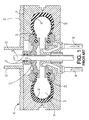
- Fig. 1 illustrates an elastomeric article, in this instance a tire 10, in a prior art curing device 12.
- the curing device 12 has an expansion vessel 14 that inflates when a pressurized fluid is introduced into its interior.
- Fig. 1 shows the expansion vessel in its inflated form, confined in a tire mold 16.
- the inflated expansion vessel 14 forces the elastomeric article tightly against mold 16.
- the pressurized expansion vessel 14 holds the elastomeric article against the mold 16
- the elastomeric article is shaped by the mold and is heated to cause curing.
- the heat may be introduced via the mold 16 or via the pressurized fluid.
- steam is used as both a pressurized fluid and a heat source for at least a portion of the cure time.
- the mold 16 illustrated in Fig. 1 is a two piece mold that separates for the removal of a cured elastomeric article, and insertion of an uncured elastomeric article.
- the pressurized fluid is introduced into the expansion vessel 14 through an inlet channel 18, and exits through an exit channel 20.
- the inlet channel 18 and the exit channel 20 contain valves which work together to regulate the pressure within the expansion vessel 14.
- an uncured tire 10 is placed into a curing device 12 having an expansion vessel 14.
- the uninflated expansion vessel 14 is located radially inwardly of the beads 22 of the tire 10.
- steam is introduced into the expansion vessel 14 and the expansion vessel 14 inflates.
- the expansion vessel 14 will occupy the entire cavity 24 and contact the surface within the cavity 24, pushing the tire 10 against the mold 16.
- the surface within the cavity 24 that is contacted by the expansion vessel 14 is the innerliner of the tire 10.
- the pressurized fluid is contained within the expansion vessel 14 for a predetermined period of time so that the tire 10 may at least partially cure.
- the heat source is removed prior to deflating the expansion vessel 14.
- the steam which acts as the heat source and the pressurized fluid, is slowly released out of the expansion vessel 14 and is replaced by another pressurized fluid, such as nitrogen.
- another pressurized fluid such as nitrogen.
- the pressurized fluid is released from the expansion vessel 14 into the exit channel 20.
- the expansion vessel 14 is deflated and is withdrawn from the cavity 24.
- the mold 16 is opened and the at least partially cured tire 10 is removed from the curing device.
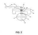
- an absolute humidity sensor 28 is placed in a bolster screw 33 of a prior art curing device 12, in the illustrated embodiment a two-piece mold, near the center post 25 which raises and lowers expansion vessel 14 when the mold 16 is used to cure a tire.
- Center post 25 passes through the middle of expansion vessel 14, which, in the illustrated embodiment, is an elastomer/fabric composite bag.
- the top, open end of the composite bag is gathered by top ring 27, which fits over center post 25.
- the mold 16 operates by inserting a tire, which is to be cured into the mold when the expansion vessel 14 is deflated, and the center post 25 is retracted toward the lower portion of the mold.
- the upper portion 38 of the mold is pressed down over the lower mold portion 23, and the mold is activated by inflating the expansion vessel 14 with steam, and pushing center post 25 toward bolster screw 33.
- O-rings 26, located in top ring 27, seal the expansion vessel 14 against center post 25 to prevent the escape of steam at center post 25.
- Platen 40 is used to apply pressure to the top of the mold, to hold the two mold portions together while the tire is subjected to high pressure, which pushes the tire into the mold, creating a molded pattern on the cured product.
- the center post retracts and extends the top portion of the curing bladder, i.e. the portion of the curing bladder in the top half of the mold, a substantial distance as compared to the movement of the curing bladder in the bottom half of the mold, each time a tire is cured. It is speculated that it is because of the substantial amount of flexing of the top portion of the bladder, as compared to the bottom portion of the bladder, that most defects developed from the use of a curing bladder are found to appear in the top portion of the bladder. Also, hot air and steam tend to rise, and accordingly, it is preferred to locate the absolute humidity sensor in the top half of the mold.
- a curing bladder in operation, contains high pressure steam, and a steam leak at high pressure will force steam into many paths around the curing bladder, and suitable paths for placement of a sensor may be found in the lower half of the mold.
- the inventors have also carried out trials using integrated segmented tire curing molds with disappointing results.
- the inventors speculate that there are too many restrictions in the potential paths for steam in the more complicated integrated segmented molds, and that the steam escaping from punctured curing bladders in a integrated segmented curing mold is not able to find its way to a similarly placed absolute humidity sensor. It is the inventors' belief, however, that knowledge of the nature of the path in the two piece mold can be applied to design a path for the integrated segmented curing mold, and the integrated segmented mold can be modified to provide a path for steam escaping from leaking curing bladders.
- sensor 28 is located in bolster screw 33. This location was chosen since it is proximal to the bead area of a tire, which is being cured. There is a natural path in the mold from the bead area of the tire to bolster screw 33 when the mold is closing or being opened. Thus, when there is a hole in expansion vessel 14, steam that escapes from expansion vessel 14 will make its way along the path in the mold toward bolster screw 33, and will pass by sensor 28.
- Bolster screw 33 is used, as its main function, to adjust the height of the mold press for curing different sized tires.
- the inventors theorized that the tire 10 would act as a barrier against any steam that leaks from expansion vessel 14 preventing its dissipation in the mold, and forcing the steam to follow a path out of the tire cavity 24 toward bead 15.
- Bead 15 is adjacent to post 25 and in the proximity of bolster screw 33, and bolster screw 33 is hollow and open to the atmosphere, providing a natural escape path for the steam.
- the steam pressure inside the curing bladder may be 200 to 300 psig (pounds per square inch gauge) or 1,475 to 2,165 MPa, most bladder defects appear as pin-hole sized cracks or holes, and the total steam lost in a curing cycle may be only 5 cc (cubic centimeters) to 10 cc.
- Bolster screw 33 in effect, acts like a chimney for the venting of expanding and cooling water vapor.
- apparatus using a steam expansion vessel can be modified to create a path in the apparatus for steam escaping from the expansion vessel.
- the absolute humidity sensor can then be placed in the path to detect escaping steam.
- a barrier such as a rubber bladder, can be included in the mold to prevent dissipation of escaping steam, a hole can be drilled in the mold in a location defined by an edge or terminal point of the barrier, and an absolute humidity sensor can be placed in the hole, where it is expected that a concentrated flow of water vapor would be present when there is a leak in the expansion vessel.
- a conduit is used to extend the path from the bolster screw to a point away from the mold, water vapor escaping through the mold can be cooled sufficiently, e.g., to about 25°C, such that a relative humidity sensor can be used to detect the escaping water vapor as well as an absolute humidity sensor.
- a relative humidity sensor could not be used, with proper modifications of the path, it is believed that such a sensor will work.
- Sensor 28 is connected by cable 32 to a data capture display 34 and transmitter 36, which are used to save and collate the data from the sensor and to transmit the data to the user.
- a relative humidity sensor do not work in the invention, because the dew point of escaping steam is so high that data does not register on a relative humidity sensor. Since the temperatures used for curing tires are normally in the range of 140°C to 180°C, in order to test for leaks in a curing bladder by measuring steam loss, it was necessary to find a sensor that is capable of detecting water vapor at 100°C to 200°C, and not be destroyed by the high temperatures involved.
- the sensor used in the illustrated embodiment was provided by Ohmic Instruments Company, Easton, Maryland.
- the ABS-300 sensor has two matched thermistor elements, one being hermetically glass encapsulated in dry nitrogen, and the other exposed to the environment. Air containing water vapor exhibits a thermal conductivity higher than dry nitrogen, and the difference in heat dissipation between the two thermistors creates a temperature differential that is exhibited as an electrical potential difference.
- the absolute humidity sensor 28, as shown in Fig. 2 may be interconnected with the curing device 12, shown in Fig. 1, so that the curing device 12 can be stopped at the completion of a cycle in which escaped steam is discovered. Thus, if it is found that there is a greater amount of water vapor in the atmosphere of bolster screw 33 than is ordinary, the curing device 12 will be stopped.
- the apparatus used to stop the curing mold may be similar to that disclosed in US-A- 3,942,922.
- a filter 35 may be placed in bolster screw 33 to separate escaping water vapor from gases, which may harm sensor 28.
- Filter 35 has a porosity of 2 to 12 microns, preferably about 6 microns, and in the illustrated embodiment is made of fiberglass.
- Teflon® filters can be used in practicing the invention.
- sensor 28 may be made of materials that may be inert to tire off-gases and other chemicals released in the mold, in which case a filter may not be necessary.
- Table 1 and Table 2 in the examples show experimental data collected by following the method of the invention.
- pinhole leaks were deliberately created with 0.64 and 1.3 mm hypodermic needles near the mid-height of the expansion vessel 14.
- the elastomeric article was a P185/65R14 tire.
- the sensor shows a significant change in response over background (normal cure) when a 0.64mm hypodermic needle puncture is made in expansion vessel 14.
- the detection of such a leak was found to correlate with liner defects in cured tires. In this trial, leaks were detected prior to forming a scrap tire, thereby serving as an early detection system for such defects.
- This invention allows for detection of a defect in an expansion vessel during each cycle of the curing device.
- the invention will limit the number of scrap products caused by a pinhole leak to one molded product per defective expansion vessel, and will allow each expansion vessel to be used until a defect occurs.
- this invention will reduce the number of scrap products and the costs associated with changing expansion vessels prior to the end of their effective life.
- an absolute humidity sensor from Ohmic Instruments Company designated ABS-300
- ABS-300 an absolute humidity sensor from Ohmic Instruments Company, designated ABS-300
- Single sensors were mounted on the left cavity and the right cavity in a curing mold where both curing bladders had undergone 472 cures.
- the sensor was screwed to a one-half inch (1,27 cm) magnet 30 (Fig. 2), slid inside the bolster adjusting screw, and attached to the inside wall of the adjusting screw approximately six inches (15,24 cm) above the top ring of the curing bladder (Fig. 2).
- the cable was routed out the top of the adjusting screw hole and across to the side of the press frame, where the transmitter was mounted.
- the same configuration was used for the adjacent mold cavity (each mold has two mold cavities, in this mold designated as No. 2009 and No. 2010), and the cables for the two sensors were bundled at the same spot on the press frame.
- the transmitter signals were sent to a Gould WindoGraf data capture and display unit.
- the unit and the power supply were connected to a power receptacle on an adjacent press.
- the o-rings 26 are located in the top ring of the expansion vessel 14, said ring being fixed around post 25, and the o-rings are designed to prevent leakage of steam from the bladder around post 25.
- the same hypodermic needle was used to punch a hole in the bladder in press cavity 2009. Apparently the hole re-sealed spontaneously since no voltage change was seen and no leak was detected, and the tire cured in the mold was not damaged. During the same cure cycle, a voltage was detected for the curing bladder in cavity 2010, which had been previously perforated with a needle, but the tire cured in 2010 only showed borderline defects. For the next cure, a larger 1.3 mm needle was used to poke a second hole in the bladder in press cavity 2009. The first hole made in the 2009 bladder was three inches below the centerline. The second, larger pin hole pinhole made in 2009 was made in the same spot as the initial puncture.
- the voltage response 46 of the sensor in a curing mold where the curing bladder has integrity, and there is no steam loss, is actually about 0.6 volts, whereas the voltage differential 50 for a bladder which has a 0.6 mm hole varies from about one volt when the press is first closed to about 3 volts when the steam is injected into the bladder (it is noted that the time coordinate is not to scale).
- the voltage 48 registered by the sensor gradually tapers off to about 1 volt just before the press is opened. This information can be used in an algorithm which is used to automatically stop the curing sequence when a bladder leak is detected.
- the first experiment resulted in a bladder leak being detected two tires prior to forming a defective tire. It is realized, however, that needle punctures may be cleaner and less likely to produce tire defects than normal production defects.
- the bladder has a smooth area 42 (Fig. 2) around the centerline that seals tightly to the tire liner, which may prevent the steam from finding the path upon inflation, but then is released upon deflation of the bladder.
Landscapes
- Physics & Mathematics (AREA)
- General Physics & Mathematics (AREA)
- Engineering & Computer Science (AREA)
- Mechanical Engineering (AREA)
- Heating, Cooling, Or Curing Plastics Or The Like In General (AREA)
- Moulds For Moulding Plastics Or The Like (AREA)
- Examining Or Testing Airtightness (AREA)
Abstract
Description
| Test results from absolute humidity sensor trail - first day 9/19/00 | |||||||
| Cure run | Press cavity | Hole? | Hole size, mm | Hole location | Voltage change, inflation | Voltage change, deflation | Leaker defect? |
| 1 | 2009 | N | - | - | 6.2 | 0 | N |
| : | 2010 | N | - | - | 4.4 | 0 | |
| 2 | 2009 | N | - | - | 7.1 | 0 | N |
| 2010 | N | - | - | 4.8 | 0 | N | |
| Top o-rings changed on both 2009 and 2010 | |||||||
| 3 | 2009 | N | - | - | 0 | 0 | N |
| 2010 | N | - | - | 0 | 0 | N | |
| 4 | 2009 | N | - | - | 0 | 0 | N |
| 2010 | N | - | - | 0 | 0 | | |
| 5 | 2009 | N | - | - | 0 | 0 | N |
| 2010 | N | - | - | 0 | 0 | N | |
| Poked hole on left side = 2010 | |||||||
| 6 | 2009 | N | - | - | 0 | 0 | N |
| 2010 | Y | 0.64 | Upper | 3.5 | 0 | N | |
| 7 | 2009 | N | - | - | 0 | 0 | N |
| 2010 | Y | 0.64 | Upper | 3.5 | 0 | N | |
| Poked hole on rig ht side = 2009 | |||||||
| 8 | 2009 | Y | 0.64 | Lower | 0 | 0 | N |
| 2010 | Y | 0.64 | Upper | 3.1 | 0 | Y | |
| Poked larger hole on right side = 2009 | |||||||
| 9 | 2009 | Y | 1.3 | Lower | 0 | 3.4 | Y |
| 2010 | Y | 0.64 | Upper | 3.1 | 0 | Y |
| Test results from absolute humidity sensor trial - second day 9/20/00 | ||||||||
| Cure run | Press cavity | Hole? | Hole size, mm | Hole Locatio n | Voltage Change, Inflate | Voltage Change, Deflate | Leaker Defect? | |
| 1 | 2009 | N | - | - | 0 | 0 | N | |
| 2010 | N | - | - | 0 | 0 | | ||
| 2 | 2009 | N | - | - | 0 | 0 | N | |
| 2010 | N | - | - | 0 | 0 | | ||
| 3 | 2009 | N | - | - | 0 | 0 | N | |
| 2010 | N | - | - | 0 | 0 | N | ||
| Swabbed tires with silicone release agent | ||||||||
| 4 | 2009 | N | - | - | 0 | 0 | N | |
| 2010 | N | - | - | 0 | 0 | | ||
| 5 | 2009 | N | - | - | 0 | 0 | N | |
| 2010 | N | - | - | 0 | 0 | N | ||
| 6 | 2010 | N | - | - | 0 | 0 | N | |
| 2009 | N | - | - | 0 | 0 | N | ||
| Poked hole on left side = 2010 | ||||||||
| 7 | 2009 | N | - | - | 0 | 0 | N | |
| 2010 | Y | 1.3 | Upper | 0 | 6.5 | Y |
Claims (8)
- A method for detecting leaks in a steam activated expansion vessel (14) used in industrial equipment comprising the steps of:(a) creating or selecting a path in industrial equipment through which steam would travel if escaping from a steam activated expansion vessel; and(b) placing a humidity sensor (28) in said path.
- The method of claim 1 comprising the further step of selecting a humidity sensor (28) that has the ability to detect moisture at 25°C to 200°C.
- The method of claim 1 comprising the step of selecting an absolute humidity sensor (28) that has the ability to detect moisture at 25°C to 200°C.
- The method of claim 1 comprising the step of placing a filter (35) in said path between said steam activated expansion vessel (14) and said sensor (28), said filter being pervious to water vapor.
- The method of claim 3 wherein the industrial equipment is a curing mold (16) for a pneumatic tire (10) and the path is a bolster screw (33) in an area of the mold in the proximity of a bead area (22) of a tire which is being cured in the mold.
- An apparatus for curing an article, said apparatus comprising:(a) a shaping means for shaping the article during curing;(b) an expansion vessel (14) within said shaping means, said expansion vessel having the capacity to withstand elevated temperatures and high pressures, said expansion vessel being inflated with steam and being used to push the article into said shaping means; and(c) an absolute humidity sensor (28) located in the proximity of said expansion vessel (14) and said shaping means (16) for detecting escaping steam from said expansion vessel.
- The apparatus of claim 6 wherein the shaping means is a mold (16) and wherein a bolster screw (33) is in proximity to a bead (22) of a tire (10) which is cured in said mold, and wherein said absolute humidity sensor (28) is placed in said bolster screw (33) and a filter (35) placed between said expansion vessel and said absolute humidity sensor, said filter having the capacity to permit passage of water vapor while trapping most other gases.
- The apparatus of claim 6 comprising a barrier surrounding said expansion vessel, said barrier providing at least a portion of a path to said absolute humidity sensor (28).
Applications Claiming Priority (2)
| Application Number | Priority Date | Filing Date | Title |
|---|---|---|---|
| US732689 | 1985-05-10 | ||
| US09/732,689 US6401524B1 (en) | 2000-12-08 | 2000-12-08 | Method of detecting steam expansion vessel leakage |
Publications (2)
| Publication Number | Publication Date |
|---|---|
| EP1213573A2 true EP1213573A2 (en) | 2002-06-12 |
| EP1213573A3 EP1213573A3 (en) | 2004-03-03 |
Family
ID=24944597
Family Applications (1)
| Application Number | Title | Priority Date | Filing Date |
|---|---|---|---|
| EP01128337A Withdrawn EP1213573A3 (en) | 2000-12-08 | 2001-11-29 | Method of detecting steam expansion vessel leakage |
Country Status (5)
| Country | Link |
|---|---|
| US (1) | US6401524B1 (en) |
| EP (1) | EP1213573A3 (en) |
| JP (1) | JP4171209B2 (en) |
| BR (1) | BR0105897A (en) |
| MX (1) | MXPA01012161A (en) |
Cited By (4)
| Publication number | Priority date | Publication date | Assignee | Title |
|---|---|---|---|---|
| EP1627717A1 (en) * | 2004-08-18 | 2006-02-22 | The Goodyear Tire & Rubber Company | Method and apparatus to detect leaks in expansion vessel |
| CN103128891A (en) * | 2011-11-29 | 2013-06-05 | 住友橡胶工业株式会社 | Vulcanization forming method of pneumatic tyres for cars |
| WO2018064264A1 (en) * | 2016-09-30 | 2018-04-05 | Compagnie Generale Des Etablissements Michelin | Method of detecting tire mold bladder leakage by smell |
| WO2024132762A1 (en) | 2022-12-22 | 2024-06-27 | Compagnie Generale Des Etablissements Michelin | Leak detection method with time delay for detecting a leak that affects a tyre curing membrane or the inflation circuit thereof |
Families Citing this family (26)
| Publication number | Priority date | Publication date | Assignee | Title |
|---|---|---|---|---|
| US6553809B1 (en) * | 2001-11-01 | 2003-04-29 | Plastic Technologies, Inc. | Method and apparatus for detecting holes in plastic containers |
| US6718818B2 (en) * | 2002-07-19 | 2004-04-13 | The Goodyear Tire & Rubber Company | Method of sensing air leaks in tires and tire testing machines |
| US8114335B2 (en) * | 2002-12-30 | 2012-02-14 | The Goodyear Tire & Rubber Company | Partial depth-wise cure of a tire inner liner |
| US20050026763A1 (en) * | 2003-07-30 | 2005-02-03 | Brock Lape | Helium tracer gas bags and related method |
| US8015726B2 (en) * | 2005-06-23 | 2011-09-13 | Whirlpool Corporation | Automatic clothes dryer |
| DE102006020003A1 (en) * | 2006-04-26 | 2007-10-31 | Herbert Kannegiesser Gmbh | Method for recovering the heat energy emitted by laundry machines |
| US20080035647A1 (en) * | 2006-08-08 | 2008-02-14 | James Fuller | Expansion tank with a predictive sensor |
| US8062575B2 (en) * | 2006-10-05 | 2011-11-22 | Tom Raben | Tire testing apparatus and method |
| DE102007037605A1 (en) | 2007-08-07 | 2009-02-12 | Mars Incorporated | Method and device for drying a material |
| WO2009117399A2 (en) * | 2008-03-17 | 2009-09-24 | Plastic Technologies, Inc. | Method and apparatus for improved detection of holes in plastic containers |
| US7987697B2 (en) * | 2008-07-14 | 2011-08-02 | Continental Tire North America, Inc. | Curing bladder leak detection system for a tire press |
| JP5153585B2 (en) * | 2008-11-11 | 2013-02-27 | 住友ゴム工業株式会社 | Puncture detection device and puncture detection method for tire vulcanization bladder |
| DE102009015578A1 (en) * | 2009-03-30 | 2010-10-07 | Mars Incorporated | Extrusion and conditioning device |
| US8539818B2 (en) * | 2010-02-01 | 2013-09-24 | The Boeing Company | Methods and systems for evaporative cooling infrared thermographic leak detection |
| US9427506B2 (en) * | 2010-03-31 | 2016-08-30 | Kci Licensing, Inc. | System and method for locating fluid leaks at a drape using sensing techniques |
| JP5612400B2 (en) * | 2010-09-02 | 2014-10-22 | 株式会社ブリヂストン | Replacement time determination method and replacement time determination apparatus for tire vulcanizing bladder |
| JP5706847B2 (en) * | 2012-04-16 | 2015-04-22 | 住友ゴム工業株式会社 | Puncture detection device and puncture detection method for tire vulcanization bladder |
| TW201411108A (en) * | 2012-09-14 | 2014-03-16 | Askey Computer Corp | Testing fixture and testing method |
| KR20180041093A (en) * | 2015-05-18 | 2018-04-23 | 넥세리스, 엘엘씨 | Gas monitoring systems and methods for reactors |
| JP6651125B2 (en) * | 2015-08-21 | 2020-02-19 | 住友ゴム工業株式会社 | How to detect bladder punk |
| US10428965B1 (en) | 2016-04-25 | 2019-10-01 | Durbin Industrial Valve Repair, Inc. | Digital flow control valve for curing press |
| CN106153106B (en) * | 2016-06-23 | 2018-05-18 | 北方工业大学 | A working condition information collection device for a sealed container |
| JP6798190B2 (en) * | 2016-08-19 | 2020-12-09 | 住友ゴム工業株式会社 | Vulcanizer and manufacturing method for pneumatic tires |
| JP7451984B2 (en) * | 2019-12-12 | 2024-03-19 | 住友ゴム工業株式会社 | puncture detection device |
| CN116989943B (en) * | 2023-09-25 | 2023-12-05 | 辽宁北方机械股份有限公司 | Air tightness detection device in use process of air pressure kettle |
| CN117109812B (en) * | 2023-10-23 | 2024-01-16 | 常州乐研分离技术有限公司 | Structure tightness detection equipment for evaporation drying integrated machine |
Family Cites Families (19)
| Publication number | Priority date | Publication date | Assignee | Title |
|---|---|---|---|---|
| US3320969A (en) * | 1962-07-27 | 1967-05-23 | Stone & Webster Eng Corp | Nuclear containment vessels |
| US3444725A (en) * | 1967-04-06 | 1969-05-20 | Stone & Webster Eng Corp | Leak detecting and locating system for nuclear reactor containment vessels |
| US3914983A (en) * | 1972-04-26 | 1975-10-28 | Ulvac Corp | Leak test machine and method of operation |
| US3888111A (en) * | 1973-11-21 | 1975-06-10 | Gen Motors Corp | Sealed beam headlamp unit leak detection system |
| US3942922A (en) * | 1974-04-01 | 1976-03-09 | The Goodyear Tire & Rubber Company | Tire press and mold leakage control |
| US4199975A (en) * | 1976-04-12 | 1980-04-29 | Westinghouse Electric Corp. | Method and apparatus for locating a defective tube of a liquid metal-to-water tube type heat exchanger |
| US4120193A (en) * | 1977-05-12 | 1978-10-17 | Uniroyal, Inc. | Leak-detecting apparatus |
| US4221124A (en) * | 1978-07-27 | 1980-09-09 | Nrm Corporation | Bladder leak and rupture detector |
| US4188818A (en) * | 1978-10-04 | 1980-02-19 | Teledyne McCormick Selph (an operating division of Teledyne Industries, Inc.) | Mechanism for leak testing of hermetically sealed vessels |
| US4226113A (en) * | 1979-04-11 | 1980-10-07 | Electric Power Research Institute, Inc. | Leak detecting arrangement especially suitable for a steam condenser and method |
| US4524607A (en) * | 1982-04-05 | 1985-06-25 | Science Applications International Corporation | System and method for locating leaking tubes |
| GB2246633A (en) * | 1990-07-11 | 1992-02-05 | Brownell Limited | Improvements in or relating to leak location |
| US5168747A (en) * | 1990-11-26 | 1992-12-08 | Westinghouse Electric Corp. | System and method for locating leaks in steam turbine systems |
| JP2825172B2 (en) * | 1992-07-10 | 1998-11-18 | 東京エレクトロン株式会社 | Reduced pressure processing apparatus and reduced pressure processing method |
| US5417900A (en) * | 1993-07-07 | 1995-05-23 | Bridgestone/Firestone, Inc. | Vacuum leak detector for a tire curing press |
| US5663489A (en) * | 1994-11-14 | 1997-09-02 | Betzdearborn Inc. | Methods and apparatus for monitoring water process equipment |
| US5687606A (en) * | 1996-01-04 | 1997-11-18 | Boart Longyear Company | Moisture detector |
| US5767390A (en) * | 1996-06-14 | 1998-06-16 | Environmental Fuel Systems, Inc. | System and method for storage system leak detection |
| FR2761776B1 (en) * | 1997-04-03 | 1999-07-23 | Alsthom Cge Alcatel | GAS LEAK DETECTOR |
-
2000
- 2000-12-08 US US09/732,689 patent/US6401524B1/en not_active Expired - Fee Related
-
2001
- 2001-11-27 MX MXPA01012161A patent/MXPA01012161A/en active IP Right Grant
- 2001-11-29 EP EP01128337A patent/EP1213573A3/en not_active Withdrawn
- 2001-12-04 BR BR0105897-5A patent/BR0105897A/en not_active IP Right Cessation
- 2001-12-10 JP JP2001375548A patent/JP4171209B2/en not_active Expired - Fee Related
Cited By (7)
| Publication number | Priority date | Publication date | Assignee | Title |
|---|---|---|---|---|
| EP1627717A1 (en) * | 2004-08-18 | 2006-02-22 | The Goodyear Tire & Rubber Company | Method and apparatus to detect leaks in expansion vessel |
| CN103128891A (en) * | 2011-11-29 | 2013-06-05 | 住友橡胶工业株式会社 | Vulcanization forming method of pneumatic tyres for cars |
| CN103128891B (en) * | 2011-11-29 | 2016-02-10 | 住友橡胶工业株式会社 | The airtyred sulfuration method for shaping of car |
| WO2018064264A1 (en) * | 2016-09-30 | 2018-04-05 | Compagnie Generale Des Etablissements Michelin | Method of detecting tire mold bladder leakage by smell |
| WO2018063264A1 (en) * | 2016-09-30 | 2018-04-05 | Compagnie Generale Des Etablissements Michelin | Method of detecting tire mold bladder leakage by smell |
| WO2024132762A1 (en) | 2022-12-22 | 2024-06-27 | Compagnie Generale Des Etablissements Michelin | Leak detection method with time delay for detecting a leak that affects a tyre curing membrane or the inflation circuit thereof |
| FR3144283A1 (en) | 2022-12-22 | 2024-06-28 | Compagnie Generale Des Etablissements Michelin | LEAK DETECTION METHOD WITH TIME DELAY FOR DETECTING A LEAK WHICH AFFECTS A BANDAGE COOKING MEMBRANE OR THE INFLATION CIRCUIT OF SAID MEMBRANE |
Also Published As
| Publication number | Publication date |
|---|---|
| BR0105897A (en) | 2002-08-06 |
| EP1213573A3 (en) | 2004-03-03 |
| US6401524B1 (en) | 2002-06-11 |
| JP4171209B2 (en) | 2008-10-22 |
| MXPA01012161A (en) | 2002-07-09 |
| JP2002210742A (en) | 2002-07-30 |
Similar Documents
| Publication | Publication Date | Title |
|---|---|---|
| US6401524B1 (en) | Method of detecting steam expansion vessel leakage | |
| US6330821B1 (en) | Method of detecting expansion vessel leakage | |
| EP1627717A1 (en) | Method and apparatus to detect leaks in expansion vessel | |
| US4754638A (en) | Apparatus and method for leak testing automotive wheel rims | |
| US5850036A (en) | Apparatus for leak testing vehicle wheels | |
| DE69310829D1 (en) | Method and device for checking bag-like objects | |
| US7987697B2 (en) | Curing bladder leak detection system for a tire press | |
| CN109562585B (en) | Method for detecting leaks from tire mold bladders by smell | |
| MY128572A (en) | Method and apparatus for building pneumatic tires in an improved tire mold | |
| IE45076B1 (en) | Method for bonding tread strips to tire bodies | |
| US3029469A (en) | Leak detecting device for tire vulcanization press | |
| US5417900A (en) | Vacuum leak detector for a tire curing press | |
| US4221124A (en) | Bladder leak and rupture detector | |
| US5510718A (en) | Container leak testing | |
| CN109655213A (en) | A kind of gloves gas leak detection device and its working method | |
| CA2151983C (en) | Apparatus and method including porous liner for testing for holes in prophylactic devices | |
| US6164122A (en) | System and method including multiple test chambers for automated testing for holes in prophylactic device | |
| US4203793A (en) | Pressure vessel system for retreading tires | |
| CN216116597U (en) | A broken hourglass check out test set for lamp shade product | |
| JP2001191332A (en) | Puncture detection method for tire vulcanizing bladders | |
| KR100594848B1 (en) | Adjusting device for lowering position of expansion forest of vulcanizer | |
| JPS62109611A (en) | Detector for extraneous movement of vulcanizing bladder | |
| JP2006226877A (en) | Method and device for detecting air leakage in air sac | |
| JP2021030541A (en) | Vulcanizer for pneumatic tire |
Legal Events
| Date | Code | Title | Description |
|---|---|---|---|
| PUAI | Public reference made under article 153(3) epc to a published international application that has entered the european phase |
Free format text: ORIGINAL CODE: 0009012 |
|
| AK | Designated contracting states |
Kind code of ref document: A2 Designated state(s): AT BE CH CY DE DK ES FI FR GB GR IE IT LI LU MC NL PT SE TR |
|
| AX | Request for extension of the european patent |
Free format text: AL;LT;LV;MK;RO;SI |
|
| PUAL | Search report despatched |
Free format text: ORIGINAL CODE: 0009013 |
|
| AK | Designated contracting states |
Kind code of ref document: A3 Designated state(s): AT BE CH CY DE DK ES FI FR GB GR IE IT LI LU MC NL PT SE TR |
|
| AX | Request for extension of the european patent |
Extension state: AL LT LV MK RO SI |
|
| RIC1 | Information provided on ipc code assigned before grant |
Ipc: 7G 01M 3/32 B Ipc: 7G 01M 3/22 A |
|
| 17P | Request for examination filed |
Effective date: 20040903 |
|
| AKX | Designation fees paid |
Designated state(s): DE ES FR GB IT |
|
| STAA | Information on the status of an ep patent application or granted ep patent |
Free format text: STATUS: THE APPLICATION HAS BEEN WITHDRAWN |
|
| 18W | Application withdrawn |
Effective date: 20080811 |