EP1213515A1 - Seal member - Google Patents
Seal member Download PDFInfo
- Publication number
- EP1213515A1 EP1213515A1 EP20010934458 EP01934458A EP1213515A1 EP 1213515 A1 EP1213515 A1 EP 1213515A1 EP 20010934458 EP20010934458 EP 20010934458 EP 01934458 A EP01934458 A EP 01934458A EP 1213515 A1 EP1213515 A1 EP 1213515A1
- Authority
- EP
- European Patent Office
- Prior art keywords
- sealing member
- ring
- barrier film
- rubber
- gas barrier
- Prior art date
- Legal status (The legal status is an assumption and is not a legal conclusion. Google has not performed a legal analysis and makes no representation as to the accuracy of the status listed.)
- Withdrawn
Links
- 238000007789 sealing Methods 0.000 claims abstract description 63
- 239000000463 material Substances 0.000 claims abstract description 56
- 230000004888 barrier function Effects 0.000 claims abstract description 54
- 239000011347 resin Substances 0.000 claims abstract description 15
- 229920005989 resin Polymers 0.000 claims abstract description 15
- 229920005549 butyl rubber Polymers 0.000 claims abstract description 9
- 229920001971 elastomer Polymers 0.000 claims description 36
- CURLTUGMZLYLDI-UHFFFAOYSA-N Carbon dioxide Chemical compound O=C=O CURLTUGMZLYLDI-UHFFFAOYSA-N 0.000 claims description 31
- 239000005060 rubber Substances 0.000 claims description 30
- 229910002092 carbon dioxide Inorganic materials 0.000 claims description 28
- 239000001569 carbon dioxide Substances 0.000 claims description 28
- NLHHRLWOUZZQLW-UHFFFAOYSA-N Acrylonitrile Chemical compound C=CC#N NLHHRLWOUZZQLW-UHFFFAOYSA-N 0.000 claims description 24
- 229920000459 Nitrile rubber Polymers 0.000 claims description 12
- 229920001577 copolymer Polymers 0.000 claims description 12
- 239000000806 elastomer Substances 0.000 claims description 6
- 239000011162 core material Substances 0.000 description 14
- 239000003507 refrigerant Substances 0.000 description 7
- 239000002184 metal Substances 0.000 description 6
- 238000000465 moulding Methods 0.000 description 4
- 230000000694 effects Effects 0.000 description 3
- NBVXSUQYWXRMNV-UHFFFAOYSA-N fluoromethane Chemical compound FC NBVXSUQYWXRMNV-UHFFFAOYSA-N 0.000 description 3
- 229920003051 synthetic elastomer Polymers 0.000 description 3
- 239000005061 synthetic rubber Substances 0.000 description 3
- 238000010276 construction Methods 0.000 description 2
- 230000007246 mechanism Effects 0.000 description 2
- 239000000203 mixture Substances 0.000 description 2
- 239000002904 solvent Substances 0.000 description 2
- 239000004677 Nylon Substances 0.000 description 1
- 229920001328 Polyvinylidene chloride Polymers 0.000 description 1
- XECAHXYUAAWDEL-UHFFFAOYSA-N acrylonitrile butadiene styrene Chemical compound C=CC=C.C=CC#N.C=CC1=CC=CC=C1 XECAHXYUAAWDEL-UHFFFAOYSA-N 0.000 description 1
- 229920000122 acrylonitrile butadiene styrene Polymers 0.000 description 1
- 239000004676 acrylonitrile butadiene styrene Substances 0.000 description 1
- 229920001893 acrylonitrile styrene Polymers 0.000 description 1
- 238000001035 drying Methods 0.000 description 1
- 229920001973 fluoroelastomer Polymers 0.000 description 1
- 239000010687 lubricating oil Substances 0.000 description 1
- 238000004519 manufacturing process Methods 0.000 description 1
- 239000007769 metal material Substances 0.000 description 1
- 230000004048 modification Effects 0.000 description 1
- 238000012986 modification Methods 0.000 description 1
- 229920001778 nylon Polymers 0.000 description 1
- 230000035699 permeability Effects 0.000 description 1
- 239000005033 polyvinylidene chloride Substances 0.000 description 1
- SCUZVMOVTVSBLE-UHFFFAOYSA-N prop-2-enenitrile;styrene Chemical compound C=CC#N.C=CC1=CC=CC=C1 SCUZVMOVTVSBLE-UHFFFAOYSA-N 0.000 description 1
- 230000009467 reduction Effects 0.000 description 1
Images



Classifications
-
- F—MECHANICAL ENGINEERING; LIGHTING; HEATING; WEAPONS; BLASTING
- F16—ENGINEERING ELEMENTS AND UNITS; GENERAL MEASURES FOR PRODUCING AND MAINTAINING EFFECTIVE FUNCTIONING OF MACHINES OR INSTALLATIONS; THERMAL INSULATION IN GENERAL
- F16J—PISTONS; CYLINDERS; SEALINGS
- F16J15/00—Sealings
- F16J15/02—Sealings between relatively-stationary surfaces
- F16J15/021—Sealings between relatively-stationary surfaces with elastic packing
- F16J15/022—Sealings between relatively-stationary surfaces with elastic packing characterised by structure or material
-
- F—MECHANICAL ENGINEERING; LIGHTING; HEATING; WEAPONS; BLASTING
- F16—ENGINEERING ELEMENTS AND UNITS; GENERAL MEASURES FOR PRODUCING AND MAINTAINING EFFECTIVE FUNCTIONING OF MACHINES OR INSTALLATIONS; THERMAL INSULATION IN GENERAL
- F16J—PISTONS; CYLINDERS; SEALINGS
- F16J15/00—Sealings
- F16J15/16—Sealings between relatively-moving surfaces
- F16J15/32—Sealings between relatively-moving surfaces with elastic sealings, e.g. O-rings
-
- F—MECHANICAL ENGINEERING; LIGHTING; HEATING; WEAPONS; BLASTING
- F16—ENGINEERING ELEMENTS AND UNITS; GENERAL MEASURES FOR PRODUCING AND MAINTAINING EFFECTIVE FUNCTIONING OF MACHINES OR INSTALLATIONS; THERMAL INSULATION IN GENERAL
- F16J—PISTONS; CYLINDERS; SEALINGS
- F16J15/00—Sealings
- F16J15/16—Sealings between relatively-moving surfaces
- F16J15/32—Sealings between relatively-moving surfaces with elastic sealings, e.g. O-rings
- F16J15/3204—Sealings between relatively-moving surfaces with elastic sealings, e.g. O-rings with at least one lip
- F16J15/3228—Sealings between relatively-moving surfaces with elastic sealings, e.g. O-rings with at least one lip formed by deforming a flat ring
-
- Y—GENERAL TAGGING OF NEW TECHNOLOGICAL DEVELOPMENTS; GENERAL TAGGING OF CROSS-SECTIONAL TECHNOLOGIES SPANNING OVER SEVERAL SECTIONS OF THE IPC; TECHNICAL SUBJECTS COVERED BY FORMER USPC CROSS-REFERENCE ART COLLECTIONS [XRACs] AND DIGESTS
- Y10—TECHNICAL SUBJECTS COVERED BY FORMER USPC
- Y10T—TECHNICAL SUBJECTS COVERED BY FORMER US CLASSIFICATION
- Y10T428/00—Stock material or miscellaneous articles
- Y10T428/31504—Composite [nonstructural laminate]
- Y10T428/31826—Of natural rubber
- Y10T428/31833—Next to aldehyde or ketone condensation product or addition polymer from unsaturated monomers
- Y10T428/31837—Including polyene monomers
-
- Y—GENERAL TAGGING OF NEW TECHNOLOGICAL DEVELOPMENTS; GENERAL TAGGING OF CROSS-SECTIONAL TECHNOLOGIES SPANNING OVER SEVERAL SECTIONS OF THE IPC; TECHNICAL SUBJECTS COVERED BY FORMER USPC CROSS-REFERENCE ART COLLECTIONS [XRACs] AND DIGESTS
- Y10—TECHNICAL SUBJECTS COVERED BY FORMER USPC
- Y10T—TECHNICAL SUBJECTS COVERED BY FORMER US CLASSIFICATION
- Y10T428/00—Stock material or miscellaneous articles
- Y10T428/31504—Composite [nonstructural laminate]
- Y10T428/31855—Of addition polymer from unsaturated monomers
- Y10T428/31909—Next to second addition polymer from unsaturated monomers
- Y10T428/31913—Monoolefin polymer
- Y10T428/31917—Next to polyene polymer
-
- Y—GENERAL TAGGING OF NEW TECHNOLOGICAL DEVELOPMENTS; GENERAL TAGGING OF CROSS-SECTIONAL TECHNOLOGIES SPANNING OVER SEVERAL SECTIONS OF THE IPC; TECHNICAL SUBJECTS COVERED BY FORMER USPC CROSS-REFERENCE ART COLLECTIONS [XRACs] AND DIGESTS
- Y10—TECHNICAL SUBJECTS COVERED BY FORMER USPC
- Y10T—TECHNICAL SUBJECTS COVERED BY FORMER US CLASSIFICATION
- Y10T428/00—Stock material or miscellaneous articles
- Y10T428/31504—Composite [nonstructural laminate]
- Y10T428/31855—Of addition polymer from unsaturated monomers
- Y10T428/31909—Next to second addition polymer from unsaturated monomers
- Y10T428/31928—Ester, halide or nitrile of addition polymer
Definitions
- the present invention relates to a sealing member for sealing housing members jointed to one another or sealing a rotating shaft supported by the housing.
- a general compressor used in an air conditioner comprises a housing comprised of a plurality of housing members.
- the housing members are jointed to the adjacent ones through bolts.
- a sealing member for preventing gas leakage is provided between the adjacent housing members.
- Japanese Unexamined Patent Publication Nos. Hei 8-261150 and Hei 9-42156 disclose a multiple sealing mechanism in which a plurality of sealing members made of a rubber are provided between adjacent housing members.
- CO 2 carbon dioxide
- a rubber is permeable to CO 2 .
- the pressure in the air conditioner is considerably high, as compared to that in the case where a Fluorocarbon is used.
- the conventional sealing member made of a rubber cannot satisfactorily prevent CO 2 from leaking.
- Japanese Unexamined Utility Model Publication No. Hei 5-57520 discloses a lip-shaped seal for sealing rotating shaft 35 supported by a compressor housing.
- Character A indicates a closed space defined in the compressor housing.
- the lip-shaped seal comprises a lip member 32 provided in a casing 31 made of a metal.
- the lip member 32 is supported by a supporting ring 33 made of a resin having a higher stiffness than an elastomer.
- the lip member 32 comprises a main body 32a made of a resin, which has a higher stiffness than an elastomer and which is less permeable to Fluorocarbon, and a synthetic rubber film (fluororubber film) 34 coated on the main body 32a.
- a synthetic rubber film 34 is in contact with the outer surface of a rotating shaft 35.
- the supporting ring 33 has a lip portion 33a which is bent and in contact with the outer surface of the rotating shaft 35.
- the lip-shaped seal shown in Fig. 11 when used, the synthetic rubber film 34 which is permeable to CO 2 is in contact with the outer surface of the rotating shaft 35. Therefore, the lip-shaped seal shown in Fig. 11 is used in the compressor using a CO 2 refrigerant, the leakage of CO 2 is not satisfactorily prevented.
- the supporting ring 33 made of a resin is in contact with the outer surface of the rotating shaft 35, but the supporting ring 33 is intended to support the lip member 32 and has no satisfactory sealing performance.
- Japanese Unexamined Patent Publication No. Hei 8-270799 discloses an O-ring made of a nitrile rubber.
- the O-ring comprises an inner layer having an acrylonitrile content of 30 to 45 % and an outer layer having an acrylonitrile content of 15 to 25 %.
- the inner layer having a higher acrylonitrile content is less permeable to gas, and the outer layer having a lower acrylonitrile content is advantageously in close contact with the housing.
- the inner layer containing a large quantity of acrylonitrile is hard and poor in flexibility. Such a layer lowers the operation efficiency in the O-ring fitting operation.
- the outer layer which is more permeable to gas than the inner layer lowers the sealing performance of the O-ring for gas. Further, even when the acrylonitrile content of the inner layer is 30 to 45 %, the sealing performance for CO 2 is not satisfactory.
- the present invention provides a sealing member which is advantageous not only in that it improves the efficiency in the fitting operation and has an excellent sealing performance for gas, but also in that it has a simple and small-size structure, especially a sealing member which can be advantageously used in a compressor using a CO 2 refrigerant.
- the ring-shaped sealing member of the present invention comprises a ring-shaped base material having elastic properties, and a barrier film formed on a surface of the base material.
- the barrier film is comprised of a resin material which is less permeable to gas than a butyl rubber.
- Another ring-shaped sealing member of the present invention comprises, only at part of the circumferential direction thereof, a stretching portion which is stretchable in the circumferential direction.
- O-ring 1 as a ring-shaped sealing member comprises a base material 2 in a ring-shaped, and a gas barrier film 3 which covers the surface of the base material 2.
- the base material 2 is formed from a material having elastic properties, for example, a rubber or an elastomer.
- the base material 2 is formed from a hydrogenated nitrile rubber having a relatively low acrylonitrile content (e.g., 20 %).
- the gas barrier film 3 is formed from a resin material which is less permeable to gas, for example, CO 2 than a butyl rubber.
- the gas barrier film 3 is comprised of an acrylonitrile-butadiene copolymer having an acrylonitrile content of 50 % or more.
- the acrylonitrile-butadiene copolymer having a higher acrylonitrile content is much less permeable to CO 2 , but the elastic properties become poor and thus such a copolymer becomes brittle. Therefore, when the gas barrier film 3 is too large in thickness, the flexibility of the O-ring 1 is lowered, so that the O-ring 1 is not satisfactorily in contact with the contact surface.
- the gas barrier film 3 has a reduced thickness, the flexibility of the O-ring 1 is not deteriorated, so that the O-ring 1 is advantageously in close contact with the contact surface.
- the gas barrier film 3 is less permeable to CO 2 . Therefore, even when the gas barrier film 3 is small in thickness, the sealing performance of the O-ring 1 for CO 2 is satisfactory.
- the thickness of the gas barrier film 3 can be further reduced.
- the copolymer having an acrylonitrile content of about 70 % is used as the gas barrier film 3
- the CO 2 permeability of the sealing member comprising the base material 2 having a cross-section diameter of 1 mm and the gas barrier film 3 having a thickness of 30 ⁇ m is about 1/10 of that of the O-ring made of a nitrile rubber disclosed in Japanese Unexamined Patent Publication No. Hei 8-270799.
- the gas barrier film 3 is formed by, for example, applying to the surface of the base material 2 a solution prepared by dissolving an acrylonitrile-butadiene copolymer in a solvent, and removing the solvent by drying.
- the O-ring 1 constructed as described above is disposed between housing members 4, 5 which are jointed to each other.
- the housing members 4, 5 together constitute, for example, a compressor housing.
- One housing member 4 has a ring-shaped recess portion 4a for containing therein the O-ring 1.
- the O-ring 1 is disposed between the housing members 4, 5.
- a gas in a closed space A formed between the housing members 4, 5 is prevented by the gas barrier film 3 from leaking toward the air B side.
- the present embodiment has the following effects.
- the O-ring 1 comprises the base material 2 made of a rubber and the gas barrier film 3 made of a resin covering the base material 2.
- the base material 2 has excellent flexibility, and therefore, the O-ring 1 can be easily fitted into the ring-shaped recess portion 4a. Further, the O-ring 1 is advantageously in close contact with both housing members 4, 5.
- the resin forming the gas barrier film 3 is less permeable to gas than a butyl rubber, thus making it possible to surely prevent a gas leakage.
- the gas barrier film 3 is comprised of a resin material which is less permeable to CO 2 than a butyl rubber. Therefore, when the O-ring 1 is used in a compressor using CO 2 as a refrigerant, the refrigerant can be satisfactorily prevented from leaking.
- the gas barrier film 3 contains acrylonitrile in an amount of 50 % or more. Therefore, the gas barrier film 3 is even less permeable to CO 2 . By adjusting the acrylonitrile content of the gas barrier film,3, the gas barrier performance of the gas barrier film 3 can be easily adjusted.
- the base material 2 is made of a nitrile rubber
- the gas barrier film 3 is made of an acrylonitrile-butadiene copolymer having an acrylonitrile content of 50 % or more. Therefore, the base material 2 and the gas barrier film 3 have good affinity with each other, and the gas barrier film 3 is difficult to peel itself off the base material 2, thus improving the O-ring 1 in durability.
- a second embodiment specifically applying the present invention to a lip-shaped seal used in a compressor will be described with reference to Fig. 2.
- the compressor comprises a housing 14, and a rotating shaft 12 inserted into a through hole 15 of the housing 14. Part of the through hole 15 forms a container chamber 15a for containing therein a lip-shaped seal 6.
- Fig. 2 is a cross-sectional view showing the upper half of the compressor, taken along the shaft line of the rotating shaft 12.
- the lip-shaped seal 6 comprises an outer ring 7 made of a metal, a first sealing member 8 made of a hydrogenated nitrile rubber, a second sealing member 9 made of a fluororesin, a retaining member 10 made of a metal, and an inner ring 11.
- the lip-shaped seal 6 is fitted into a container portion 15 so that the outer surface of the first sealing member 8 is pressed and brought into contact with the sidewall of the container portion 15. A space A in the housing 14 is kept by the lip-shaped seal 6 away from the outside.
- the outer ring 7 is insert molded onto the first sealing member 8.
- the gas barrier film 3 covers the almost entire surface of the first sealing member 8.
- the material for the first sealing member 8 is the same as that for the base material 2 shown in Figs.
- the material for the gas barrier film 3 is the same as that for the gas barrier film 3 shown in Figs. 1(a) to 1(c).
- the first sealing member 8 is a hydrogenated nitrile rubber having an acrylonitrile content of about 20 %.
- the gas barrier film 3 is an acrylonitrile-butadiene copolymer having an acrylonitrile content of 50 % or more.
- each of the retaining member 10 and the second sealing member 9 is substantially in an L-shape.
- a flange 10a of the retaining member 10 is disposed between the sealing members 8 and 9.
- the entire surface of the retaining member 10 opposite to the first sealing member 8 is in contact with the first sealing member 8.
- the second sealing member 9 has a contact surface 9a which is in contact with the rotating shaft 12. In the contact surface 9a, a spiral groove 13 for guiding a lubricating oil to the space A is formed.
- the gas barrier film 3 which is less permeable to gas (CO 2 ) than a butyl rubber is formed.
- the first sealing member 8 has excellent flexibility, and therefore the lip-shaped seal 6 can be easily fitted into the container chamber 15a. Further, the lip-shaped seal 6 is advantageously in close contact with the housing 14. In addition, the gas barrier film 3 can satisfactorily prevent a gas from leaking.
- the lip-shaped seal 6 according to a third embodiment of the present invention is shown in Fig. 3.
- the gas barrier film 3 is formed on the second sealing member 9 only on the surface thereof opposite to the retaining member 10 and at the tip portion thereof.
- the present embodiment has the same effects as those of the embodiment shown in Fig. 2.
- the gas barrier film 3 may be formed either on the entire surface of the second sealing member 9 including the contact surface 9a or on the surfaces of the second sealing members 8, 9.
- a compressor comprises a rear housing 16 and a cylinder block 17 which are jointed to each other through a bolt 101.
- a valve plate assembly 18 is disposed between the rear housing 16 and the cylinder block 17.
- the valve plate assembly 18 comprises a main plate 21 in which an intake port and a discharge port are formed, and a gasket 19.
- the gasket 19 comprises a base material 20 in which a rubber layer 20b is formed on the surface of a metal plate 20a, and the gas barrier film 3 formed on the surface of the base material 20.
- the gasket 19 has holes 22 at positions corresponding to the intake port and the discharge port formed in the main plate 21. Further, the gasket 19 has a through hole 23 through which the bolt 101 is inserted.
- the rubber layer 20b and the gas barrier film 3 are shown so that they have substantially the same thickness, but the thickness of the gas barrier film 3 is actually one-several tens or less of the thickness of the rubber layer 20b.
- the gas barrier film 3 suppresses a leakage of the gas in the compressor away from the housing.
- the rubber layer 20b has excellent flexibility, and therefore the gasket 19 is advantageously in close contact with the rear housing 16 and the cylinder block 17.
- FIG. 5 a fifth embodiment of the present invention will be described with reference to Figs. 5 to 8.
- the present embodiment is directed to an O-ring for sealing between the housing members 4 and 5.
- An O-ring 41 comprises two stretching portions 42 which are stretchable, and two multilayer portions 43 which are not stretchable.
- the two multilayer portions 43 constitute most of the circumferential direction of the O-ring 41.
- the multilayer portion 43 comprises, as a barrier material, a core material 44 comprised of a metal material which is less permeable to CO 2 , and, as an elastomer, a rubber film 45 which covers the surface of the core material 44.
- the rubber film 45 is formed from, for example, a rubber material, such as a nitrile rubber or a hydrogenated nitrile rubber.
- the core material 44 is a circular arc metallic bar having a cross-section in a circular form.
- the stretching portions 42 connect together the multilayer portions 43.
- the stretching portion 42 is made of the same material as that for the rubber film 45, and integrally formed with the rubber film 45.
- insert molding is employed as a method for producing the O-ring 41.
- a rubber material is injected into a mold having placed therein the core material 44 to shape the O-ring 41.
- the stretching portion 42 has an elastic modulus far larger than that of the core material 44 made of a metal. Therefore, as the stretching portions 42 are stretched, both multilayer portions 43 move closer to or separate from each other.
- the stretching portions 42 are formed on part of the O-ring 41, and the core material 44 which is less permeable to CO 2 on the remaining portion.
- the O-ring 41 has flexibility and is less permeable to CO 2 . Therefore, there is no need to dispose the multiple O-rings or increase the O-ring in diameter for improving the sealing performance. Thus, a space in which the O-ring 41 is placed need not be large. Further, the seal structure is simple, as compared to the construction in which the multiple O-rings are disposed.
- the rubber film 45 for the multilayer portions 43 is integrally molded with the stretching portions 42. Therefore, the stretching portions 42 and the multilayer portions 43 are firmly connected to each other.
- the O-ring 41 can be easily formed by insert molding, thus improving the productivity of the O-ring 41.
- the core material 44 is covered with the rubber film 45. Therefore, the O-ring 41 is advantageously in close contact with the contact surface. Thus, a high sealing performance can be secured.
- the O-ring 41 has a plurality of stretching portions 42. Therefore, the O-ring 41 is easy to stretch, thus improving the efficiency in the fitting operation.
- the O-ring 41 has a shape slightly different from the shape of the portion to which the O-ring 41 is fitted, if the number of the stretching portions 42 is large, the O-ring 41 can be easily deformed so as to fit the shape of the portion to which the O-ring 41 is fitted. As a result, the sealing performance of the O-ring 41 is enhanced.
- the pressure of CO 2 is extremely high. It is especially effective to apply the O-ring 41 of the present embodiment having excellent sealing performance to the above compressor.
- the present embodiment is an example of modification of Figs. 5 to 8.
- the O-ring 41 has three multilayer portions 43 and the stretching portions 42.
- the O-ring 41 is more easily deformed than the O-ring 41 in Figs. 5 to 8, and the efficiency in the fitting operation is further improved, as compared to that in the embodiment in Figs. 5 to 8.
- the core material 44 is formed to be hollow, and the inner space of the core material 44 is filled with a rubber material 46 which is comprised of the same material as that for the rubber film 45.
- the rubber material 46 is molded, for example, simultaneously with the molding of the rubber film 45 in the insert molding of the O-ring 41.
- the rubber film 45 and the rubber material 46 are integrally formed with the rubber forming the stretching portions 42, so that the stretching portions 42 and the multilayer portions 43 are connected to one another more firmly.
- the core material 44 may be filled with the rubber material 16 only around both end portions of the core material 44.
- the embodiments may be modified, for example, as follows.
- the present invention is not limited to the O-rings 1, 41, each having a cross-section in a circular form, but may be applied to a sealing member having a cross-section in a D-shape, a rectangular form, or a C-shape.
- the material for the base material 2 in the embodiment shown in Figs. 1(a) to 1(c) is not limited to the hydrogenated nitrile rubber but may be another rubber. Further, the material for the base material 20 shown in Fig. 4(b) may be another rubber. When a hydrogenated nitrile rubber or a nitrile rubber is used, the acrylonitrile content is not limited to 20 % but preferably 15 to 49 % which exhibits appropriate elastic properties.
- the acrylonitrile content of the gas barrier film 3 may be 50 % or more, preferably 60 % or more, further preferably 70 % or more.
- the gas barrier film 3 is not limited to the acrylonitrile-butadiene copolymer having an acrylonitrile content of 50 % or more but may be another acrylonitrile copolymer.
- it may be an acrylonitrile-styrene copolymer or acrylonitrile-butadiene-styrene copolymer having an acrylonitrile content of 50 % or more.
- the material for the gas barrier film 3 is not limited to the acrylonitrile copolymer but may be any resin material as long as the resin material is less permeable to gas than a butyl rubber, and, for example, it may be nylon or polyvinylidene chloride.
- the structure of the gas barrier film 3 is not limited to a structure comprising one layer but may be a structure comprising a plurality of layers having different material compositions.
- the outermost layer may be formed from a material having the highest acrylonitrile content and the inner layers may be formed from materials having acrylonitrile contents which reduce such that the innermost layer has the smallest content.
- the gas barrier film 3 is advantageously in close contact with the base material 2.
- the core material 44 may not be made of a metal.
- the core material 44 may be made of a resin as long as it is less permeable to gas.
- the rubber film 15 may not be formed on the surface of the core material 44.
- the O-ring 41 may have only one stretching portion 42.
- the O-ring 41 is not limited to one which is less permeable to CO 2 .
- it may be one which is less permeable to Fluorocarbon gas.
Landscapes
- Engineering & Computer Science (AREA)
- General Engineering & Computer Science (AREA)
- Mechanical Engineering (AREA)
- Compressor (AREA)
- Gasket Seals (AREA)
Abstract
A ring-shaped sealing member comprises a ring-shaped
base material having elastic properties, and a barrier film
formed on a surface of the base material. The barrier film
is comprised of a resin material which is less permeable to
gas than a butyl rubber. Another ring-shaped sealing member
of the present invention comprises, only at part of the
circumferential direction thereof, a stretching portion
which is stretchable in the circumferential direction.
Therefore, the operation efficiency in the fitting is
improved, and a leakage of a gas can be satisfactorily
prevented. In addition, the sealing member has a simple
structure, and thus is able to downsize a housing to which
the sealing member is fitted. Further, permeation of CO2 gas
can be satisfactorily controlled.
Description
- The present invention relates to a sealing member for sealing housing members jointed to one another or sealing a rotating shaft supported by the housing.
- A general compressor used in an air conditioner comprises a housing comprised of a plurality of housing members. The housing members are jointed to the adjacent ones through bolts. A sealing member for preventing gas leakage is provided between the adjacent housing members.
- Japanese Unexamined Patent Publication Nos. Hei 8-261150 and Hei 9-42156 disclose a multiple sealing mechanism in which a plurality of sealing members made of a rubber are provided between adjacent housing members.
- In recent years, from the viewpoint of achieving a reduction of effects on the environment, the use of carbon dioxide (CO2) as a refrigerant for air conditioners has been proposed. However, a rubber is permeable to CO2. In addition, when CO2 is used as a refrigerant, the pressure in the air conditioner is considerably high, as compared to that in the case where a Fluorocarbon is used. For this reason, the conventional sealing member made of a rubber cannot satisfactorily prevent CO2 from leaking.
- Further, when a multiple sealing mechanism is employed or the cross-sectional area of the sealing member made of a rubber is increased for improving the sealing performance, it is necessary that the size of the portion of the housing member corresponding to the sealing member be increased, thus causing the housing to be large in size.
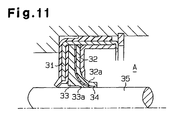
- As shown in Fig. 11, Japanese Unexamined Utility Model Publication No. Hei 5-57520 discloses a lip-shaped seal for sealing rotating
shaft 35 supported by a compressor housing. Character A indicates a closed space defined in the compressor housing. The lip-shaped seal comprises alip member 32 provided in acasing 31 made of a metal. Thelip member 32 is supported by a supportingring 33 made of a resin having a higher stiffness than an elastomer.
Thelip member 32 comprises amain body 32a made of a resin, which has a higher stiffness than an elastomer and which is less permeable to Fluorocarbon, and a synthetic rubber film (fluororubber film) 34 coated on themain body 32a. Asynthetic rubber film 34 is in contact with the outer surface of a rotatingshaft 35. The supportingring 33 has alip portion 33a which is bent and in contact with the outer surface of the rotatingshaft 35. - However, when the lip-shaped seal shown in Fig. 11 is used, the
synthetic rubber film 34 which is permeable to CO2 is in contact with the outer surface of the rotatingshaft 35. Therefore, the lip-shaped seal shown in Fig. 11 is used in the compressor using a CO2 refrigerant, the leakage of CO2 is not satisfactorily prevented. The supportingring 33 made of a resin is in contact with the outer surface of the rotatingshaft 35, but the supportingring 33 is intended to support thelip member 32 and has no satisfactory sealing performance. - Further, Japanese Unexamined Patent Publication No. Hei 8-270799 discloses an O-ring made of a nitrile rubber. The O-ring comprises an inner layer having an acrylonitrile content of 30 to 45 % and an outer layer having an acrylonitrile content of 15 to 25 %. The inner layer having a higher acrylonitrile content is less permeable to gas, and the outer layer having a lower acrylonitrile content is advantageously in close contact with the housing.
- However, the inner layer containing a large quantity of acrylonitrile is hard and poor in flexibility. Such a layer lowers the operation efficiency in the O-ring fitting operation.
- In addition, the outer layer which is more permeable to gas than the inner layer lowers the sealing performance of the O-ring for gas. Further, even when the acrylonitrile content of the inner layer is 30 to 45 %, the sealing performance for CO2 is not satisfactory.
- The present invention provides a sealing member which is advantageous not only in that it improves the efficiency in the fitting operation and has an excellent sealing performance for gas, but also in that it has a simple and small-size structure, especially a sealing member which can be advantageously used in a compressor using a CO2 refrigerant.
- For attaining the above object, the ring-shaped sealing member of the present invention comprises a ring-shaped base material having elastic properties, and a barrier film formed on a surface of the base material. The barrier film is comprised of a resin material which is less permeable to gas than a butyl rubber.
- Another ring-shaped sealing member of the present invention comprises, only at part of the circumferential direction thereof, a stretching portion which is stretchable in the circumferential direction.
-
- Fig. 1(a) is a front view of an O-ring according to a first embodiment of the present invention.
- Fig. 1(b) is a cross-sectional view taken along the
line 1b-1b in Fig. 1(a). - Fig. 1(c) is a partially cross-sectional view showing the state of the O-ring fitted.
- Fig. 2 is a partially cross-sectional view of a lip-shaped seal according to a second embodiment of the present invention.
- Fig. 3 is a partially cross-sectional view of a lip-shaped seal according to a third embodiment of the present invention.
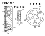
- Fig. 4(a) is a partially cross-sectional view of a compressor having a gasket according to a fourth embodiment of the present invention.
- Fig. 4(b) is an enlarged partially cross-sectional view of the gasket shown in Fig. 4(a).
- Fig. 4(c) is a front view of the gasket shown in Fig. 4(a).
- Fig. 5 is a front view of an O-ring according to a fifth embodiment of the present invention.
- Fig. 6 is a cross-sectional view taken along the line 6-6 in Fig. 5.
- Fig. 7 is a partially cross-sectional view of the O-ring shown in Fig. 6.
- Fig. 8 is a cross-sectional view taken along the line 8-8 in Fig. 5.
- Fig. 9 is a front view of an O-ring according to a sixth embodiment of the present invention.
- Fig. 10 is an enlarged cross-sectional view of an O-ring according to a seventh embodiment of the present invention.
- Fig. 11 is a partially cross-sectional view of a conventional lip-shaped seal.
-
- Hereinbelow, the first embodiment embodying the present invention will be described with reference to Figs. 1(a) to 1(c).
- As shown in Figs. 1(a) and 1(b), O-
ring 1 as a ring-shaped sealing member comprises abase material 2 in a ring-shaped, and agas barrier film 3 which covers the surface of thebase material 2. Thebase material 2 is formed from a material having elastic properties, for example, a rubber or an elastomer. In the present embodiment, thebase material 2 is formed from a hydrogenated nitrile rubber having a relatively low acrylonitrile content (e.g., 20 %). - The
gas barrier film 3 is formed from a resin material which is less permeable to gas, for example, CO2 than a butyl rubber. Specifically, thegas barrier film 3 is comprised of an acrylonitrile-butadiene copolymer having an acrylonitrile content of 50 % or more. The acrylonitrile-butadiene copolymer having a higher acrylonitrile content is much less permeable to CO2, but the elastic properties become poor and thus such a copolymer becomes brittle. Therefore, when thegas barrier film 3 is too large in thickness, the flexibility of the O-ring 1 is lowered, so that the O-ring 1 is not satisfactorily in contact with the contact surface. However, when thegas barrier film 3 has a reduced thickness, the flexibility of the O-ring 1 is not deteriorated, so that the O-ring 1 is advantageously in close contact with the contact surface. Thegas barrier film 3 is less permeable to CO2. Therefore, even when thegas barrier film 3 is small in thickness, the sealing performance of the O-ring 1 for CO2 is satisfactory. - When the acrylonitrile content of the
gas barrier film 3 is increased, the resultantgas barrier film 3 becomes even less permeable to CO2. Therefore, the thickness of thegas barrier film 3 can be further reduced. For example, when the copolymer having an acrylonitrile content of about 70 % is used as thegas barrier film 3, the CO2 permeability of the sealing member comprising thebase material 2 having a cross-section diameter of 1 mm and thegas barrier film 3 having a thickness of 30 µm is about 1/10 of that of the O-ring made of a nitrile rubber disclosed in Japanese Unexamined Patent Publication No. Hei 8-270799. - The
gas barrier film 3 is formed by, for example, applying to the surface of the base material 2 a solution prepared by dissolving an acrylonitrile-butadiene copolymer in a solvent, and removing the solvent by drying. As shown in Fig. 1(c), the O-ring 1 constructed as described above is disposed between housing members 4, 5 which are jointed to each other. The housing members 4, 5 together constitute, for example, a compressor housing. One housing member 4 has a ring-shaped recess portion 4a for containing therein the O-ring 1. When the housing members 4, 5 are jointed to each other, the O-ring 1 is disposed between the housing members 4, 5. A gas in a closed space A formed between the housing members 4, 5 is prevented by thegas barrier film 3 from leaking toward the air B side. - The present embodiment has the following effects.
- The O-
ring 1 comprises thebase material 2 made of a rubber and thegas barrier film 3 made of a resin covering thebase material 2. Thebase material 2 has excellent flexibility, and therefore, the O-ring 1 can be easily fitted into the ring-shaped recess portion 4a. Further, the O-ring 1 is advantageously in close contact with both housing members 4, 5. In addition, the resin forming thegas barrier film 3 is less permeable to gas than a butyl rubber, thus making it possible to surely prevent a gas leakage. - The
gas barrier film 3 is comprised of a resin material which is less permeable to CO2 than a butyl rubber. Therefore, when the O-ring 1 is used in a compressor using CO2 as a refrigerant, the refrigerant can be satisfactorily prevented from leaking. - The
gas barrier film 3 contains acrylonitrile in an amount of 50 % or more. Therefore, thegas barrier film 3 is even less permeable to CO2. By adjusting the acrylonitrile content of the gas barrier film,3, the gas barrier performance of thegas barrier film 3 can be easily adjusted. - The
base material 2 is made of a nitrile rubber, and thegas barrier film 3 is made of an acrylonitrile-butadiene copolymer having an acrylonitrile content of 50 % or more. Therefore, thebase material 2 and thegas barrier film 3 have good affinity with each other, and thegas barrier film 3 is difficult to peel itself off thebase material 2, thus improving the O-ring 1 in durability. - Next, a second embodiment specifically applying the present invention to a lip-shaped seal used in a compressor will be described with reference to Fig. 2. The compressor comprises a
housing 14, and arotating shaft 12 inserted into a throughhole 15 of thehousing 14. Part of the throughhole 15 forms acontainer chamber 15a for containing therein a lip-shapedseal 6. Fig. 2 is a cross-sectional view showing the upper half of the compressor, taken along the shaft line of therotating shaft 12. - The lip-shaped
seal 6 comprises an outer ring 7 made of a metal, afirst sealing member 8 made of a hydrogenated nitrile rubber, asecond sealing member 9 made of a fluororesin, a retaining member 10 made of a metal, and aninner ring 11. The lip-shapedseal 6 is fitted into acontainer portion 15 so that the outer surface of thefirst sealing member 8 is pressed and brought into contact with the sidewall of thecontainer portion 15. A space A in thehousing 14 is kept by the lip-shapedseal 6 away from the outside. The outer ring 7 is insert molded onto thefirst sealing member 8. Thegas barrier film 3 covers the almost entire surface of thefirst sealing member 8. The material for thefirst sealing member 8 is the same as that for thebase material 2 shown in Figs. 1(a) to 1(c). In addition, the material for thegas barrier film 3 is the same as that for thegas barrier film 3 shown in Figs. 1(a) to 1(c). Specifically, thefirst sealing member 8 is a hydrogenated nitrile rubber having an acrylonitrile content of about 20 %. Thegas barrier film 3 is an acrylonitrile-butadiene copolymer having an acrylonitrile content of 50 % or more. - The cross-section of each of the retaining member 10 and the
second sealing member 9 is substantially in an L-shape. Aflange 10a of the retaining member 10 is disposed between the sealingmembers first sealing member 8 is in contact with thefirst sealing member 8. Thesecond sealing member 9 has acontact surface 9a which is in contact with the rotatingshaft 12. In thecontact surface 9a, a spiral groove 13 for guiding a lubricating oil to the space A is formed. - On the surface of the
first sealing member 8, thegas barrier film 3 which is less permeable to gas (CO2) than a butyl rubber is formed. Thefirst sealing member 8 has excellent flexibility, and therefore the lip-shapedseal 6 can be easily fitted into thecontainer chamber 15a. Further, the lip-shapedseal 6 is advantageously in close contact with thehousing 14. In addition, thegas barrier film 3 can satisfactorily prevent a gas from leaking. - Next, the lip-shaped
seal 6 according to a third embodiment of the present invention is shown in Fig. 3. In the present embodiment, thegas barrier film 3 is formed on thesecond sealing member 9 only on the surface thereof opposite to the retaining member 10 and at the tip portion thereof. The present embodiment has the same effects as those of the embodiment shown in Fig. 2. - The
gas barrier film 3 may be formed either on the entire surface of thesecond sealing member 9 including thecontact surface 9a or on the surfaces of thesecond sealing members - Next, a fourth embodiment of the present invention is described with reference to Figs. 4(a) to 4(c). As shown in Fig. 4(a), a compressor comprises a
rear housing 16 and acylinder block 17 which are jointed to each other through abolt 101. Avalve plate assembly 18 is disposed between therear housing 16 and thecylinder block 17. Thevalve plate assembly 18 comprises amain plate 21 in which an intake port and a discharge port are formed, and agasket 19. - As shown in Fig. 4(b), the
gasket 19 comprises abase material 20 in which arubber layer 20b is formed on the surface of ametal plate 20a, and thegas barrier film 3 formed on the surface of thebase material 20. As shown in Fig. 4(c), thegasket 19 hasholes 22 at positions corresponding to the intake port and the discharge port formed in themain plate 21. Further, thegasket 19 has a throughhole 23 through which thebolt 101 is inserted. In Fig. 4(b), therubber layer 20b and thegas barrier film 3 are shown so that they have substantially the same thickness, but the thickness of thegas barrier film 3 is actually one-several tens or less of the thickness of therubber layer 20b. - In the present embodiment, the
gas barrier film 3 suppresses a leakage of the gas in the compressor away from the housing. In addition, therubber layer 20b has excellent flexibility, and therefore thegasket 19 is advantageously in close contact with therear housing 16 and thecylinder block 17. - Next, a fifth embodiment of the present invention will be described with reference to Figs. 5 to 8. Like the embodiment shown in Figs. 1(a) to 1(c), the present embodiment is directed to an O-ring for sealing between the housing members 4 and 5. An O-
ring 41 comprises two stretchingportions 42 which are stretchable, and twomultilayer portions 43 which are not stretchable. - The two
multilayer portions 43 constitute most of the circumferential direction of the O-ring 41. As shown in Figs. 5 and 7, themultilayer portion 43 comprises, as a barrier material, acore material 44 comprised of a metal material which is less permeable to CO2, and, as an elastomer, arubber film 45 which covers the surface of thecore material 44. Therubber film 45 is formed from, for example, a rubber material, such as a nitrile rubber or a hydrogenated nitrile rubber. Thecore material 44 is a circular arc metallic bar having a cross-section in a circular form. - As shown in Figs. 5 to 8, the stretching
portions 42 connect together themultilayer portions 43. The stretchingportion 42 is made of the same material as that for therubber film 45, and integrally formed with therubber film 45. - As a method for producing the O-
ring 41, for example, insert molding is employed. A rubber material is injected into a mold having placed therein thecore material 44 to shape the O-ring 41. - The stretching
portion 42 has an elastic modulus far larger than that of thecore material 44 made of a metal. Therefore, as the stretchingportions 42 are stretched, bothmultilayer portions 43 move closer to or separate from each other. - As described above, the stretching
portions 42 are formed on part of the O-ring 41, and thecore material 44 which is less permeable to CO2 on the remaining portion. Thus, the O-ring 41 has flexibility and is less permeable to CO2. Therefore, there is no need to dispose the multiple O-rings or increase the O-ring in diameter for improving the sealing performance. Thus, a space in which the O-ring 41 is placed need not be large. Further, the seal structure is simple, as compared to the construction in which the multiple O-rings are disposed. - The
rubber film 45 for themultilayer portions 43 is integrally molded with the stretchingportions 42. Therefore, the stretchingportions 42 and themultilayer portions 43 are firmly connected to each other. The O-ring 41 can be easily formed by insert molding, thus improving the productivity of the O-ring 41. - The
core material 44 is covered with therubber film 45. Therefore, the O-ring 41 is advantageously in close contact with the contact surface. Thus, a high sealing performance can be secured. - The O-
ring 41 has a plurality of stretchingportions 42. Therefore, the O-ring 41 is easy to stretch, thus improving the efficiency in the fitting operation. - Even if the O-
ring 41 has a shape slightly different from the shape of the portion to which the O-ring 41 is fitted, if the number of the stretchingportions 42 is large, the O-ring 41 can be easily deformed so as to fit the shape of the portion to which the O-ring 41 is fitted. As a result, the sealing performance of the O-ring 41 is enhanced. - For example, in the compressor using CO2 as a refrigerant, the pressure of CO2 is extremely high. It is especially effective to apply the O-
ring 41 of the present embodiment having excellent sealing performance to the above compressor. - Next, a sixth embodiment of the present invention is described with reference to Fig. 9. The present embodiment is an example of modification of Figs. 5 to 8. In the present embodiment, the O-
ring 41 has threemultilayer portions 43 and the stretchingportions 42. By virtue of having such a construction, the O-ring 41 is more easily deformed than the O-ring 41 in Figs. 5 to 8, and the efficiency in the fitting operation is further improved, as compared to that in the embodiment in Figs. 5 to 8. - Next, a seventh embodiment of the present invention is described with reference to Fig. 10. In the present embodiment, the
core material 44 is formed to be hollow, and the inner space of thecore material 44 is filled with arubber material 46 which is comprised of the same material as that for therubber film 45. Therubber material 46 is molded, for example, simultaneously with the molding of therubber film 45 in the insert molding of the O-ring 41. Therubber film 45 and therubber material 46 are integrally formed with the rubber forming the stretchingportions 42, so that the stretchingportions 42 and themultilayer portions 43 are connected to one another more firmly. Thecore material 44 may be filled with therubber material 16 only around both end portions of thecore material 44. - The embodiments may be modified, for example, as follows.
- The present invention is not limited to the O-
rings - The material for the
base material 2 in the embodiment shown in Figs. 1(a) to 1(c) is not limited to the hydrogenated nitrile rubber but may be another rubber. Further, the material for thebase material 20 shown in Fig. 4(b) may be another rubber. When a hydrogenated nitrile rubber or a nitrile rubber is used, the acrylonitrile content is not limited to 20 % but preferably 15 to 49 % which exhibits appropriate elastic properties. - In each of the embodiments shown in Figs. 1(a) to 4(c), the acrylonitrile content of the
gas barrier film 3 may be 50 % or more, preferably 60 % or more, further preferably 70 % or more. - The
gas barrier film 3 is not limited to the acrylonitrile-butadiene copolymer having an acrylonitrile content of 50 % or more but may be another acrylonitrile copolymer. For example, it may be an acrylonitrile-styrene copolymer or acrylonitrile-butadiene-styrene copolymer having an acrylonitrile content of 50 % or more. - The material for the
gas barrier film 3 is not limited to the acrylonitrile copolymer but may be any resin material as long as the resin material is less permeable to gas than a butyl rubber, and, for example, it may be nylon or polyvinylidene chloride. - The structure of the
gas barrier film 3 is not limited to a structure comprising one layer but may be a structure comprising a plurality of layers having different material compositions. For example, when an acrylonitrile-butadiene copolymer is used as thegas barrier film 3, the outermost layer may be formed from a material having the highest acrylonitrile content and the inner layers may be formed from materials having acrylonitrile contents which reduce such that the innermost layer has the smallest content. In this case, since the compositions of the adjacent layers are close to one another, thegas barrier film 3 is advantageously in close contact with thebase material 2. - In each of the embodiments shown in Figs. 5 to 10, the
core material 44 may not be made of a metal. For example, thecore material 44 may be made of a resin as long as it is less permeable to gas. - In each of the embodiments shown in Figs. 5 to 10, the
rubber film 15 may not be formed on the surface of thecore material 44. - The O-
ring 41 may have only one stretchingportion 42. - The O-
ring 41 is not limited to one which is less permeable to CO2. For example, it may be one which is less permeable to Fluorocarbon gas.
Claims (12)
- A ring-shaped sealing member comprising:a ring-shaped base material having elastic properties; anda barrier film which is formed on a surface of said base material and is comprised of a resin material, wherein said resin material is less permeable to gas than a butyl rubber.
- The sealing member according to claim 1, wherein said base material is made of a rubber.
- The sealing member according to claim 1 or 2, wherein said resin material constituting said barrier film is less permeable to carbon dioxide than a butyl rubber.
- The sealing member according to any one of claims 1 to 3, wherein said barrier film contains acrylonitrile in an amount of 50 % or more.
- The sealing member according to any one of claims 1 to 4, wherein said base material is comprised of a nitrile rubber, and wherein said barrier film is comprised of an acrylonitrile-butadiene copolymer containing acrylonitrile in an amount of 50 % or more.
- The sealing member according to any one of claims 1 to 5, which is an O-ring.
- The sealing member according to any one of claims 1 to 5, which is a lip-shaped seal.
- A ring-shaped sealing member comprising, only at part of the circumferential direction thereof, a stretching portion which is stretchable in the circumferential direction.
- The sealing member according to claim 8, wherein a portion other than said stretching portion is formed from an elastomer and a barrier material which is less permeable to gas.
- The sealing member according to claim 9, wherein said elastomer covers said barrier material.
- The sealing member according to any one of claims 8 to 10, wherein said stretching portion is one of a plurality of stretching portions disposed in the circumferential direction of said sealing member at a predetermined interval.
- The sealing member according to any one of claims 8 to 11, wherein said portion other than said stretching portion is formed from a material which is less permeable to carbon dioxide.
Applications Claiming Priority (5)
| Application Number | Priority Date | Filing Date | Title |
|---|---|---|---|
| JP2000167362A JP2001349437A (en) | 2000-06-05 | 2000-06-05 | Seal material |
| JP2000167362 | 2000-06-05 | ||
| JP2000181466 | 2000-06-16 | ||
| JP2000181466A JP2002005294A (en) | 2000-06-16 | 2000-06-16 | Ring-type seal material |
| PCT/JP2001/004603 WO2001094814A1 (en) | 2000-06-05 | 2001-05-31 | Seal member |
Publications (1)
| Publication Number | Publication Date |
|---|---|
| EP1213515A1 true EP1213515A1 (en) | 2002-06-12 |
Family
ID=26593303
Family Applications (1)
| Application Number | Title | Priority Date | Filing Date |
|---|---|---|---|
| EP20010934458 Withdrawn EP1213515A1 (en) | 2000-06-05 | 2001-05-31 | Seal member |
Country Status (3)
| Country | Link |
|---|---|
| US (1) | US20020106526A1 (en) |
| EP (1) | EP1213515A1 (en) |
| WO (1) | WO2001094814A1 (en) |
Cited By (4)
| Publication number | Priority date | Publication date | Assignee | Title |
|---|---|---|---|---|
| EP1469247A1 (en) * | 2003-04-14 | 2004-10-20 | Voss Automotive GmbH | Pipe coupling system |
| US7258371B1 (en) | 2003-04-14 | 2007-08-21 | Voss Automotive Gmbh | Connection system |
| GB2461775A (en) * | 2008-07-16 | 2010-01-20 | Walker & Co James | An elastomeric seal which remains flexible at low temperatures |
| US8116947B2 (en) | 2002-10-21 | 2012-02-14 | Autoliv Development Ab | Safety arrangement for a vehicle using separate sensing and control units |
Families Citing this family (9)
| Publication number | Priority date | Publication date | Assignee | Title |
|---|---|---|---|---|
| JP2001150595A (en) * | 1999-11-30 | 2001-06-05 | Tokai Rubber Ind Ltd | Packing structure |
| CA2453425A1 (en) * | 2001-07-13 | 2003-01-23 | Delaware Capital Formation, Inc. | Elastomeric sealing element for gas compressor valve |
| JP5021962B2 (en) * | 2006-06-16 | 2012-09-12 | 株式会社小松製作所 | Floating seal |
| US20080007011A1 (en) * | 2006-07-07 | 2008-01-10 | Henry Buermann | Compressed gas cylinder valve seal having elastomeric overmolded surface |
| CA2796749C (en) * | 2010-04-19 | 2017-01-10 | Barbara Carey Stachowski | Expanding hair band |
| US9404334B2 (en) * | 2012-08-31 | 2016-08-02 | Baker Hughes Incorporated | Downhole elastomeric components including barrier coatings |
| DE102017213159A1 (en) * | 2017-07-31 | 2019-01-31 | Siemens Aktiengesellschaft | Gasket for gas-insulated electrical system |
| DE102018219779A1 (en) * | 2018-11-19 | 2020-05-20 | Zf Friedrichshafen Ag | Sealing device, electric machine and drive device |
| CN113631844A (en) * | 2019-03-29 | 2021-11-09 | Abb瑞士股份有限公司 | Joint, electric motor, industrial robot and method of installing seal |
Family Cites Families (6)
| Publication number | Priority date | Publication date | Assignee | Title |
|---|---|---|---|---|
| JPS54122246U (en) * | 1978-02-17 | 1979-08-27 | ||
| JPS6322877A (en) * | 1986-06-18 | 1988-01-30 | Alpha Giken:Kk | Adhesive for molded article of high nitrile copolymer |
| JPH0324370A (en) * | 1989-06-20 | 1991-02-01 | Yokohama Rubber Co Ltd:The | Gas resistance permeable o-ring and its manufacture |
| EP0430349A3 (en) * | 1989-11-27 | 1991-10-16 | Stamicarbon B.V. | Process for the polymerization and recovery of nitrile rubber containing high bound acrylonitrile |
| JPH0685966U (en) * | 1993-05-28 | 1994-12-13 | 株式会社マルサン | Floating gasket |
| JP3516149B2 (en) * | 1994-04-25 | 2004-04-05 | 甲南電機株式会社 | Composite packing |
-
2001
- 2001-05-31 WO PCT/JP2001/004603 patent/WO2001094814A1/en not_active Ceased
- 2001-05-31 US US10/048,905 patent/US20020106526A1/en not_active Abandoned
- 2001-05-31 EP EP20010934458 patent/EP1213515A1/en not_active Withdrawn
Non-Patent Citations (1)
| Title |
|---|
| See references of WO0194814A1 * |
Cited By (7)
| Publication number | Priority date | Publication date | Assignee | Title |
|---|---|---|---|---|
| US8116947B2 (en) | 2002-10-21 | 2012-02-14 | Autoliv Development Ab | Safety arrangement for a vehicle using separate sensing and control units |
| EP1469247A1 (en) * | 2003-04-14 | 2004-10-20 | Voss Automotive GmbH | Pipe coupling system |
| US7258371B1 (en) | 2003-04-14 | 2007-08-21 | Voss Automotive Gmbh | Connection system |
| GB2461775A (en) * | 2008-07-16 | 2010-01-20 | Walker & Co James | An elastomeric seal which remains flexible at low temperatures |
| WO2010007439A3 (en) * | 2008-07-16 | 2010-03-11 | James Walker & Co. Ltd. | Seal |
| CN102197249A (en) * | 2008-07-16 | 2011-09-21 | 詹姆斯沃克有限公司 | Seal |
| CN102197249B (en) * | 2008-07-16 | 2015-04-01 | 詹姆斯沃克有限公司 | Seal |
Also Published As
| Publication number | Publication date |
|---|---|
| US20020106526A1 (en) | 2002-08-08 |
| WO2001094814A1 (en) | 2001-12-13 |
Similar Documents
| Publication | Publication Date | Title |
|---|---|---|
| US20020106526A1 (en) | Seal member | |
| US9194495B2 (en) | Fluid pressure apparatus | |
| US6543786B2 (en) | Installation structure of lip type seal | |
| EP1944534B1 (en) | Rotation shaft seal | |
| CN1100952C (en) | Shaft seal and its specific compressor | |
| US6666459B1 (en) | Radial shaft seal | |
| US20040130101A1 (en) | Shaft sealing assembly | |
| CA2065733C (en) | Annular support for a seal for a tilt piston | |
| US20040160016A1 (en) | Bonded PTFE radial shaft seal | |
| US6322082B1 (en) | High pressure seal with contoured stamping I. D. | |
| CN1105252C (en) | Shaft sealing structure | |
| JP2001193842A (en) | Lip type seal | |
| JP2000074223A (en) | Oil seal | |
| US20020182072A1 (en) | Seal device | |
| JP3415266B2 (en) | Rotary shaft seal | |
| JPH11101348A (en) | Sealing member | |
| US20010050464A1 (en) | Housing seal | |
| JP2001349437A (en) | Seal material | |
| CN112539153A (en) | Compressor combined piston ring | |
| WO2003054427A1 (en) | Sealing member | |
| JP2999672B2 (en) | Rotary shaft seal | |
| JP2007198264A (en) | Mechanical seal device for compressor | |
| CN1261707C (en) | Sealing device | |
| JP2002031244A (en) | Shaft seal | |
| CN212106261U (en) | Shaft seal structure and electric compressor |
Legal Events
| Date | Code | Title | Description |
|---|---|---|---|
| PUAI | Public reference made under article 153(3) epc to a published international application that has entered the european phase |
Free format text: ORIGINAL CODE: 0009012 |
|
| 17P | Request for examination filed |
Effective date: 20020204 |
|
| AK | Designated contracting states |
Kind code of ref document: A1 Designated state(s): AT BE CH CY DE DK ES FI FR GB GR IE IT LI LU MC NL PT SE TR |
|
| RBV | Designated contracting states (corrected) |
Designated state(s): DE FR IT |
|
| STAA | Information on the status of an ep patent application or granted ep patent |
Free format text: STATUS: THE APPLICATION IS DEEMED TO BE WITHDRAWN |
|
| 18D | Application deemed to be withdrawn |
Effective date: 20041201 |