EP1213446A2 - Variable stator vane bushing - Google Patents
Variable stator vane bushing Download PDFInfo
- Publication number
- EP1213446A2 EP1213446A2 EP01310191A EP01310191A EP1213446A2 EP 1213446 A2 EP1213446 A2 EP 1213446A2 EP 01310191 A EP01310191 A EP 01310191A EP 01310191 A EP01310191 A EP 01310191A EP 1213446 A2 EP1213446 A2 EP 1213446A2
- Authority
- EP
- European Patent Office
- Prior art keywords
- bushing
- stator vane
- vane
- accordance
- variable stator
- Prior art date
- Legal status (The legal status is an assumption and is not a legal conclusion. Google has not performed a legal analysis and makes no representation as to the accuracy of the status listed.)
- Granted
Links
Images


Classifications
-
- F—MECHANICAL ENGINEERING; LIGHTING; HEATING; WEAPONS; BLASTING
- F01—MACHINES OR ENGINES IN GENERAL; ENGINE PLANTS IN GENERAL; STEAM ENGINES
- F01D—NON-POSITIVE DISPLACEMENT MACHINES OR ENGINES, e.g. STEAM TURBINES
- F01D17/00—Regulating or controlling by varying flow
- F01D17/10—Final actuators
- F01D17/12—Final actuators arranged in stator parts
- F01D17/14—Final actuators arranged in stator parts varying effective cross-sectional area of nozzles or guide conduits
- F01D17/16—Final actuators arranged in stator parts varying effective cross-sectional area of nozzles or guide conduits by means of nozzle vanes
- F01D17/162—Final actuators arranged in stator parts varying effective cross-sectional area of nozzles or guide conduits by means of nozzle vanes for axial flow, i.e. the vanes turning around axes which are essentially perpendicular to the rotor centre line
-
- F—MECHANICAL ENGINEERING; LIGHTING; HEATING; WEAPONS; BLASTING
- F16—ENGINEERING ELEMENTS AND UNITS; GENERAL MEASURES FOR PRODUCING AND MAINTAINING EFFECTIVE FUNCTIONING OF MACHINES OR INSTALLATIONS; THERMAL INSULATION IN GENERAL
- F16C—SHAFTS; FLEXIBLE SHAFTS; ELEMENTS OR CRANKSHAFT MECHANISMS; ROTARY BODIES OTHER THAN GEARING ELEMENTS; BEARINGS
- F16C17/00—Sliding-contact bearings for exclusively rotary movement
- F16C17/12—Sliding-contact bearings for exclusively rotary movement characterised by features not related to the direction of the load
- F16C17/24—Sliding-contact bearings for exclusively rotary movement characterised by features not related to the direction of the load with devices affected by abnormal or undesired positions, e.g. for preventing overheating, for safety
-
- F—MECHANICAL ENGINEERING; LIGHTING; HEATING; WEAPONS; BLASTING
- F16—ENGINEERING ELEMENTS AND UNITS; GENERAL MEASURES FOR PRODUCING AND MAINTAINING EFFECTIVE FUNCTIONING OF MACHINES OR INSTALLATIONS; THERMAL INSULATION IN GENERAL
- F16C—SHAFTS; FLEXIBLE SHAFTS; ELEMENTS OR CRANKSHAFT MECHANISMS; ROTARY BODIES OTHER THAN GEARING ELEMENTS; BEARINGS
- F16C33/00—Parts of bearings; Special methods for making bearings or parts thereof
- F16C33/02—Parts of sliding-contact bearings
- F16C33/04—Brasses; Bushes; Linings
- F16C33/20—Sliding surface consisting mainly of plastics
- F16C33/201—Composition of the plastic
Definitions
- This invention relates generally to gas turbine engine variable stator vane assemblies and, more particularly, to bushings used within the variable stator vane assembly.
- Gas turbine engines include a high pressure compressor, a combustor, and a high pressure turbine.
- the high pressure compressor includes a rotor, and a plurality of stages.
- the rotor is surrounded by a casing, and each stage includes a row of rotor blades and a row of stator vanes.
- the casing supports the stator vanes, and the rotor supports the rotor blades.
- the stator vane rows are between the rotor blade rows and direct air flow toward a subsequent downstream rotor blade row.
- the stator vane rows are exposed to a water/air mist mixture.
- Variable stator vane assemblies are utilized to control the amount of air flowing through the compressor to facilitate optimizing performance of the compressor.
- Each variable stator vane assembly includes a variable stator vane which extends between adjacent rotor blades.
- the variable stator vane is rotatable about an axis such that the stator vane is positionable in a plurality of orientations to direct air flow through the compressor.
- variable vane assemblies include a variable vane, a bushing, and a spacer.
- the bushing extends between the variable vane and the casing, and between the spacer and the casing, to prevent both the spacer and the vane from contacting the casing. Because of wear considerations, the bushings are typically fabricated from materials having high durability and low friction. However, because the variable stator vane assembly is exposed to the water/air mixture, to minimize corrosion and oxidation, the bushings are also typically fabricated from non-metallic materials.
- a variable stator vane assembly for a gas turbine engine includes a bushing that facilitates extending a useful life of the variable stator vane assembly.
- the stator vane assembly includes a spacer and a vane secured to an engine casing.
- the bushing is between the spacer and vane, and prevents the spacer and the vane from contacting the engine casing.
- the bushing is fabricated such that at least a portion of the bushing is electrically conductive.
- a water/air mixture flowing through the engine may cause a static electrical charge to develop on metallic components of the variable stator vane assembly.
- the bushing is fabricated such that at least a portion of the bushing is electrically conductive, a conductive path is realized through the bushing, such that electrical charges induced within the variable stator vane assembly are discharged through the bushing to ground.
- the bushing facilitates reducing or eliminating electrical charges within the variable stator vane assembly in a cost effective and reliable manner.
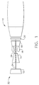
- Figure 1 is a schematic illustration of a gas turbine engine 10 including a low pressure compressor 12, a high pressure compressor 14, and a combustor assembly 16.
- Engine 10 also includes a high pressure turbine 18, and a low pressure turbine 20 arranged in a serial, axial flow relationship. Compressor 12 and turbine 20 are coupled by a first shaft 24, and compressor 14 and turbine 18 are coupled by a second shaft 26.
- engine 10 is an LM6000 engine commercially available from General Electric Company, Cincinnati, Ohio.
- FIG 2 is a schematic view of a section of high pressure compressor 14 for turbine engine.
- Compressor 14 includes a plurality of stages 50, and each stage 50 includes a row of rotor blades 52 and a row of variable stator vane assemblies 56.
- Rotor blades 52 are typically supported by rotor disks 58, and are connected to rotor shaft 26.
- Rotor shaft 26 is a high pressure shaft that is also connected to high pressure turbine 18 (shown in Figure 1).
- Rotor shaft 26 is surrounded by a stator casing 62 that supports variable stator vane assemblies 56.
- Each variable stator vane assembly 56 includes a variable vane 74 and a vane stem 76. Vane stem 76 protrudes through an opening 78 in casing 62.
- Each variable vane assembly 56 also includes a lever arm 80 extending from variable vane 74 that is utilized to rotate variable vanes 74. Vanes 74 are oriented relative to a flow path through compressor 14 to control air flow therethrough. In addition, at least some vanes 74 are attached to an inner casing 82.
- FIG 3 is an enlarged schematic view of variable stator vane assembly 56. More specifically, in one embodiment, variable stator vane assemblies 56 are utilized in an inlet guide vane (IGV), a first, and a second stage 50 (shown in Figure 2) of an LM 6000 engine commercially available from General Electric Company, Cincinnati, Ohio. Each variable stator vane assembly 56 includes variable vane 74 and a washer 98 positioned on variable vane 74.
- Casing 62 supports variable vane 74 and includes a first recessed portion 100, an inner wall 102, and a second recessed portion 104. Openings 78 are formed by inner wall 102. Washer 98 includes a first portion 108 and a second portion 110.
- Washer first portion 108 seats within first recessed portion 100 and separates variable vane 74 from casing 62.
- Washer second portion 110 extends substantially perpendicularly from washer first portion 108 into opening 78. Washer second portion 110 contacts inner wall 102 to separate variable vane 74 from casing 62.
- Variable stator vane assembly 56 also includes a bushing 120, described in more detail below, having an annular first portion 122 and an annular second portion 124 that is substantially cylindrical.
- Variable vane assembly bushing first portion 122 extends radially outward from bushing second portion 124.
- First portion 122 is positioned on casing 62 and extends along second recessed portion 62.
- a spacer 126 contacts bushing 120 and is separated from casing 62 by bushing 120.
- bushing 120 contacts washer 98 and separates a portion of washer 98 from spacer 126.
- Variable vane 74 also includes a ledge 128 including an outer wall 130 and a spacer seating surface 132. Ledge 128 surrounds vane stem 76, and vane stem 76 and ledge 128 extend through casing opening 78.
- Bushing second portion 124 extends in close tolerance along casing inner wall 102 and prevents an outer wall 130 of ledge 128 from contacting casing inner wall 102.
- Variable vane assembly lever arm 80 is positioned around vane stem 76 and in contact with spacer 126. Lever arm 80 is utilized to adjust the angle of vane 74, and thus alter the flow of air through the compressor.
- variable vane assembly 56 includes a sleeve 138 that contacts lever arm 80 and a lever arm nut 140 that contacts sleeve 138. Lever arm nut 140 cooperates with vane stem 76 and maintains variable vane assembly 56 in contact with casing 62.
- Figure 4 is an enlarged cross-sectional view of an exemplary embodiment of a variable vane assembly bushing 120.
- Bushing 120 includes a first layer 170, a second layer 172, and a third layer 176. More specifically, variable stator vane assembly bushing 120 is fabricated from a matrix formed of at least three different layers. In one embodiment, Teflon fibers and glass fibers are included in the matrix used in fabricating variable vane assembly bushing 120.
- Bushing 120 is impregnated with a resin to bond the matrix.
- the resin is a polyimide resin Skybord 703 commercially available from Monsanto Corp., St. Louis, Missouri.
- An amount of conductive material is added to the resin.
- the conductive material includes, but is not limited to, graphite or aluminum.
- the amount of conductive material added to the resin is pre-selected to ensure that as the resin cures to bond the materials used in fabricating bushing 120, the conductive material is homogeneously distributed throughout bushing 120. Accordingly, a conductive path is realized through bushing first portion 122 and bushing second portion 124. More specifically, the amount of conductive material added to the resin is variable and selected such that to enable bushing 120 to conduct a pre-determined amount of current with a pre-determined resistance. In addition, the addition of resin to bushing 120 facilitates increasing a durability of bushing 120 and lowering a coefficient of friction of bushing 120.
- variable stator vane assembly 56 During operation, as variable stator vane assembly 56 is exposed to a water/air mixture flowing through engine 10 (shown in Figures 1 and 2), a static charge may develop on metallic components of variable vane assembly 56 (shown in Figures 2 and 3). Continued exposure to the static charge may result in arcing and may result in premature failure of the variable stator vane assembly, triggering internal fire alarms, or detonating external fuel/air mixtures that may be present. Because material used in fabricating bushing 120 is bonded with resin including conductive material, a conductive path is realized through bushing 120, electrical charges induced within variable stator vane assembly 56 are discharged through bushing 120 to ground. As a result, bushing 120 facilitates extending a useful service life for variable stator vane assembly 56, and reduces or eliminates the previously mentioned failure modes, since electrical charge build-up of metallic components within variable stator vane assembly 56 is substantially reduced, or eliminated.
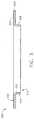
- FIG. 5 is side view of an alternative embodiment of a bushing 200 that may be used with variable stator vane assembly 56 (shown in Figures 2 and 3).
- Bushing 200 is substantially similar to bushing 120 shown in Figures 3 and 4, and components in bushing 200 that are identical to components of bushing 120 are identified in Figure 5 using the same reference numerals used in Figures 3 and 4. Accordingly, bushing 200 includes first portion 122 and second portion 124.
- bushing 200 includes first layer 170 (shown in Figure 4), second layer 172 (shown in Figure 4), and third layer 176 (shown in Figure 4) and is fabricated from a matrix formed of at least three different layers.
- Bushing 200 is coated with a conductive material.
- the coating is Xylan 1401 commercially available from Whitford Corporation, West Chester, Pennsylvania.
- bushing first portion 122 is coated with the conductive material. More specifically, bushing first portion 122 includes an upper surface 202, an outer edge 204, and a lower surface 206.
- the conductive material coating is applied to bushing first portion upper surface 202, outer edge 204, and lower surface 206, but is not applied to bushing second portion 124 or to a sidewall 210 defining a bore 212 extending concentrically through bushing 200.
- the coating acts as an electrical conductor such that a conductive path is realized on bushing 200.
- the coating is selected to conduct a pre-determined amount of current with a pre-determined resistance. More specifically, the conductive path extends between vane spacer 126 (shown in Figure 3) around bushing projection edge 204 to bushing first portion lower surface 206. Because bushing first portion lower surface 206 is adjacent casing 62 (shown in Figure 3), the conductive path extends through casing 62 to ground.
- the coating is fabricated from a low friction material, the coating also acts as a wear surface against casing 62 and vane spacer 126.
- bushing 200 is positioned in tight tolerance between casing inner wall 102 (shown in Figure 3) and vane ledge outer wall 130 (shown in Figure 3), because the coating is not applied against bushing bore sidewall 210 or bushing second portion 124, the coating may be applied to existing bushings (not shown) without compromising a clearance fit between vane ledge outer wall 130 and casing 62.
- the above-described variable stator vane assembly is cost-effective and highly reliable.
- the stator vane assembly includes a bushing that forms a conductive path between the variable stator vane spacer and the casing.
- the bushing facilitates discharging electrical charges from the variable stator vane assembly to ground. More specifically, the bushing facilitates substantially reducing or eliminated electrical charge build-up of metallic components within the variable stator vane assembly. As a result, the bushing facilitates reducing or eliminating electrical charges within the variable stator vane assembly in a cost effective and reliable manner.
Landscapes
- Engineering & Computer Science (AREA)
- General Engineering & Computer Science (AREA)
- Mechanical Engineering (AREA)
- Structures Of Non-Positive Displacement Pumps (AREA)
- Turbine Rotor Nozzle Sealing (AREA)
Abstract
Description
Claims (10)
- A method for manufacturing a bushing (120) for a gas turbine engine (10) variable stator vane (56), the bushing including a substantially cylindrical portion (124) and an annular projection (122) extending radially outward from the cylindrical portion, said method comprising the steps of:forming a plurality of layers (170, 172, 176) from at least one material; andforming the bushing from the material layer such that at least a portion of the bushing is electrically conductive.
- A bushing (120) for a gas turbine engine (10) variable stator vane (56), said bushing comprising a body comprising an annular projection (122) and a substantially cylindrical portion (124), said annular projection extending radially outward from said substantially cylindrical portion, at least a portion of said bushing being electrically conductive.
- A variable stator vane (56) in accordance with Claim 2 wherein said bushing (120) further comprises a plurality of layers (170, 172, 176).
- A bushing (120) in accordance with Claim 2 wherein said bushing further comprises a plurality of layers (170, 172, 176) formed from a combination of at least three materials.
- A bushing (120) in accordance with Claim 48 wherein said plurality of layers (170, 172, 176) are bonded with a resin including a conductive material.
- A bushing (120) in accordance with Claim 5 wherein the conductive material is substantially homogenous throughout said bushing.
- A bushing (120) in accordance with Claim 2 wherein said bushing body is electrically conductive.
- A bushing (120) in accordance with Claim 2 wherein said bushing annular projection (122) is coated with a conductive material.
- A bushing (120) in accordance with Claim 2 wherein said bushing is configured to electrically conduct a pre-determined current with a pre-determined resistance.
- A variable stator vane (56) for a gas turbine engine (10) including a casing (62), said stator vane comprising:a spacer (126);a movable vane (74); anda bushing (120) between said spacer and said vane, said bushing configured to prevent said spacer and said vane from contacting the gas turbine engine casing, said bushing being in accordance with any one of claims 2 to 9.
Applications Claiming Priority (2)
| Application Number | Priority Date | Filing Date | Title |
|---|---|---|---|
| US733452 | 2000-12-08 | ||
| US09/733,452 US6474941B2 (en) | 2000-12-08 | 2000-12-08 | Variable stator vane bushing |
Publications (3)
| Publication Number | Publication Date |
|---|---|
| EP1213446A2 true EP1213446A2 (en) | 2002-06-12 |
| EP1213446A3 EP1213446A3 (en) | 2004-01-07 |
| EP1213446B1 EP1213446B1 (en) | 2008-03-12 |
Family
ID=24947660
Family Applications (1)
| Application Number | Title | Priority Date | Filing Date |
|---|---|---|---|
| EP01310191A Expired - Lifetime EP1213446B1 (en) | 2000-12-08 | 2001-12-05 | Variable stator vane bushing |
Country Status (5)
| Country | Link |
|---|---|
| US (1) | US6474941B2 (en) |
| EP (1) | EP1213446B1 (en) |
| JP (1) | JP4108324B2 (en) |
| CA (1) | CA2364159C (en) |
| DE (1) | DE60133168T2 (en) |
Cited By (3)
| Publication number | Priority date | Publication date | Assignee | Title |
|---|---|---|---|---|
| US5212968A (en) * | 1990-07-04 | 1993-05-25 | Shima Seiki Mfg., Ltd. | Presser controller of a carriage in a flat knitting machine |
| WO2004085090A1 (en) * | 2003-03-27 | 2004-10-07 | Minebea Co Ltd. | A bush and method of manufacturing a bush |
| DE102014218319A1 (en) * | 2014-09-12 | 2015-09-24 | Schaeffler Technologies AG & Co. KG | Sliding bearing component and bearing arrangement with this |
Families Citing this family (28)
| Publication number | Priority date | Publication date | Assignee | Title |
|---|---|---|---|---|
| US6670733B2 (en) * | 2001-09-27 | 2003-12-30 | Reliance Electric Technologies, Llc | System and method of reducing bearing voltage |
| US7220098B2 (en) | 2003-05-27 | 2007-05-22 | General Electric Company | Wear resistant variable stator vane assemblies |
| US7094022B2 (en) * | 2003-05-27 | 2006-08-22 | General Electric Company | Variable stator vane bushings and washers |
| US20060029494A1 (en) * | 2003-05-27 | 2006-02-09 | General Electric Company | High temperature ceramic lubricant |
| US7207770B2 (en) * | 2003-05-27 | 2007-04-24 | General Electric Company | Variable stator vane bushings and washers |
| US7163369B2 (en) * | 2003-05-27 | 2007-01-16 | General Electric Company | Variable stator vane bushings and washers |
| US20050129340A1 (en) * | 2003-12-10 | 2005-06-16 | Arnold Robert A. | Hourglass bearing |
| US7125222B2 (en) * | 2004-04-14 | 2006-10-24 | General Electric Company | Gas turbine engine variable vane assembly |
| US7360990B2 (en) * | 2004-10-13 | 2008-04-22 | General Electric Company | Methods and apparatus for assembling gas turbine engines |
| US7322588B2 (en) * | 2004-11-24 | 2008-01-29 | General Motors Corporation | Mounting assembly for steering system of vehicles |
| US7543992B2 (en) * | 2005-04-28 | 2009-06-09 | General Electric Company | High temperature rod end bearings |
| US7278819B2 (en) * | 2005-07-05 | 2007-10-09 | General Electric Company | Variable stator vane lever arm assembly and method of assembling same |
| US8327538B2 (en) * | 2005-10-17 | 2012-12-11 | General Electric Company | Methods to facilitate extending gas turbine engine useful life |
| US8517661B2 (en) | 2007-01-22 | 2013-08-27 | General Electric Company | Variable vane assembly for a gas turbine engine having an incrementally rotatable bushing |
| US7713022B2 (en) * | 2007-03-06 | 2010-05-11 | United Technologies Operations | Small radial profile shroud for variable vane structure in a gas turbine engine |
| US8197196B2 (en) * | 2007-08-31 | 2012-06-12 | General Electric Company | Bushing and clock spring assembly for moveable turbine vane |
| US8061975B2 (en) * | 2007-08-31 | 2011-11-22 | General Electric Company | Slipring bushing assembly for moveable turbine vane |
| US20090288628A1 (en) * | 2008-05-21 | 2009-11-26 | Rolls-Royce North American Technologies, Inc. | Electrically isolated rotor ground |
| WO2010025339A1 (en) * | 2008-08-29 | 2010-03-04 | E. I. Du Pont De Nemours And Company | Composite parts for airplane engines |
| KR20110053370A (en) * | 2008-08-29 | 2011-05-20 | 이 아이 듀폰 디 네모아 앤드 캄파니 | Composite Parts for Aircraft Engines |
| US20100275574A1 (en) * | 2009-04-30 | 2010-11-04 | General Electric Company | Borescope plug with bristles |
| US8328512B2 (en) * | 2009-06-05 | 2012-12-11 | United Technologies Corporation | Inner diameter shroud assembly for variable inlet guide vane structure in a gas turbine engine |
| FR2964411B1 (en) * | 2010-09-06 | 2012-08-24 | Messier Dowty Sa | DUST OF TURBOREACTOR, IN PARTICULAR A DRAWER OF RECTIFIER, AND TURBOJET RECEIVING SUCH AS AUBES |
| FR2964427B1 (en) * | 2010-09-06 | 2014-05-09 | Messier Dowty Sa | CARTRIDGE OF TURBOJET AND TURBOJET RECEIVING SUCH CARTERS |
| US9297272B2 (en) * | 2012-10-24 | 2016-03-29 | United Technologies Corporation | Grounding for fan blades on an underblade spacer |
| US9932988B2 (en) * | 2013-02-15 | 2018-04-03 | United Technologies Corporation | Bushing arranged between a body and a shaft, and connected to the shaft |
| US10012238B2 (en) * | 2015-04-24 | 2018-07-03 | United Technologies Corporation | Electrostatic discharge prevention for a fan blade |
| US10794219B2 (en) * | 2017-09-14 | 2020-10-06 | Rolls-Royce Corporation | Axial case ring to maximize thrust bushing contact area of variable vane |
Family Cites Families (29)
| Publication number | Priority date | Publication date | Assignee | Title |
|---|---|---|---|---|
| IT572794A (en) * | 1956-05-09 | 1900-01-01 | ||
| US3303992A (en) | 1965-03-03 | 1967-02-14 | Gen Motors Corp | Variable vane stator ring |
| US3527053A (en) | 1968-12-11 | 1970-09-08 | Gen Electric | Gas turbine engine with improved gas seal |
| US3873168A (en) * | 1972-12-18 | 1975-03-25 | Gen Electric | Laminated composite article with improved bearing portion |
| US3979903A (en) | 1974-08-01 | 1976-09-14 | General Electric Company | Gas turbine engine with booster stage |
| US4068471A (en) | 1975-06-16 | 1978-01-17 | General Electric Company | Variable cycle engine with split fan section |
| US4308801A (en) | 1977-10-11 | 1982-01-05 | Dayco Corporation | Reinforced center bearing liner |
| US4958489A (en) | 1985-03-04 | 1990-09-25 | General Electric Company | Means for controlling augmentor liner coolant flow pressure in a mixed flow, variable cycle gas turbine engine |
| US4798771A (en) | 1985-08-27 | 1989-01-17 | Intercal Company | Bearings and other support members made of intercalated graphite |
| US4808069A (en) * | 1986-07-03 | 1989-02-28 | The United States Of America As Represented By The Secretary Of The Air Force | Anti-rotation guide vane bushing |
| US4758101A (en) | 1987-05-13 | 1988-07-19 | Xerox Corporation | Bearing mounting |
| US4932795A (en) | 1988-11-10 | 1990-06-12 | Outboard Marine Corporation | Electrically conductive plastic bushings for marine propulsion devices |
| US5252780A (en) | 1989-03-30 | 1993-10-12 | S&C Electric Company | Support arrangement for a rotatable insulator |
| DE4002402C2 (en) | 1990-01-27 | 1996-07-11 | Renk Ag | bearings |
| US5123240A (en) | 1990-03-19 | 1992-06-23 | General Electric Co. | Method and apparatus for ejecting foreign matter from the primary flow path of a gas turbine engine |
| US5301500A (en) | 1990-07-09 | 1994-04-12 | General Electric Company | Gas turbine engine for controlling stall margin |
| US5174105A (en) | 1990-11-09 | 1992-12-29 | General Electric Company | Hot day m & i gas turbine engine and method of operation |
| GB2259328B (en) | 1991-09-03 | 1995-07-19 | Gen Electric | Gas turbine engine variable bleed pivotal flow splitter |
| CA2082709A1 (en) | 1991-12-02 | 1993-06-03 | Srinivasan Venkatasubbu | Variable stator vane assembly for an axial flow compressor of a gas turbine engine |
| FR2685033B1 (en) * | 1991-12-11 | 1994-02-11 | Snecma | STATOR DIRECTING THE AIR INLET INSIDE A TURBOMACHINE AND METHOD FOR MOUNTING A VANE OF THIS STATOR. |
| US5281087A (en) | 1992-06-10 | 1994-01-25 | General Electric Company | Industrial gas turbine engine with dual panel variable vane assembly |
| US5593275A (en) | 1995-08-01 | 1997-01-14 | General Electric Company | Variable stator vane mounting and vane actuation system for an axial flow compressor of a gas turbine engine |
| US5622473A (en) | 1995-11-17 | 1997-04-22 | General Electric Company | Variable stator vane assembly |
| US5775092A (en) | 1995-11-22 | 1998-07-07 | General Electric Company | Variable size gas turbine engine |
| US5735125A (en) | 1996-01-22 | 1998-04-07 | Tarelin; Anatoly O. | Steam condensation in steam turbine |
| US5814912A (en) | 1997-03-17 | 1998-09-29 | Ross; Christopher Woodrow | Electrical lead bushing for a turbine generator |
| US6146093A (en) * | 1998-12-16 | 2000-11-14 | General Electric Company | Variable vane seal and washer |
| US6264369B1 (en) * | 1999-01-29 | 2001-07-24 | General Electric Company | Variable vane seal and washer materials |
| US6170990B1 (en) * | 1999-02-03 | 2001-01-09 | General Electric Company | Trunnion bushing |
-
2000
- 2000-12-08 US US09/733,452 patent/US6474941B2/en not_active Expired - Fee Related
-
2001
- 2001-11-29 CA CA002364159A patent/CA2364159C/en not_active Expired - Fee Related
- 2001-12-05 EP EP01310191A patent/EP1213446B1/en not_active Expired - Lifetime
- 2001-12-05 DE DE60133168T patent/DE60133168T2/en not_active Expired - Lifetime
- 2001-12-07 JP JP2001373574A patent/JP4108324B2/en not_active Expired - Fee Related
Cited By (5)
| Publication number | Priority date | Publication date | Assignee | Title |
|---|---|---|---|---|
| US5212968A (en) * | 1990-07-04 | 1993-05-25 | Shima Seiki Mfg., Ltd. | Presser controller of a carriage in a flat knitting machine |
| WO2004085090A1 (en) * | 2003-03-27 | 2004-10-07 | Minebea Co Ltd. | A bush and method of manufacturing a bush |
| CN1327987C (en) * | 2003-03-27 | 2007-07-25 | 美蓓亚株式会社 | Bushing and method of manufacturing bushing |
| US7752756B2 (en) | 2003-03-27 | 2010-07-13 | Minebea Co., Ltd. | Bush and method of manufacturing a bush |
| DE102014218319A1 (en) * | 2014-09-12 | 2015-09-24 | Schaeffler Technologies AG & Co. KG | Sliding bearing component and bearing arrangement with this |
Also Published As
| Publication number | Publication date |
|---|---|
| JP4108324B2 (en) | 2008-06-25 |
| JP2002221198A (en) | 2002-08-09 |
| DE60133168D1 (en) | 2008-04-24 |
| EP1213446B1 (en) | 2008-03-12 |
| US6474941B2 (en) | 2002-11-05 |
| US20020071760A1 (en) | 2002-06-13 |
| DE60133168T2 (en) | 2009-03-26 |
| CA2364159A1 (en) | 2002-06-08 |
| CA2364159C (en) | 2008-05-13 |
| EP1213446A3 (en) | 2004-01-07 |
Similar Documents
| Publication | Publication Date | Title |
|---|---|---|
| CA2364159C (en) | Variable stator vane bushing | |
| EP1024252B1 (en) | Variable vane seal and washer materials | |
| US6146093A (en) | Variable vane seal and washer | |
| EP1400659B1 (en) | Methods and apparatus for sealing gas turbine engine variable vane assemblies | |
| US6808364B2 (en) | Methods and apparatus for sealing gas turbine engine variable vane assemblies | |
| US7094022B2 (en) | Variable stator vane bushings and washers | |
| US11060448B2 (en) | Turbocharger | |
| EP1010863B1 (en) | Assembly method for variable vanes | |
| WO2005106213A1 (en) | Improved variable geometry assembly for turbochargers | |
| US6932567B2 (en) | Method and apparatus for controlling fluid leakage through gas turbine engines | |
| US7121727B2 (en) | Inlet guide vane bushing having extended life expectancy | |
| JP3604143B2 (en) | Igniter plug guide used in gas turbine engine combustor | |
| US5435693A (en) | Pin and roller attachment system for ceramic blades | |
| CA2568818A1 (en) | Methods and apparatuses for assembling a gas turbine engine | |
| JP3764168B2 (en) | Abrasion resistant air seal assembly for gas turbine engines | |
| US20040120618A1 (en) | Inlet guide vane bushing having extended life expectancy | |
| EP4328419B1 (en) | Exhaust assembly for purging a nacelle cavity of a propulsion system | |
| MXPA99011794A (en) | Variable vane seal and washer | |
| Shaffer | Pin and roller attachment system for ceramic blades |
Legal Events
| Date | Code | Title | Description |
|---|---|---|---|
| PUAI | Public reference made under article 153(3) epc to a published international application that has entered the european phase |
Free format text: ORIGINAL CODE: 0009012 |
|
| AK | Designated contracting states |
Kind code of ref document: A2 Designated state(s): AT BE CH CY DE DK ES FI FR GB GR IE IT LI LU MC NL PT SE TR |
|
| AX | Request for extension of the european patent |
Free format text: AL;LT;LV;MK;RO;SI |
|
| PUAL | Search report despatched |
Free format text: ORIGINAL CODE: 0009013 |
|
| AK | Designated contracting states |
Kind code of ref document: A3 Designated state(s): AT BE CH CY DE DK ES FI FR GB GR IE IT LI LU MC NL PT SE TR |
|
| AX | Request for extension of the european patent |
Extension state: AL LT LV MK RO SI |
|
| 17P | Request for examination filed |
Effective date: 20040707 |
|
| AKX | Designation fees paid |
Designated state(s): CH DE FR GB IT LI |
|
| GRAP | Despatch of communication of intention to grant a patent |
Free format text: ORIGINAL CODE: EPIDOSNIGR1 |
|
| GRAS | Grant fee paid |
Free format text: ORIGINAL CODE: EPIDOSNIGR3 |
|
| GRAA | (expected) grant |
Free format text: ORIGINAL CODE: 0009210 |
|
| AK | Designated contracting states |
Kind code of ref document: B1 Designated state(s): CH DE FR GB IT LI |
|
| REG | Reference to a national code |
Ref country code: GB Ref legal event code: FG4D |
|
| REG | Reference to a national code |
Ref country code: CH Ref legal event code: EP |
|
| REF | Corresponds to: |
Ref document number: 60133168 Country of ref document: DE Date of ref document: 20080424 Kind code of ref document: P |
|
| REG | Reference to a national code |
Ref country code: CH Ref legal event code: NV Representative=s name: SERVOPATENT GMBH |
|
| REG | Reference to a national code |
Ref country code: CH Ref legal event code: NV Representative=s name: SERVOPATENT GMBH |
|
| ET | Fr: translation filed | ||
| PLBE | No opposition filed within time limit |
Free format text: ORIGINAL CODE: 0009261 |
|
| STAA | Information on the status of an ep patent application or granted ep patent |
Free format text: STATUS: NO OPPOSITION FILED WITHIN TIME LIMIT |
|
| 26N | No opposition filed |
Effective date: 20081215 |
|
| PGFP | Annual fee paid to national office [announced via postgrant information from national office to epo] |
Ref country code: CH Payment date: 20121226 Year of fee payment: 12 |
|
| PGFP | Annual fee paid to national office [announced via postgrant information from national office to epo] |
Ref country code: IT Payment date: 20121219 Year of fee payment: 12 Ref country code: GB Payment date: 20121227 Year of fee payment: 12 |
|
| PGFP | Annual fee paid to national office [announced via postgrant information from national office to epo] |
Ref country code: FR Payment date: 20130110 Year of fee payment: 12 |
|
| PGFP | Annual fee paid to national office [announced via postgrant information from national office to epo] |
Ref country code: DE Payment date: 20121231 Year of fee payment: 12 |
|
| REG | Reference to a national code |
Ref country code: DE Ref legal event code: R119 Ref document number: 60133168 Country of ref document: DE |
|
| REG | Reference to a national code |
Ref country code: CH Ref legal event code: PL |
|
| GBPC | Gb: european patent ceased through non-payment of renewal fee |
Effective date: 20131205 |
|
| REG | Reference to a national code |
Ref country code: FR Ref legal event code: ST Effective date: 20140829 |
|
| REG | Reference to a national code |
Ref country code: DE Ref legal event code: R119 Ref document number: 60133168 Country of ref document: DE Effective date: 20140701 |
|
| PG25 | Lapsed in a contracting state [announced via postgrant information from national office to epo] |
Ref country code: LI Free format text: LAPSE BECAUSE OF NON-PAYMENT OF DUE FEES Effective date: 20131231 Ref country code: DE Free format text: LAPSE BECAUSE OF NON-PAYMENT OF DUE FEES Effective date: 20140701 Ref country code: CH Free format text: LAPSE BECAUSE OF NON-PAYMENT OF DUE FEES Effective date: 20131231 |
|
| PG25 | Lapsed in a contracting state [announced via postgrant information from national office to epo] |
Ref country code: FR Free format text: LAPSE BECAUSE OF NON-PAYMENT OF DUE FEES Effective date: 20131231 Ref country code: GB Free format text: LAPSE BECAUSE OF NON-PAYMENT OF DUE FEES Effective date: 20131205 |
|
| PG25 | Lapsed in a contracting state [announced via postgrant information from national office to epo] |
Ref country code: IT Free format text: LAPSE BECAUSE OF NON-PAYMENT OF DUE FEES Effective date: 20131231 |
|
| PG25 | Lapsed in a contracting state [announced via postgrant information from national office to epo] |
Ref country code: IT Free format text: LAPSE BECAUSE OF NON-PAYMENT OF DUE FEES Effective date: 20131205 |