EP1024252B1 - Variable vane seal and washer materials - Google Patents
Variable vane seal and washer materials Download PDFInfo
- Publication number
- EP1024252B1 EP1024252B1 EP00300615A EP00300615A EP1024252B1 EP 1024252 B1 EP1024252 B1 EP 1024252B1 EP 00300615 A EP00300615 A EP 00300615A EP 00300615 A EP00300615 A EP 00300615A EP 1024252 B1 EP1024252 B1 EP 1024252B1
- Authority
- EP
- European Patent Office
- Prior art keywords
- layer
- casing
- bearing element
- fibers
- vane
- Prior art date
- Legal status (The legal status is an assumption and is not a legal conclusion. Google has not performed a legal analysis and makes no representation as to the accuracy of the status listed.)
- Expired - Lifetime
Links
Images

Classifications
-
- F—MECHANICAL ENGINEERING; LIGHTING; HEATING; WEAPONS; BLASTING
- F01—MACHINES OR ENGINES IN GENERAL; ENGINE PLANTS IN GENERAL; STEAM ENGINES
- F01D—NON-POSITIVE DISPLACEMENT MACHINES OR ENGINES, e.g. STEAM TURBINES
- F01D17/00—Regulating or controlling by varying flow
- F01D17/10—Final actuators
- F01D17/12—Final actuators arranged in stator parts
- F01D17/14—Final actuators arranged in stator parts varying effective cross-sectional area of nozzles or guide conduits
- F01D17/16—Final actuators arranged in stator parts varying effective cross-sectional area of nozzles or guide conduits by means of nozzle vanes
- F01D17/162—Final actuators arranged in stator parts varying effective cross-sectional area of nozzles or guide conduits by means of nozzle vanes for axial flow, i.e. the vanes turning around axes which are essentially perpendicular to the rotor centre line
-
- F—MECHANICAL ENGINEERING; LIGHTING; HEATING; WEAPONS; BLASTING
- F04—POSITIVE - DISPLACEMENT MACHINES FOR LIQUIDS; PUMPS FOR LIQUIDS OR ELASTIC FLUIDS
- F04D—NON-POSITIVE-DISPLACEMENT PUMPS
- F04D29/00—Details, component parts, or accessories
- F04D29/02—Selection of particular materials
- F04D29/023—Selection of particular materials especially adapted for elastic fluid pumps
-
- F—MECHANICAL ENGINEERING; LIGHTING; HEATING; WEAPONS; BLASTING
- F04—POSITIVE - DISPLACEMENT MACHINES FOR LIQUIDS; PUMPS FOR LIQUIDS OR ELASTIC FLUIDS
- F04D—NON-POSITIVE-DISPLACEMENT PUMPS
- F04D29/00—Details, component parts, or accessories
- F04D29/08—Sealings
- F04D29/083—Sealings especially adapted for elastic fluid pumps
-
- F—MECHANICAL ENGINEERING; LIGHTING; HEATING; WEAPONS; BLASTING
- F05—INDEXING SCHEMES RELATING TO ENGINES OR PUMPS IN VARIOUS SUBCLASSES OF CLASSES F01-F04
- F05D—INDEXING SCHEME FOR ASPECTS RELATING TO NON-POSITIVE-DISPLACEMENT MACHINES OR ENGINES, GAS-TURBINES OR JET-PROPULSION PLANTS
- F05D2230/00—Manufacture
- F05D2230/30—Manufacture with deposition of material
- F05D2230/31—Layer deposition
-
- F—MECHANICAL ENGINEERING; LIGHTING; HEATING; WEAPONS; BLASTING
- F05—INDEXING SCHEMES RELATING TO ENGINES OR PUMPS IN VARIOUS SUBCLASSES OF CLASSES F01-F04
- F05D—INDEXING SCHEME FOR ASPECTS RELATING TO NON-POSITIVE-DISPLACEMENT MACHINES OR ENGINES, GAS-TURBINES OR JET-PROPULSION PLANTS
- F05D2300/00—Materials; Properties thereof
- F05D2300/40—Organic materials
- F05D2300/43—Synthetic polymers, e.g. plastics; Rubber
- F05D2300/432—PTFE [PolyTetraFluorEthylene]
-
- F—MECHANICAL ENGINEERING; LIGHTING; HEATING; WEAPONS; BLASTING
- F05—INDEXING SCHEMES RELATING TO ENGINES OR PUMPS IN VARIOUS SUBCLASSES OF CLASSES F01-F04
- F05D—INDEXING SCHEME FOR ASPECTS RELATING TO NON-POSITIVE-DISPLACEMENT MACHINES OR ENGINES, GAS-TURBINES OR JET-PROPULSION PLANTS
- F05D2300/00—Materials; Properties thereof
- F05D2300/40—Organic materials
- F05D2300/43—Synthetic polymers, e.g. plastics; Rubber
- F05D2300/434—Polyimides, e.g. AURUM
-
- F—MECHANICAL ENGINEERING; LIGHTING; HEATING; WEAPONS; BLASTING
- F05—INDEXING SCHEMES RELATING TO ENGINES OR PUMPS IN VARIOUS SUBCLASSES OF CLASSES F01-F04
- F05D—INDEXING SCHEME FOR ASPECTS RELATING TO NON-POSITIVE-DISPLACEMENT MACHINES OR ENGINES, GAS-TURBINES OR JET-PROPULSION PLANTS
- F05D2300/00—Materials; Properties thereof
- F05D2300/60—Properties or characteristics given to material by treatment or manufacturing
- F05D2300/603—Composites; e.g. fibre-reinforced
-
- Y—GENERAL TAGGING OF NEW TECHNOLOGICAL DEVELOPMENTS; GENERAL TAGGING OF CROSS-SECTIONAL TECHNOLOGIES SPANNING OVER SEVERAL SECTIONS OF THE IPC; TECHNICAL SUBJECTS COVERED BY FORMER USPC CROSS-REFERENCE ART COLLECTIONS [XRACs] AND DIGESTS
- Y10—TECHNICAL SUBJECTS COVERED BY FORMER USPC
- Y10S—TECHNICAL SUBJECTS COVERED BY FORMER USPC CROSS-REFERENCE ART COLLECTIONS [XRACs] AND DIGESTS
- Y10S384/00—Bearings
- Y10S384/90—Cooling or heating
- Y10S384/908—Nylon or polytetrafluorethylene
-
- Y—GENERAL TAGGING OF NEW TECHNOLOGICAL DEVELOPMENTS; GENERAL TAGGING OF CROSS-SECTIONAL TECHNOLOGIES SPANNING OVER SEVERAL SECTIONS OF THE IPC; TECHNICAL SUBJECTS COVERED BY FORMER USPC CROSS-REFERENCE ART COLLECTIONS [XRACs] AND DIGESTS
- Y10—TECHNICAL SUBJECTS COVERED BY FORMER USPC
- Y10S—TECHNICAL SUBJECTS COVERED BY FORMER USPC CROSS-REFERENCE ART COLLECTIONS [XRACs] AND DIGESTS
- Y10S384/00—Bearings
- Y10S384/90—Cooling or heating
- Y10S384/911—Cooling or heating including fiber
-
- Y—GENERAL TAGGING OF NEW TECHNOLOGICAL DEVELOPMENTS; GENERAL TAGGING OF CROSS-SECTIONAL TECHNOLOGIES SPANNING OVER SEVERAL SECTIONS OF THE IPC; TECHNICAL SUBJECTS COVERED BY FORMER USPC CROSS-REFERENCE ART COLLECTIONS [XRACs] AND DIGESTS
- Y10—TECHNICAL SUBJECTS COVERED BY FORMER USPC
- Y10T—TECHNICAL SUBJECTS COVERED BY FORMER US CLASSIFICATION
- Y10T29/00—Metal working
- Y10T29/49—Method of mechanical manufacture
- Y10T29/49229—Prime mover or fluid pump making
- Y10T29/49297—Seal or packing making
-
- Y—GENERAL TAGGING OF NEW TECHNOLOGICAL DEVELOPMENTS; GENERAL TAGGING OF CROSS-SECTIONAL TECHNOLOGIES SPANNING OVER SEVERAL SECTIONS OF THE IPC; TECHNICAL SUBJECTS COVERED BY FORMER USPC CROSS-REFERENCE ART COLLECTIONS [XRACs] AND DIGESTS
- Y10—TECHNICAL SUBJECTS COVERED BY FORMER USPC
- Y10T—TECHNICAL SUBJECTS COVERED BY FORMER US CLASSIFICATION
- Y10T29/00—Metal working
- Y10T29/49—Method of mechanical manufacture
- Y10T29/49636—Process for making bearing or component thereof
- Y10T29/49643—Rotary bearing
- Y10T29/49647—Plain bearing
- Y10T29/49668—Sleeve or bushing making
- Y10T29/4967—Nonmetallic
-
- Y—GENERAL TAGGING OF NEW TECHNOLOGICAL DEVELOPMENTS; GENERAL TAGGING OF CROSS-SECTIONAL TECHNOLOGIES SPANNING OVER SEVERAL SECTIONS OF THE IPC; TECHNICAL SUBJECTS COVERED BY FORMER USPC CROSS-REFERENCE ART COLLECTIONS [XRACs] AND DIGESTS
- Y10—TECHNICAL SUBJECTS COVERED BY FORMER USPC
- Y10T—TECHNICAL SUBJECTS COVERED BY FORMER US CLASSIFICATION
- Y10T29/00—Metal working
- Y10T29/49—Method of mechanical manufacture
- Y10T29/49636—Process for making bearing or component thereof
- Y10T29/49702—Lubricating
-
- Y—GENERAL TAGGING OF NEW TECHNOLOGICAL DEVELOPMENTS; GENERAL TAGGING OF CROSS-SECTIONAL TECHNOLOGIES SPANNING OVER SEVERAL SECTIONS OF THE IPC; TECHNICAL SUBJECTS COVERED BY FORMER USPC CROSS-REFERENCE ART COLLECTIONS [XRACs] AND DIGESTS
- Y10—TECHNICAL SUBJECTS COVERED BY FORMER USPC
- Y10T—TECHNICAL SUBJECTS COVERED BY FORMER US CLASSIFICATION
- Y10T428/00—Stock material or miscellaneous articles
- Y10T428/12—All metal or with adjacent metals
- Y10T428/12014—All metal or with adjacent metals having metal particles
- Y10T428/12028—Composite; i.e., plural, adjacent, spatially distinct metal components [e.g., layers, etc.]
- Y10T428/12035—Fiber, asbestos, or cellulose in or next to particulate component
-
- Y—GENERAL TAGGING OF NEW TECHNOLOGICAL DEVELOPMENTS; GENERAL TAGGING OF CROSS-SECTIONAL TECHNOLOGIES SPANNING OVER SEVERAL SECTIONS OF THE IPC; TECHNICAL SUBJECTS COVERED BY FORMER USPC CROSS-REFERENCE ART COLLECTIONS [XRACs] AND DIGESTS
- Y10—TECHNICAL SUBJECTS COVERED BY FORMER USPC
- Y10T—TECHNICAL SUBJECTS COVERED BY FORMER US CLASSIFICATION
- Y10T428/00—Stock material or miscellaneous articles
- Y10T428/12—All metal or with adjacent metals
- Y10T428/12014—All metal or with adjacent metals having metal particles
- Y10T428/12028—Composite; i.e., plural, adjacent, spatially distinct metal components [e.g., layers, etc.]
- Y10T428/12049—Nonmetal component
Definitions
- This invention relates generally to bearing assemblies and, more particularly, to bearing assembly materials such as known from e.g. GB 2 095 170, US 5 162 157, US 5 322 882.
- Gas turbine engines generally include a high pressure compressor, a combustor, and a high pressure turbine. Compressed air flows through the engine while fuel is mixed with the compressed air and ignited to form a high energy gas steam in the high pressure compressor and combustor, respectively.
- the high pressure compressor, combustor, and high pressure turbine are sometimes collectively referred to as a core engine.
- Such gas turbine engines also may include a low pressure compressor for supplying compressed air, for further compression, to the high pressure compressor, and a fan for supplying air to the low pressure compressor.
- the high pressure compressor typically includes a rotor surrounded by a casing.
- the casing is typically fabricated to be removable, such as by forming the casing into two halves that are then removably joined together.
- the high pressure compressor includes a plurality of stages and each stage includes a row of rotor blades and a row of stator vanes.
- the casing supports the stator vanes, and the rotor supports the rotor blades.
- the stator vane rows are between the rotor blade rows and direct air flow toward a downstream rotor blade row.
- Variable stator vane assemblies are utilized to control the amount of air flowing through the compressor to optimize performance of the compressor.
- Each variable stator vane assembly includes a variable stator vane which extends between adjacent rotor blades.
- the variable stator vane is rotatable about an axis. The orientation of the variable stator vane affects air flow through the compressor.
- a known variable vane assembly includes a variable vane, a trunnion seal, and a washer.
- the variable vane assembly is bolted onto a high pressure compressor stator casing and the trunnion seal and washer surround an opening that extends through the casing.
- the variable vane includes a vane stem that extends through the opening in casing and through the trunnion seal and washer.
- the seal and washer are referred to herein as a bearing assembly.
- the bearing assembly produces a low friction surface that prevents metal on metal contact.
- Such variable vane assemblies have possible air leakage pathways through the openings in the casing. Also, the high velocity and high temperature air causes oxidation and erosion of the bearing assemblies, which may lead to failure of fibers within the bearing assembly, and eventual failure of the variable vane assembly.
- bearing assemblies fabricated from materials having performance characteristics that will reduce or eliminate air leakage between the stator vane stem and the compressor casing.
- the bearing assembly includes a washer and a seal positioned on the casing to surround an opening.
- the vane stem extends through the opening and the bearing assembly.
- Outer layers of each element in the bearing assembly are fabricated from a combination of materials that provide a low coefficient of friction.
- the seal prevents the stator vane from contacting the stator casing and prevents air flow from exiting the opening.
- the washer prevents contact between a spacer and the casing and also prevents air flow from exiting the opening.
- the bearing assembly thus provides two barriers to air flow escaping through the opening in the stator casing.
- the seal and washer are fabricated from a combination of materials, such as Teflon fibers and glass fibers impregnated with a polyimide resin, that have desirable performance characteristics and that provide a low coefficient of friction.
- the bearing assembly materials significantly improve the service life of the stator vane assembly and reduce air leakage through the opening in the stator casing. Further, the bearing assembly provides an efficiency improvement in the turbine engine while reducing overhaul costs caused by metal on metal contact between the stator casing, the stator vane, and the spacer.
- Figure 1 is a schematic view of a section of a high pressure compressor 100 for a turbine engine (not shown).
- Compressor 100 includes a plurality of stages 102, and each stage 102 includes a row of rotor blades 104 and a row of variable stator vane assemblies 106.
- Rotor blades 104 are typically supported by rotor disks 108, and are connected to a rotor shaft 110.
- Rotor shaft 110 is a high pressure shaft that is also connected to a high pressure turbine (not shown).
- Rotor shaft 110 is surrounded by a stator casing 112 that supports variable stator vane assemblies 106.
- Each variable stator vane assembly 106 includes a variable vane 114 and a vane stem 116. Vane stem 116 protrudes through an opening 118 in casing 112. Variable vane assemblies 106 further include a lever arm 120 extending from variable vane 114 that is utilized to rotate variable vanes 114. The orientation of vanes 114 relative to the flow path through compressor 100 controls air flow therethrough. Some variable vane assemblies 106 are secured to casing 112 by bolts 122.
- variable vane assemblies 106 control air flow through compressor 100. However, variable vane assemblies 106 also provide a potential pathway for air flow to exit compressor 100, such as through openings 118. The loss of air flow through openings 118 reduces the efficiency of compressor 100.
- FIG. 2 is a schematic view of a variable vane assembly 200 according to one embodiment of the present invention.
- Variable vane assembly 200 includes a variable vane 202.
- a seal 204 is positioned on variable vane 202.
- a casing 206 supports variable vane 202 and includes a first recessed portion 208, an inner portion 210, and a second recessed portion 212.
- An opening 214 is formed by inner portion 210.
- Seal 204 includes a first portion 216 and a second portion 218.
- Seal first portion 216 is in direct contact with casing first recessed portion 208 and separates variable vane 202 from casing 206.
- Seal second portion 218 contacts casing inner portion 210 and separates variable vane 202 from casing 206.
- seal first portion 216 extends substantially an entire length of casing first recessed portion 208.
- seal second portion 218 extends substantially an entire length of casing second recessed portion 212 and is substantially perpendicular to seal first portion 216.
- Seal 204 prevents variable vane 202 from directly contacting casing 206.
- Variable vane assembly 200 further includes a washer 220.
- washer 220 is substantially flat and includes an inner diameter surface 222 and an outer diameter surface 224. More specifically, washer 220 includes a first wall 226, a second wall 228, and a thickness 230 that is substantially constant from inner diameter surface 222 to outer diameter surface 224. Washer 220 is in direct contact with casing second recessed portion 212 and extends substantially an entire length of casing second recessed portion 212.
- Variable vane assembly 200 includes a spacer 232 in contact with washer 220. Washer 220 prevents contact between spacer 232 and casing second recessed portion 212. Spacer 232 includes a first portion 234 and a second portion 236. Spacer first portion 234 contacts washer 220 and has a length substantially equal to a radial length of washer 220. Spacer 232 is separated from seal 204 by washer 220. In one embodiment, seal 204 and washer 220 do not contact each other. Washer 220 prevents spacer 232 from contacting casing 206.
- Variable vane 202 also includes a first portion 238, a ledge 240 having an outer portion 242, and a spacer seating portion 244.
- Ledge 240 surrounds a vane stem 246. Vane stem 246 and ledge 240 extend through opening 214 in casing 206.
- Seal second portion 218 extends along inner portion 210 of casing 206. Seal second portion 218 prevents ledge outer portion 242 from contacting casing inner portion 210.
- variable vane assembly 200 includes a sleeve 250 contacting lever arm 248, and a lever arm nut 252 contacting sleeve 250.
- Lever arm nut 252 cooperates with vane stem 246 and maintains variable vane assembly 200 in contact with casing 206.
- Variable vane assembly 200 is assembled by placing seal 204 on variable vane 202 such that first portion 216 and second portion 218 contact variable vane 202 and are substantially perpendicular. Variable vane 202 and seal 204 extend through opening 214.
- Washer 220 is placed on casing 206 adjacent seal 204.
- Spacer 232 is positioned on variable vane 202 and contacts washer 220.
- Lever arm 238 is positioned over vane stem 246 and contacts spacer 232.
- Sleeve 250 is positioned over vane stem 246 and contacts lever arm 248.
- lever arm nut 252 is positioned over vane stem 246 and contacts sleeve 250.
- Washer 220 and seal 204 form a bearing assembly used in variable vane assembly 200 and may be used, for example, in a high pressure compressor.
- washer 220 and seal 204 may be utilized in other environments such as a rotor vane assembly, a low pressure compressor variable vane assembly, a high pressure turbine, or a low pressure turbine.
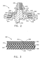
- FIG 3 is a cross-sectional view of a bearing element 300.
- Bearing element 300 may be utilized, for example, in a variable vane assembly, such as variable vane assembly 200, (shown in Figure 2), as washer 220 and/or seal 204.
- bearing element 300 may be used in any bearing assembly where it is desirable to have durability and a low coefficient of friction.
- Bearing element 300 includes a first layer 302, a second layer 304, and a third layer 306.
- Second layer 304 includes a first side 308 and a second side 310.
- First layer 302 includes an interior surface 312 and an exterior surface 314.
- third layer 306 includes an interior surface 316 and an exterior surface 318.
- First layer 302 and third layer 306 are fabricated from Teflon fibers and glass fibers woven into the form of a mat.
- Second layer 304 is fabricated from glass fibers which are also woven into the form of a mat.
- the Teflon and glass fibers utilized in the fabrication of first layer 302 and third layer 306 are woven such that exterior surfaces 314 and 318 include mostly Teflon fibers while interior surfaces 312 and 316 include mostly glass fibers.
- the Teflon fibers on exterior surfaces 314 and 318 enhance the low coefficient of friction of bearing component 300 and the glass fibers on interior surfaces 312 and 316 allow for better adhesion of first layer 302 and third layer 306 to second layer 304.
- layers 302, 304, and 306 may be braided with first layer 302 and third layer 306 fabricated from Teflon fibers and carbon fibers, and second layer 304 fabricated from carbon fibers.
- First layer 302, second layer 304, and third layer 306 are impregnated with a polyimide resin suitable for enhancing durability and lowering the coefficient of friction of bearing element 300.
- Suitable polyimide resins include NR-150, commercially available from E.I. duPont de Nemours and Company, Wilmington, Delaware, MVK-19, commercially available from Maverick Corporation, Cincinnati, Ohio, Xylan 1010, commercially available from Whitford Corporation, West Chester, Pennsylvania, Skybond-703, commercially available from I.S.T. America, Chula Vista, California, and PMR-15, commercially available from Cytec Industries, Inc., West Paterson, New Jersey.
- bearing element 300 To form bearing element 300, a polyimide resin is impregnated into first layer 302, second layer 304, and third layer 306 and then cured. First layer 310, second layer 312, and third layer 314 are placed in contact with each other and are then bonded together to form bearing component 300.
- Teflon powder may be added to the polyimide resin to provide increased durability and lower the coefficient of friction for bearing component 300.
- a final coating of the polyimide resin containing Teflon powder, MoS 2 particles, or combinations thereof may also be utilized to further enhance the durability and lower the coefficient of friction of bearing component 300.
- first layer 302, second layer 304, and third layer 306 may be plasma etched prior to being impregnated with the polyimide resin to enhance bonding of the resin to bearing component 300.
- first layer 302, second layer 304, and third layer 306 are typically coated with a sizing material, such as an epoxy.
- the sizing material may be replaced with other suitable materials, such as silane.
- the glass fibers utilized to form first layer 310, second layer 312, and third layer 314 may be replaced with quartz fibers.
- the bearing assembly significantly restricts airflow through the stator casing, thus leading to a longer and improved service life for the variable vane assembly. Since air leaks are reduced or prevented through the opening, the turbine engine has an increased efficiency. Further, the overhaul costs of the turbine engine in general, and specifically the compressor, will be reduced since contact between the casing, the variable vane, and the spacer is substantially reduced, or eliminated.
Description
- This invention relates generally to bearing assemblies and, more particularly, to bearing assembly materials such as known from e.g. GB 2 095 170, US 5 162 157, US 5 322 882.
- Gas turbine engines generally include a high pressure compressor, a combustor, and a high pressure turbine. Compressed air flows through the engine while fuel is mixed with the compressed air and ignited to form a high energy gas steam in the high pressure compressor and combustor, respectively. The high pressure compressor, combustor, and high pressure turbine are sometimes collectively referred to as a core engine. Such gas turbine engines also may include a low pressure compressor for supplying compressed air, for further compression, to the high pressure compressor, and a fan for supplying air to the low pressure compressor.
- The high pressure compressor typically includes a rotor surrounded by a casing. The casing is typically fabricated to be removable, such as by forming the casing into two halves that are then removably joined together. The high pressure compressor includes a plurality of stages and each stage includes a row of rotor blades and a row of stator vanes. The casing supports the stator vanes, and the rotor supports the rotor blades. The stator vane rows are between the rotor blade rows and direct air flow toward a downstream rotor blade row.
- Variable stator vane assemblies are utilized to control the amount of air flowing through the compressor to optimize performance of the compressor. Each variable stator vane assembly includes a variable stator vane which extends between adjacent rotor blades. The variable stator vane is rotatable about an axis. The orientation of the variable stator vane affects air flow through the compressor.
- A known variable vane assembly includes a variable vane, a trunnion seal, and a washer. The variable vane assembly is bolted onto a high pressure compressor stator casing and the trunnion seal and washer surround an opening that extends through the casing. The variable vane includes a vane stem that extends through the opening in casing and through the trunnion seal and washer. The seal and washer are referred to herein as a bearing assembly. The bearing assembly produces a low friction surface that prevents metal on metal contact. Such variable vane assemblies have possible air leakage pathways through the openings in the casing. Also, the high velocity and high temperature air causes oxidation and erosion of the bearing assemblies, which may lead to failure of fibers within the bearing assembly, and eventual failure of the variable vane assembly.
- Once the bearing assembly fails, an increase in leakage through the opening occurs, which results in a performance loss. In addition, failure of the bearing assembly allows contact between the stator vane and the casing, which causes wear and increases overhaul costs of the engine.
- Accordingly, it would be desirable to provide bearing assemblies fabricated from materials having performance characteristics that will reduce or eliminate air leakage between the stator vane stem and the compressor casing. In addition, it would be desirable to provide an increase in the durability of the seal and washer composition to increase part life.
- In one embodiment of the invention, the bearing assembly includes a washer and a seal positioned on the casing to surround an opening. The vane stem extends through the opening and the bearing assembly.
Outer layers of each element in the bearing assembly are fabricated from a combination of materials that provide a low coefficient of friction. - The seal prevents the stator vane from contacting the stator casing and prevents air flow from exiting the opening. The washer prevents contact between a spacer and the casing and also prevents air flow from exiting the opening. The bearing assembly thus provides two barriers to air flow escaping through the opening in the stator casing.
- The seal and washer are fabricated from a combination of materials, such as Teflon fibers and glass fibers impregnated with a polyimide resin, that have desirable performance characteristics and that provide a low coefficient of friction. In addition, the bearing assembly materials significantly improve the service life of the stator vane assembly and reduce air leakage through the opening in the stator casing. Further, the bearing assembly provides an efficiency improvement in the turbine engine while reducing overhaul costs caused by metal on metal contact between the stator casing, the stator vane, and the spacer.
- The invention will now be described in greater detail, by way of example, with reference to the drawings, in which:-
- Figure 1 is a schematic view of a portion of a high pressure compressor for a turbine engine;
- Figure 2 is a cross-sectional view of a variable vane assembly including a bearing assembly according to one embodiment of the present invention; and
- Figure 3 is a cross-sectional view of layers of the bearing components shown in Figure 2.
-
- Figure 1 is a schematic view of a section of a
high pressure compressor 100 for a turbine engine (not shown).Compressor 100 includes a plurality ofstages 102, and eachstage 102 includes a row ofrotor blades 104 and a row of variablestator vane assemblies 106.Rotor blades 104 are typically supported byrotor disks 108, and are connected to arotor shaft 110.Rotor shaft 110 is a high pressure shaft that is also connected to a high pressure turbine (not shown).Rotor shaft 110 is surrounded by astator casing 112 that supports variablestator vane assemblies 106. - Each variable
stator vane assembly 106 includes avariable vane 114 and avane stem 116. Vane stem 116 protrudes through an opening 118 incasing 112.Variable vane assemblies 106 further include alever arm 120 extending fromvariable vane 114 that is utilized to rotatevariable vanes 114. The orientation ofvanes 114 relative to the flow path throughcompressor 100 controls air flow therethrough. Somevariable vane assemblies 106 are secured tocasing 112 bybolts 122. - Variable vane assemblies 106 control air flow through
compressor 100. However,variable vane assemblies 106 also provide a potential pathway for air flow to exitcompressor 100, such as throughopenings 118. The loss of air flow throughopenings 118 reduces the efficiency ofcompressor 100. - Figure 2 is a schematic view of a
variable vane assembly 200 according to one embodiment of the present invention.Variable vane assembly 200 includes avariable vane 202. Aseal 204 is positioned onvariable vane 202. Acasing 206 supportsvariable vane 202 and includes a first recessedportion 208, aninner portion 210, and a second recessedportion 212. An opening 214 is formed byinner portion 210. -
Seal 204 includes afirst portion 216 and asecond portion 218. Sealfirst portion 216 is in direct contact with casing first recessedportion 208 and separatesvariable vane 202 fromcasing 206. Sealsecond portion 218 contacts casinginner portion 210 and separatesvariable vane 202 fromcasing 206. In one embodiment, sealfirst portion 216 extends substantially an entire length of casing first recessedportion 208. In addition, sealsecond portion 218 extends substantially an entire length of casing secondrecessed portion 212 and is substantially perpendicular to sealfirst portion 216. Seal 204 preventsvariable vane 202 from directly contactingcasing 206. -
Variable vane assembly 200 further includes awasher 220. In one embodiment,washer 220 is substantially flat and includes aninner diameter surface 222 and anouter diameter surface 224. More specifically,washer 220 includes afirst wall 226, asecond wall 228, and athickness 230 that is substantially constant frominner diameter surface 222 toouter diameter surface 224.Washer 220 is in direct contact with casing second recessedportion 212 and extends substantially an entire length of casing second recessedportion 212. -
Variable vane assembly 200 includes aspacer 232 in contact withwasher 220.Washer 220 prevents contact betweenspacer 232 and casing second recessedportion 212.Spacer 232 includes afirst portion 234 and asecond portion 236. Spacerfirst portion 234contacts washer 220 and has a length substantially equal to a radial length ofwasher 220.Spacer 232 is separated fromseal 204 bywasher 220. In one embodiment,seal 204 andwasher 220 do not contact each other.Washer 220 prevents spacer 232 from contactingcasing 206. -
Variable vane 202 also includes afirst portion 238, a ledge 240 having anouter portion 242, and aspacer seating portion 244. Ledge 240 surrounds avane stem 246.Vane stem 246 and ledge 240 extend through opening 214 incasing 206. Sealsecond portion 218 extends alonginner portion 210 ofcasing 206. Sealsecond portion 218 prevents ledgeouter portion 242 from contacting casinginner portion 210. -
Variable vane assembly 200 also includes alever arm 248 positioned aroundvane stem 246 and contactingspacer 232.Lever arm 248 is utilized to adjust the angle ofvariable vane 202, and thus alter the flow of air through the compressor. - In addition,
variable vane assembly 200 includes asleeve 250 contactinglever arm 248, and alever arm nut 252 contactingsleeve 250.Lever arm nut 252 cooperates withvane stem 246 and maintainsvariable vane assembly 200 in contact withcasing 206. -
Variable vane assembly 200 is assembled by placingseal 204 onvariable vane 202 such thatfirst portion 216 andsecond portion 218 contactvariable vane 202 and are substantially perpendicular.Variable vane 202 and seal 204 extend through opening 214. -
Washer 220 is placed oncasing 206adjacent seal 204.Spacer 232 is positioned onvariable vane 202 andcontacts washer 220.Lever arm 238 is positioned overvane stem 246 and contacts spacer 232.Sleeve 250 is positioned overvane stem 246 andcontacts lever arm 248. Finally,lever arm nut 252 is positioned overvane stem 246 andcontacts sleeve 250. -
Washer 220 and seal 204 form a bearing assembly used invariable vane assembly 200 and may be used, for example, in a high pressure compressor. Of course,washer 220 and seal 204 may be utilized in other environments such as a rotor vane assembly, a low pressure compressor variable vane assembly, a high pressure turbine, or a low pressure turbine. - Figure 3 is a cross-sectional view of a
bearing element 300.Bearing element 300 may be utilized, for example, in a variable vane assembly, such asvariable vane assembly 200, (shown in Figure 2), aswasher 220 and/orseal 204. Of course, bearingelement 300 may be used in any bearing assembly where it is desirable to have durability and a low coefficient of friction. -
Bearing element 300 includes afirst layer 302, asecond layer 304, and athird layer 306.Second layer 304 includes afirst side 308 and asecond side 310.First layer 302 includes aninterior surface 312 and anexterior surface 314. Similarly,third layer 306 includes aninterior surface 316 and anexterior surface 318. -
First layer 302 andthird layer 306 are fabricated from Teflon fibers and glass fibers woven into the form of a mat.Second layer 304 is fabricated from glass fibers which are also woven into the form of a mat. The Teflon and glass fibers utilized in the fabrication offirst layer 302 andthird layer 306 are woven such that exterior surfaces 314 and 318 include mostly Teflon fibers whileinterior surfaces exterior surfaces component 300 and the glass fibers oninterior surfaces first layer 302 andthird layer 306 tosecond layer 304. Alternatively, layers 302, 304, and 306 may be braided withfirst layer 302 andthird layer 306 fabricated from Teflon fibers and carbon fibers, andsecond layer 304 fabricated from carbon fibers. -
First layer 302,second layer 304, andthird layer 306 are impregnated with a polyimide resin suitable for enhancing durability and lowering the coefficient of friction of bearingelement 300. Suitable polyimide resins include NR-150, commercially available from E.I. duPont de Nemours and Company, Wilmington, Delaware, MVK-19, commercially available from Maverick Corporation, Cincinnati, Ohio, Xylan 1010, commercially available from Whitford Corporation, West Chester, Pennsylvania, Skybond-703, commercially available from I.S.T. America, Chula Vista, California, and PMR-15, commercially available from Cytec Industries, Inc., West Paterson, New Jersey. - To form bearing
element 300, a polyimide resin is impregnated intofirst layer 302,second layer 304, andthird layer 306 and then cured.First layer 310,second layer 312, andthird layer 314 are placed in contact with each other and are then bonded together to form bearingcomponent 300. - Additionally, Teflon powder may be added to the polyimide resin to provide increased durability and lower the coefficient of friction for bearing
component 300. A final coating of the polyimide resin containing Teflon powder, MoS2 particles, or combinations thereof may also be utilized to further enhance the durability and lower the coefficient of friction of bearingcomponent 300. Alternatively,first layer 302,second layer 304, andthird layer 306 may be plasma etched prior to being impregnated with the polyimide resin to enhance bonding of the resin to bearingcomponent 300. - The glass fibers utilized to form
first layer 302,second layer 304, andthird layer 306 are typically coated with a sizing material, such as an epoxy. The sizing material may be replaced with other suitable materials, such as silane. Alternatively, the glass fibers utilized to formfirst layer 310,second layer 312, andthird layer 314 may be replaced with quartz fibers. - The bearing assembly significantly restricts airflow through the stator casing, thus leading to a longer and improved service life for the variable vane assembly. Since air leaks are reduced or prevented through the opening, the turbine engine has an increased efficiency. Further, the overhaul costs of the turbine engine in general, and specifically the compressor, will be reduced since contact between the casing, the variable vane, and the spacer is substantially reduced, or eliminated.
Claims (9)
- A bearing element (300) comprising:a plurality of layers (302, 304, 306) at least one of said layers formed from a plurality of materials comprising at least one of Teflon fibers, glass fibers, carbon fibers, and combinations thereof; and characterised in thatat least a Teflon powder resin impregnates said layers.
- A bearing element (300) in accordance with Claim 1 wherein said glass fibers are coated with a sizing material comprising at least one of an epoxy coating, a silane coating, and combinations thereof.
- A bearing element (300) in accordance with Claim 1 or 2 wherein each said layer comprises a woven mat of said plurality of material fibers.
- A bearing element (300) in accordance with Claim 1 or 2 wherein each said layer comprises a braided mat of said plurality of material fibers.
- A bearing element (300) in accordance with claim 2, wherein said plurality of layers are plasma etched.
- A bearing element (300) in accordance with claim 2, wherein said sizing material further comprises Teflon powder.
- A bearing element (300) in accordance with claim 1, further comprising a coating including a polyimide resin comprising at least one of a Teflon powder, MoS2 particles, and combinations thereof.
- A bearing element (300) in accordance with Claim 1 or 2 wherein said plurality of layers further comprises a first layer (302) comprising a woven mat of Teflon fibers and glass fibers, a second layer (304) comprising a woven mat of glass fibers, and a third layer (306) comprising a woven mat of Teflon fibers and glass fibers.
- A bearing element (300) in accordance with any preceding Claim, wherein said bearing element comprises at least one of a washer and a seal.
Applications Claiming Priority (2)
| Application Number | Priority Date | Filing Date | Title |
|---|---|---|---|
| US239639 | 1994-05-06 | ||
| US09/239,639 US6264369B1 (en) | 1999-01-29 | 1999-01-29 | Variable vane seal and washer materials |
Publications (3)
| Publication Number | Publication Date |
|---|---|
| EP1024252A2 EP1024252A2 (en) | 2000-08-02 |
| EP1024252A3 EP1024252A3 (en) | 2001-12-12 |
| EP1024252B1 true EP1024252B1 (en) | 2005-01-12 |
Family
ID=22903062
Family Applications (1)
| Application Number | Title | Priority Date | Filing Date |
|---|---|---|---|
| EP00300615A Expired - Lifetime EP1024252B1 (en) | 1999-01-29 | 2000-01-27 | Variable vane seal and washer materials |
Country Status (5)
| Country | Link |
|---|---|
| US (2) | US6264369B1 (en) |
| EP (1) | EP1024252B1 (en) |
| JP (1) | JP2000337385A (en) |
| CA (1) | CA2296655C (en) |
| DE (1) | DE60017293T2 (en) |
Families Citing this family (24)
| Publication number | Priority date | Publication date | Assignee | Title |
|---|---|---|---|---|
| US6474941B2 (en) * | 2000-12-08 | 2002-11-05 | General Electric Company | Variable stator vane bushing |
| US6481960B2 (en) | 2001-03-30 | 2002-11-19 | General Electric Co. | Variable gas turbine compressor vane structure with sintered-and-infiltrated bushing and washer bearings |
| ATE353410T1 (en) * | 2003-04-23 | 2007-02-15 | Glacier Garlock Bearings Inc | COMPOSITE BEARINGS |
| US7220098B2 (en) * | 2003-05-27 | 2007-05-22 | General Electric Company | Wear resistant variable stator vane assemblies |
| US7163369B2 (en) * | 2003-05-27 | 2007-01-16 | General Electric Company | Variable stator vane bushings and washers |
| US20060029494A1 (en) * | 2003-05-27 | 2006-02-09 | General Electric Company | High temperature ceramic lubricant |
| US7094022B2 (en) * | 2003-05-27 | 2006-08-22 | General Electric Company | Variable stator vane bushings and washers |
| US7207770B2 (en) * | 2003-05-27 | 2007-04-24 | General Electric Company | Variable stator vane bushings and washers |
| US7273432B2 (en) * | 2004-01-06 | 2007-09-25 | Litens Automotive Gmbh | Belt tensioner |
| US7543992B2 (en) * | 2005-04-28 | 2009-06-09 | General Electric Company | High temperature rod end bearings |
| US7445427B2 (en) * | 2005-12-05 | 2008-11-04 | General Electric Company | Variable stator vane assembly and bushing thereof |
| US8343370B2 (en) * | 2009-02-19 | 2013-01-01 | Federal-Mogul Corporation | Method of fabricating a PTFE seal element and a shaft seal assembly therewith |
| US9938845B2 (en) | 2013-02-26 | 2018-04-10 | Rolls-Royce Corporation | Gas turbine engine vane end devices |
| KR101406161B1 (en) * | 2013-06-27 | 2014-06-12 | 국방과학연구소 | Manufacturing method of the high performance composite material bearing component |
| EP2886206B1 (en) * | 2013-12-19 | 2016-05-18 | AIRBUS HELICOPTERS DEUTSCHLAND GmbH | Method of coating a bushing |
| FR3023880B1 (en) | 2014-07-16 | 2017-05-26 | Hydromecanique & Frottement | AUTOLUBRICATING FRICTION COMPOSITE PIECE |
| EP2977559B1 (en) * | 2014-07-25 | 2017-06-07 | Safran Aero Boosters SA | Axial turbomachine stator and corresponding turbomachine |
| DE102014218319A1 (en) * | 2014-09-12 | 2015-09-24 | Schaeffler Technologies AG & Co. KG | Sliding bearing component and bearing arrangement with this |
| DE102014218322A1 (en) * | 2014-09-12 | 2015-12-17 | Schaeffler Technologies AG & Co. KG | Sliding bearing component and bearing arrangement with this |
| DE102014224306A1 (en) * | 2014-11-27 | 2016-06-02 | Aktiebolaget Skf | Component comprising at least one sliding layer |
| DE102014224304B4 (en) * | 2014-11-27 | 2020-10-29 | Aktiebolaget Skf | Component comprising at least one sliding layer |
| DE102018108665A1 (en) * | 2018-04-12 | 2019-10-17 | Eisenmann Se | Fan system, air system and system for the treatment of workpieces |
| US11065825B2 (en) * | 2018-12-05 | 2021-07-20 | Raytheon Technologies Corporation | High temperature composite seal |
| US11719111B1 (en) * | 2022-06-29 | 2023-08-08 | Pratt & Whitney Canada Corp. | Variable guide vane system |
Family Cites Families (39)
| Publication number | Priority date | Publication date | Assignee | Title |
|---|---|---|---|---|
| US2809130A (en) * | 1956-05-18 | 1957-10-08 | Gen Motors Corp | Method of bonding a fluorinated synthetic resin to another material |
| US3303992A (en) | 1965-03-03 | 1967-02-14 | Gen Motors Corp | Variable vane stator ring |
| US3318513A (en) * | 1965-03-03 | 1967-05-09 | Gen Motors Corp | Variable vane ring |
| US3582166A (en) * | 1969-06-06 | 1971-06-01 | Lear Siegler Inc | Bearing having low-friction fibrous surface and method for making same |
| US3832255A (en) * | 1970-01-09 | 1974-08-27 | S Shobert | Method of fabricating an improved plastic bearing |
| US3781205A (en) * | 1970-02-02 | 1973-12-25 | Garlock Inc | Composite bearings |
| US3829324A (en) * | 1970-03-31 | 1974-08-13 | Canadian Patents Dev | Bonding condensation polymers to polymeric base materials |
| FR2168662A5 (en) * | 1972-01-19 | 1973-08-31 | Skf Cie Applic Mecanique | |
| US3865665A (en) * | 1972-02-04 | 1975-02-11 | George J Marion | Method of producing multi-layer flat film |
| US3873168A (en) * | 1972-12-18 | 1975-03-25 | Gen Electric | Laminated composite article with improved bearing portion |
| US3909087A (en) * | 1973-01-17 | 1975-09-30 | Garlock Inc | Composite bearings |
| US4111499A (en) * | 1975-03-31 | 1978-09-05 | The Heim Universal Corporation | Bearing assembly and liner |
| US4123122A (en) * | 1976-07-06 | 1978-10-31 | The Torrington Company | Bearing element |
| US5646076A (en) * | 1979-12-21 | 1997-07-08 | Bortz; David N. | Friction controlling devices and methods of their manufacture |
| US4342679A (en) * | 1980-08-27 | 1982-08-03 | Millipore Corporation | Wear-resistant sintered composition having an empirical formula CF1.3 comprising graphite fibers, fluonnated graphite, and PTFE |
| GB2095170A (en) * | 1981-03-16 | 1982-09-29 | Gen Electric | Fibrous bearing material |
| US4394467A (en) * | 1981-06-22 | 1983-07-19 | Celanese Corporation | Sized carbon fibers capable of use with polyimide matrix |
| JPS60141743A (en) * | 1983-12-28 | 1985-07-26 | Uchiyama Mfg Corp | Material composition for bearing sealant |
| DE3481290D1 (en) * | 1984-01-09 | 1990-03-15 | Boeing Co | COMPOSITE MATERIAL STRUCTURE WITH FULL FIRE PROTECTION. |
| JPS61266451A (en) * | 1985-05-21 | 1986-11-26 | Daido Metal Kogyo Kk | Composition for sliding member |
| US4983240A (en) * | 1987-09-11 | 1991-01-08 | Kamatics Corporation | Method of making a flanged braided bearing |
| DE3888265T2 (en) * | 1987-09-11 | 1994-06-16 | Kamatics Corp | Braided bearing and manufacturing method for a braided bearing. |
| JPH068386B2 (en) * | 1988-12-26 | 1994-02-02 | 出光石油化学株式会社 | Polycarbonate resin composition |
| FR2646467A1 (en) | 1989-04-26 | 1990-11-02 | Snecma | STATOR VARIABLE STATOR VANE WITH REPLACED CUP |
| JPH0735514B2 (en) * | 1990-02-27 | 1995-04-19 | 大同メタル工業株式会社 | Sliding member and manufacturing method thereof |
| US5300366A (en) * | 1990-05-09 | 1994-04-05 | Oiles Corporation | Fluororesin composition for a sliding member and a sliding member |
| US5304032A (en) * | 1991-07-22 | 1994-04-19 | Bosna Alexander A | Abradable non-metallic seal for rotating turbine engines |
| US5219232A (en) * | 1991-11-27 | 1993-06-15 | Tiodize Company, Inc. | Floating bushing roller bearing |
| CA2082709A1 (en) | 1991-12-02 | 1993-06-03 | Srinivasan Venkatasubbu | Variable stator vane assembly for an axial flow compressor of a gas turbine engine |
| JPH0823033B2 (en) * | 1992-01-17 | 1996-03-06 | 大同メタル工業株式会社 | Composite sliding member |
| US5281087A (en) | 1992-06-10 | 1994-01-25 | General Electric Company | Industrial gas turbine engine with dual panel variable vane assembly |
| JPH07238270A (en) * | 1994-02-25 | 1995-09-12 | Asahi Glass Co Ltd | Method for bonding fluororesin |
| JP2739452B2 (en) * | 1995-06-28 | 1998-04-15 | 重雄 高橋 | Assembled linear bearing and method of assembling the same |
| US5593275A (en) | 1995-08-01 | 1997-01-14 | General Electric Company | Variable stator vane mounting and vane actuation system for an axial flow compressor of a gas turbine engine |
| US5622473A (en) | 1995-11-17 | 1997-04-22 | General Electric Company | Variable stator vane assembly |
| JP3045472B2 (en) * | 1996-05-31 | 2000-05-29 | 大同メタル工業株式会社 | Sliding member for thrust bearing |
| US5695197A (en) * | 1996-12-06 | 1997-12-09 | Farley; Michael L. | Seal ring method of sealing and molding composition comprising blend of PTFE copolymer, polyamide and carbon fiber therefor |
| GB9713079D0 (en) * | 1997-06-21 | 1997-08-27 | T & N Technology Ltd | Manufacture of plain bearings |
| DE19808541C1 (en) * | 1998-02-28 | 1999-12-02 | Federal Mogul Wiesbaden Gmbh | Layered composite |
-
1999
- 1999-01-29 US US09/239,639 patent/US6264369B1/en not_active Expired - Lifetime
-
2000
- 2000-01-20 CA CA002296655A patent/CA2296655C/en not_active Expired - Fee Related
- 2000-01-27 DE DE60017293T patent/DE60017293T2/en not_active Expired - Fee Related
- 2000-01-27 EP EP00300615A patent/EP1024252B1/en not_active Expired - Lifetime
- 2000-01-28 JP JP2000019612A patent/JP2000337385A/en not_active Withdrawn
-
2001
- 2001-03-29 US US09/821,570 patent/US6915574B2/en not_active Expired - Fee Related
Also Published As
| Publication number | Publication date |
|---|---|
| CA2296655A1 (en) | 2000-07-29 |
| US6915574B2 (en) | 2005-07-12 |
| JP2000337385A (en) | 2000-12-05 |
| EP1024252A3 (en) | 2001-12-12 |
| EP1024252A2 (en) | 2000-08-02 |
| US20010016091A1 (en) | 2001-08-23 |
| DE60017293D1 (en) | 2005-02-17 |
| CA2296655C (en) | 2006-12-05 |
| US6264369B1 (en) | 2001-07-24 |
| DE60017293T2 (en) | 2005-12-22 |
Similar Documents
| Publication | Publication Date | Title |
|---|---|---|
| EP1024252B1 (en) | Variable vane seal and washer materials | |
| US6474941B2 (en) | Variable stator vane bushing | |
| US6146093A (en) | Variable vane seal and washer | |
| EP1400659B1 (en) | Methods and apparatus for sealing gas turbine engine variable vane assemblies | |
| US6808364B2 (en) | Methods and apparatus for sealing gas turbine engine variable vane assemblies | |
| US7094022B2 (en) | Variable stator vane bushings and washers | |
| US6887035B2 (en) | Tribologically improved design for variable stator vanes | |
| US6210106B1 (en) | Seal apparatus for gas turbine engine variable vane | |
| EP1672179B1 (en) | Wear resistant variable stator vane assemblies | |
| US6170990B1 (en) | Trunnion bushing | |
| US9121302B2 (en) | Radial compressor blade clearance control system | |
| CN1978870A (en) | Improved bladed stator for a turbo-engine | |
| US7121727B2 (en) | Inlet guide vane bushing having extended life expectancy | |
| US5435693A (en) | Pin and roller attachment system for ceramic blades | |
| JP3764168B2 (en) | Abrasion resistant air seal assembly for gas turbine engines | |
| US11788424B2 (en) | Sealing ring for a wheel of a turbomachine turbine | |
| US20220213808A1 (en) | Module of an aircraft turbine engine | |
| MXPA99011794A (en) | Variable vane seal and washer |
Legal Events
| Date | Code | Title | Description |
|---|---|---|---|
| PUAI | Public reference made under article 153(3) epc to a published international application that has entered the european phase |
Free format text: ORIGINAL CODE: 0009012 |
|
| AK | Designated contracting states |
Kind code of ref document: A2 Designated state(s): DE FR GB IT Kind code of ref document: A2 Designated state(s): AT BE CH CY DE DK ES FI FR GB GR IE IT LI LU MC NL PT SE |
|
| AX | Request for extension of the european patent |
Free format text: AL;LT;LV;MK;RO;SI |
|
| RIN1 | Information on inventor provided before grant (corrected) |
Inventor name: HESTER, DAVID BARKLEY Inventor name: MESING, THOMAS CARL Inventor name: BOWEN, WAYNE RAY |
|
| PUAL | Search report despatched |
Free format text: ORIGINAL CODE: 0009013 |
|
| RIC1 | Information provided on ipc code assigned before grant |
Free format text: 7F 01D 17/14 A, 7F 04D 29/26 B, 7B 32B 5/28 B |
|
| AK | Designated contracting states |
Kind code of ref document: A3 Designated state(s): AT BE CH CY DE DK ES FI FR GB GR IE IT LI LU MC NL PT SE |
|
| AX | Request for extension of the european patent |
Free format text: AL;LT;LV;MK;RO;SI |
|
| 17P | Request for examination filed |
Effective date: 20020612 |
|
| AKX | Designation fees paid |
Free format text: DE FR GB IT |
|
| 17Q | First examination report despatched |
Effective date: 20021114 |
|
| GRAP | Despatch of communication of intention to grant a patent |
Free format text: ORIGINAL CODE: EPIDOSNIGR1 |
|
| GRAS | Grant fee paid |
Free format text: ORIGINAL CODE: EPIDOSNIGR3 |
|
| GRAA | (expected) grant |
Free format text: ORIGINAL CODE: 0009210 |
|
| AK | Designated contracting states |
Kind code of ref document: B1 Designated state(s): DE FR GB IT |
|
| REG | Reference to a national code |
Ref country code: GB Ref legal event code: FG4D |
|
| REF | Corresponds to: |
Ref document number: 60017293 Country of ref document: DE Date of ref document: 20050217 Kind code of ref document: P |
|
| REG | Reference to a national code |
Ref country code: IE Ref legal event code: FG4D |
|
| ET | Fr: translation filed | ||
| PLBE | No opposition filed within time limit |
Free format text: ORIGINAL CODE: 0009261 |
|
| STAA | Information on the status of an ep patent application or granted ep patent |
Free format text: STATUS: NO OPPOSITION FILED WITHIN TIME LIMIT |
|
| 26N | No opposition filed |
Effective date: 20051013 |
|
| PGFP | Annual fee paid to national office [announced via postgrant information from national office to epo] |
Ref country code: GB Payment date: 20080129 Year of fee payment: 9 Ref country code: IT Payment date: 20080128 Year of fee payment: 9 |
|
| PGFP | Annual fee paid to national office [announced via postgrant information from national office to epo] |
Ref country code: DE Payment date: 20080229 Year of fee payment: 9 Ref country code: FR Payment date: 20080117 Year of fee payment: 9 |
|
| GBPC | Gb: european patent ceased through non-payment of renewal fee |
Effective date: 20090127 |
|
| PG25 | Lapsed in a contracting state [announced via postgrant information from national office to epo] |
Ref country code: DE Free format text: LAPSE BECAUSE OF NON-PAYMENT OF DUE FEES Effective date: 20090801 |
|
| REG | Reference to a national code |
Ref country code: FR Ref legal event code: ST Effective date: 20091030 |
|
| PG25 | Lapsed in a contracting state [announced via postgrant information from national office to epo] |
Ref country code: GB Free format text: LAPSE BECAUSE OF NON-PAYMENT OF DUE FEES Effective date: 20090127 |
|
| PG25 | Lapsed in a contracting state [announced via postgrant information from national office to epo] |
Ref country code: FR Free format text: LAPSE BECAUSE OF NON-PAYMENT OF DUE FEES Effective date: 20090202 |
|
| PG25 | Lapsed in a contracting state [announced via postgrant information from national office to epo] |
Ref country code: IT Free format text: LAPSE BECAUSE OF NON-PAYMENT OF DUE FEES Effective date: 20090127 |