EP1213407A1 - Système de plancher - Google Patents
Système de plancher Download PDFInfo
- Publication number
- EP1213407A1 EP1213407A1 EP00670011A EP00670011A EP1213407A1 EP 1213407 A1 EP1213407 A1 EP 1213407A1 EP 00670011 A EP00670011 A EP 00670011A EP 00670011 A EP00670011 A EP 00670011A EP 1213407 A1 EP1213407 A1 EP 1213407A1
- Authority
- EP
- European Patent Office
- Prior art keywords
- flooring
- tongue
- angle
- recess
- top surface
- Prior art date
- Legal status (The legal status is an assumption and is not a legal conclusion. Google has not performed a legal analysis and makes no representation as to the accuracy of the status listed.)
- Granted
Links
Images


Classifications
-
- E—FIXED CONSTRUCTIONS
- E04—BUILDING
- E04F—FINISHING WORK ON BUILDINGS, e.g. STAIRS, FLOORS
- E04F15/00—Flooring
- E04F15/02—Flooring or floor layers composed of a number of similar elements
- E04F15/04—Flooring or floor layers composed of a number of similar elements only of wood or with a top layer of wood, e.g. with wooden or metal connecting members
-
- E—FIXED CONSTRUCTIONS
- E04—BUILDING
- E04F—FINISHING WORK ON BUILDINGS, e.g. STAIRS, FLOORS
- E04F2201/00—Joining sheets or plates or panels
- E04F2201/01—Joining sheets, plates or panels with edges in abutting relationship
- E04F2201/0107—Joining sheets, plates or panels with edges in abutting relationship by moving the sheets, plates or panels substantially in their own plane, perpendicular to the abutting edges
- E04F2201/0115—Joining sheets, plates or panels with edges in abutting relationship by moving the sheets, plates or panels substantially in their own plane, perpendicular to the abutting edges with snap action of the edge connectors
Definitions
- the invention generally relates to flooring panels. More specifically, the invention is directed to flooring panels which are maintained in position relative to each other by the use of tongue and groove technology.
- Patent EP 813641 relates to a floor or wall panel and the use thereof in a humid compartment.
- the panel is equipped with locking means in the form of a groove and a tongue which form a union between the groove and the tongue suitable for fitting the panels together.
- the groove and the tongue are made of a waterproof material and they are formed with an quick engagement coupling element, which is under pressure and has the effect of a spring.
- Patent EP 843763 relates to a floor covering consisting of wooden floor panels, said hard floor panels having, at least along the edges of two opposite sides, coupling parts which are formed in such a way as to constitute a single part together with said wooden central component, and they cooperate with each other, substantially in the form of a tongue and a groove. It is essentially characterised in that the coupling elements are fitted with mechanical locking means which prevent the two flooring panels from moving apart in a direction perpendicular to the associated edges and parallel to the lower side of said coupled panels.
- the invention is directed to a flooring system made of flooring panels.
- a first flooring panel or member has a first top surface and a first engagement portion.
- a second flooring member has a second top surface which is essentially parallel to the first top surface, and a second engagement portion.
- the first engagement portion can be an elongated tongue with a locking projection extending therefrom.
- the locking projection has a first inclined surface which is inclined at a first angle relative to the first top surface.
- the second engagement portion can be in the form of an elongated recess with a locking cavity extending therefrom.
- the locking cavity has a second inclined surface which is inclined at a second angle relative to the first top surface. The second angle is larger than the first angle.
- the configuration of the flooring panels insures that the top or upper surfaces of the panels will be positioned in the same plane, adding significantly to the aesthetic and functional nature of the floor. Also the cooperation of the panels insures that the panels will fit together properly and prevents the separation of the panels from each other, thereby eliminating inappropriate spaces between panels.
- the cost of tooling to produce the flooring panels is minimised.
- the tooling does not need to be reconditioned as often, thereby eliminating costly downtime for the tooling.
- FIG 1 illustrates a flooring system according to the invention.
- Each flooring panel 10 has a first major surface 12 and an oppositely facing second major surface 14. Side surfaces 16, 18 and end surfaces 20, 22 extend between the major surface 12 and 14. Although the flooring panels 10 are shown as rectangular, other types of configurations are possible.
- the first major surface 12 has a laminate or thin layer 24 of decorative wood provided thereon and is designed to face away from the subfloor, as shown in Figure 1.
- the core 26 of each flooring panel 10 is made from material which has the strength, absorption, and other characteristics required. As the core will not be exposed once the flooring system is completely installed, the core 26 must not be as physically appealing as the layer 24.
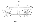
- side surface 16 has a laminate portion 30 which extends from the first major surface 12 in a direction essentially perpendicular to the first major surface.
- a raduised portion 32 is provided proximate the laminate portion 30. The raduised portion extends inward toward side surface 18 from the plan of laminate portion 30.
- a tongue 40 extends from side surface 16 outward in a direction away from side surface 18. The tongue is positioned below the raduised portion 32 when viewed in Figure 4.
- a bottom straight portion 34 and bottom angled position 36 also are provided on the side surface 16. The portions 34 and 36 are offset toward side surface 16 from the plan of laminate portion 30.
- tongue 40 has a fixed end 42 attached to side surface 16 and a free end 44 which has a rounded or arcuate configuration.
- An upper surface 46 and a lower surface 48 extend between the free end and the fixed end. In the embodiment shown, the planes of the upper and lower surfaces are essentially parallel to the plan of the first major surface 12.
- a projection 50 extends from the lower surface 48.
- the projection has a first inclined surface 52 and a second inclined surface 54.
- the first inclined surface 52 is inclined at an angle A from a line which is perpendicular to the plane of the first major surface 12.
- the second inclined surface 54 is inclined at an angle B from a line which is perpendicular to the plane of the first major surface 12. In the embodiment shown, the angle A is 70° and the angle B is 45°. However, the angles can be varied and still fall within the scope of the invention.
- Side surface 18 has a laminate portion 60 which extends from the first major surface 12 in a direction essentially perpendicular to the first major surface and essentially parallel to the laminate portion 30.
- a lead-in portion 62 is provided proximate laminate portion 60. The lead-in portion 62 slopes inward toward side surface 16.
- a recess 70 extends from side surface 18 inward in a direction toward side surface 16. The recess 70 is provided below the lead-in portion 62 when viewed in Figure 4.
- a raduised portion 64 and bottom angled portion 66 are provided on the side surface 18. The portions 64 and 66 are offset toward side surface 16 from the plane of laminate portion 60.
- Recess 70 has open end 72 and a closed end 74.
- An upper surface 76 and a lower surface 78 extend between the open end and closed end.
- the planes of the upper and lower surfaces 76, 78 are essentially parallel to the plane of the first major surface 12.
- the space X between the upper surface 76 and lower surface 78 is dimensioned to be larger than the dimension Y between the upper surface 46 and lower surface 48 of the tongue 40.
- a channel 80 is provided in the lower surface 78 and extends from the lower surface in a direction toward the second major surface 14.
- the channel 80 has a first inclined surface 82 and a second inclined surface 84.
- the first inclined surface 82 is inclined at an angle C from a line which is perpendicular to the plane of the first major surface 12.
- the second inclined surface 84 is inclined at an angle D from a line which is perpendicular to the plane of the first major surface 12.
- the angle C is 65° and the angle D is 45°.
- the angles can be varied and still fall within the scope of the invention.
- individual flooring panels 10 are joined together to form a flooring system.
- various individual flooring panels 10 are positioned on the subfloor and manipulated into engagement with other flooring panels 10'. This process is best illustrated in Figures 1 and 2.
- a respective flooring panel 10 is laid on subfloor 90, such that the second major surface 14 is in contact with and essentially parallel to the subfloor 90.
- the flooring panel 10 is moved in the direction of the arrows until such time when the tongue 40' of flooring panel 10' engages a portion of recess 70 of flooring panel 10.
- channel 80 cooperates with projection 50'.
- first inclined surface 52' of projection 50 cooperates with the first inclined surface 82 of channel 80 and the second inclined surface 54' of projection 50' either cooperates with or is in close proximity to second inclined surface 84 of channel 80.
- first inclined surface 52' and first inclined surface 82 performs an important function with respect to the proper installation of the flooring system.
- first major surfaces 12 of each flooring panel must be aligned and must be in the same plane. Even slight variances in the positioning of the first major surfaces can cause the floor to be unattractive and unsafe. Therefore, it is important to provide the flooring panels with a mechanism to insure that the first major surfaces will be coplanar.
- first inclined surface 52' extends at an angle A from a line perpendicular to the first major surface and the first inclined surface 82 extends at an angle C from a line perpendicular to the first major surface.
- angle A is 70° and angle C is 65°
- the slope of surface 82 is steeper than the slope of surface 52'. Therefore, as flooring panel 10 and flooring 10' are moved together, surface 52' will engage surface 82.
- the continued installation of flooring panels causes 52' to be biased upward.
- surface 52' is biased upward by surface 82 causing upper surface 46' of tongue 40' to engage upper surface 76 of recess 70.
- upper surface 46' is accurately controlled relative to the first major surface 12' as the flooring panel 10' is manufactured.
- upper surface 76 is accurately controlled relative to the first major surface 12 as the flooring panel 10 is manufactured. Consequently, the dimensioning of the flooring panels insures that when surfaces 46' and 76 are provided in engagement, the first major surface 12 will be positioned in the same plane as any other respective first major surface 12'. Therefore, with tongue 40' positioned in recess 70 as described, the coplanarity of the first major surface 12 with first major surface 12' is assured.
- angles described with respect to the preferred embodiment have certain defined values, the scope of the invention is not limited to those specific values. Rather the invention is accomplished if angle A is greater than angle C, thereby causing surface 82 to have a steeper slope than surface 52'.
- angles B and D are identical in the embodiment shown. This insures that surfaces 54' and 84 are essentially parallel to each other. This type of configuration helps to hold surfaces 52' and 82 in position relative to each other. The cooperation of surfaces 54' and 84 helps to maintain surfaces 52' and 82 in engagement, thereby facilitating the coplanarity of surfaces 12 and 12'. The cooperation of surfaces 54' and 84 also prevents the separation of panel 10 from panel 10'.
- the dimensions of angles B and D are not as important as the dimensions of A and C. In fact, in order for the flooring panels to be properly positioned, it is not essential that surfaces 52' and 82 be coplanar.
- the tongue 40' extends from flooring panel 10' and the recess 70 is provided in flooring panel 10.
- the invention operates in the same manner if the recess 70' is provided in the flooring panel 10' and the tongue 40 extends from flooring panel 10.
- the configuration of the flooring panels insures that the upper surfaces 12 of the panels will be positioned in the same plane, adding significantly to the aesthetic and functional nature of the floor. Also, the cooperation of the projection 50 with channel 80 prevents the separation of the panels. If the panels are permitted to separate, the aesthetics of the flooring system is degraded. Separation of the panels can also cause safety and maintenance issues.
- the configuration of the sides and ends of the flooring panels also helps insure that the flooring panels will fit together properly.
- the only other portions of the flooring panels which engage are the portions 30 and 60 which are proximate the surface 12. As no other portions engage, the other portions will not prevent the surfaces 12 of panels from being held in the proper spaced relationship.
- the portions of the panels resiliently deform, causing the tongue to effectively click in place in the recess.
- This positive retention of the tongue in the recess provides sufficient force to retain the flooring panels together, with or without the use of a glue or adhesive. Consequently, the invention can be used with or without glue.
Priority Applications (3)
| Application Number | Priority Date | Filing Date | Title |
|---|---|---|---|
| EP00670011A EP1213407B1 (fr) | 2000-12-06 | 2000-12-06 | Système de plancher |
| DE60029331T DE60029331D1 (de) | 2000-12-06 | 2000-12-06 | Fussbodensystem |
| AT00670011T ATE333018T1 (de) | 2000-12-06 | 2000-12-06 | Fussbodensystem |
Applications Claiming Priority (1)
| Application Number | Priority Date | Filing Date | Title |
|---|---|---|---|
| EP00670011A EP1213407B1 (fr) | 2000-12-06 | 2000-12-06 | Système de plancher |
Publications (2)
| Publication Number | Publication Date |
|---|---|
| EP1213407A1 true EP1213407A1 (fr) | 2002-06-12 |
| EP1213407B1 EP1213407B1 (fr) | 2006-07-12 |
Family
ID=8174496
Family Applications (1)
| Application Number | Title | Priority Date | Filing Date |
|---|---|---|---|
| EP00670011A Expired - Lifetime EP1213407B1 (fr) | 2000-12-06 | 2000-12-06 | Système de plancher |
Country Status (3)
| Country | Link |
|---|---|
| EP (1) | EP1213407B1 (fr) |
| AT (1) | ATE333018T1 (fr) |
| DE (1) | DE60029331D1 (fr) |
Cited By (2)
| Publication number | Priority date | Publication date | Assignee | Title |
|---|---|---|---|---|
| WO2006089467A1 (fr) * | 2005-02-28 | 2006-08-31 | Danyang Leico Diamond Precise Tools Co., Ltd. | Eclisse pour plancher antifissures monte a plat resistant au flambage |
| JP2014500923A (ja) * | 2010-11-23 | 2014-01-16 | アクツェンタ パネーレ ウント プロフィレ ゲゼルシャフト ミット ベシュレンクテル ハフツング | 軟質/弾性摩耗層を有するフロアパネル |
Citations (4)
| Publication number | Priority date | Publication date | Assignee | Title |
|---|---|---|---|---|
| EP0813641A1 (fr) | 1995-03-07 | 1997-12-29 | Perstorp Flooring Ab | Panneau de sol ou mural et son utilisation |
| EP0843763A1 (fr) | 1996-06-11 | 1998-05-27 | Unilin Beheer B.V. | Revetement de sol compose de panneaux de plancher durs et procede de fabrication de ces panneaux de plancher |
| DE20002413U1 (de) * | 1999-12-23 | 2000-04-27 | Hamberger Industriewerke Gmbh | Verbindung |
| FR2785633A1 (fr) * | 1998-11-09 | 2000-05-12 | Valerie Roy | Panneau de recouvrement pour parquet, lambris ou analogue |
-
2000
- 2000-12-06 AT AT00670011T patent/ATE333018T1/de not_active IP Right Cessation
- 2000-12-06 EP EP00670011A patent/EP1213407B1/fr not_active Expired - Lifetime
- 2000-12-06 DE DE60029331T patent/DE60029331D1/de not_active Expired - Lifetime
Patent Citations (4)
| Publication number | Priority date | Publication date | Assignee | Title |
|---|---|---|---|---|
| EP0813641A1 (fr) | 1995-03-07 | 1997-12-29 | Perstorp Flooring Ab | Panneau de sol ou mural et son utilisation |
| EP0843763A1 (fr) | 1996-06-11 | 1998-05-27 | Unilin Beheer B.V. | Revetement de sol compose de panneaux de plancher durs et procede de fabrication de ces panneaux de plancher |
| FR2785633A1 (fr) * | 1998-11-09 | 2000-05-12 | Valerie Roy | Panneau de recouvrement pour parquet, lambris ou analogue |
| DE20002413U1 (de) * | 1999-12-23 | 2000-04-27 | Hamberger Industriewerke Gmbh | Verbindung |
Cited By (2)
| Publication number | Priority date | Publication date | Assignee | Title |
|---|---|---|---|---|
| WO2006089467A1 (fr) * | 2005-02-28 | 2006-08-31 | Danyang Leico Diamond Precise Tools Co., Ltd. | Eclisse pour plancher antifissures monte a plat resistant au flambage |
| JP2014500923A (ja) * | 2010-11-23 | 2014-01-16 | アクツェンタ パネーレ ウント プロフィレ ゲゼルシャフト ミット ベシュレンクテル ハフツング | 軟質/弾性摩耗層を有するフロアパネル |
Also Published As
| Publication number | Publication date |
|---|---|
| ATE333018T1 (de) | 2006-08-15 |
| EP1213407B1 (fr) | 2006-07-12 |
| DE60029331D1 (de) | 2006-08-24 |
Similar Documents
| Publication | Publication Date | Title |
|---|---|---|
| EP1626136B2 (fr) | Système de plancher comprenant des planches de plancher avec un système de verrouillage des bords courts | |
| US20020059765A1 (en) | Flooring product | |
| EP2009195B1 (fr) | Matériau de plancher comprenant des éléments de plancher sous forme de planches joints par des éléments de liaison | |
| US8484924B2 (en) | Panel, in particular floor panel | |
| EP2041380B1 (fr) | Système de verrouillage comprenant un verrou à combinaison pour panneaux | |
| EP1084317B1 (fr) | Systeme de blocage et planches de parquet | |
| CA2481393C (fr) | Panneau et systeme de verrouillage pour panneaux | |
| US8381477B2 (en) | Mechanical locking of floor panels with a flexible tongue | |
| US20020178682A1 (en) | System for joining building panels | |
| US20030196405A1 (en) | System for joining building panels | |
| US20080010937A1 (en) | Locking system comprising a combination lock for panels | |
| EP1213407B1 (fr) | Système de plancher | |
| BE1028044A1 (nl) | Wand- of plafondpaneel en wand- of plafondbekleding | |
| EP1516977A1 (fr) | Panneau, en particulier pour parquets | |
| EP2813637A2 (fr) | Matériau de plancher comprenant des éléments de plancher joints par des éléments de liaison. |
Legal Events
| Date | Code | Title | Description |
|---|---|---|---|
| PUAI | Public reference made under article 153(3) epc to a published international application that has entered the european phase |
Free format text: ORIGINAL CODE: 0009012 |
|
| AK | Designated contracting states |
Kind code of ref document: A1 Designated state(s): AT BE CH CY DE DK ES FI FR GB GR IE IT LI LU MC NL PT SE TR |
|
| AX | Request for extension of the european patent |
Free format text: AL PAYMENT 20001211;LT PAYMENT 20001211;LV PAYMENT 20001211;MK PAYMENT 20001211;RO PAYMENT 20001211;SI PAYMENT 20001211 |
|
| AKX | Designation fees paid |
Designated state(s): AT BE CH CY DE DK ES FI FR GB GR IE IT LI LU MC NL PT SE TR |
|
| AXX | Extension fees paid |
Extension state: SI Payment date: 20001211 Extension state: AL Payment date: 20001211 Extension state: MK Payment date: 20001211 Extension state: LT Payment date: 20001211 Extension state: RO Payment date: 20001211 Extension state: LV Payment date: 20001211 |
|
| 17P | Request for examination filed |
Effective date: 20021209 |
|
| GRAP | Despatch of communication of intention to grant a patent |
Free format text: ORIGINAL CODE: EPIDOSNIGR1 |
|
| GRAS | Grant fee paid |
Free format text: ORIGINAL CODE: EPIDOSNIGR3 |
|
| GRAA | (expected) grant |
Free format text: ORIGINAL CODE: 0009210 |
|
| AK | Designated contracting states |
Kind code of ref document: B1 Designated state(s): AT BE CH CY DE DK ES FI FR GB GR IE IT LI LU MC NL PT SE TR |
|
| AX | Request for extension of the european patent |
Extension state: AL LT LV MK RO SI |
|
| PG25 | Lapsed in a contracting state [announced via postgrant information from national office to epo] |
Ref country code: IT Free format text: LAPSE BECAUSE OF FAILURE TO SUBMIT A TRANSLATION OF THE DESCRIPTION OR TO PAY THE FEE WITHIN THE PRESCRIBED TIME-LIMIT;WARNING: LAPSES OF ITALIAN PATENTS WITH EFFECTIVE DATE BEFORE 2007 MAY HAVE OCCURRED AT ANY TIME BEFORE 2007. THE CORRECT EFFECTIVE DATE MAY BE DIFFERENT FROM THE ONE RECORDED. Effective date: 20060712 Ref country code: BE Free format text: LAPSE BECAUSE OF FAILURE TO SUBMIT A TRANSLATION OF THE DESCRIPTION OR TO PAY THE FEE WITHIN THE PRESCRIBED TIME-LIMIT Effective date: 20060712 Ref country code: NL Free format text: LAPSE BECAUSE OF FAILURE TO SUBMIT A TRANSLATION OF THE DESCRIPTION OR TO PAY THE FEE WITHIN THE PRESCRIBED TIME-LIMIT Effective date: 20060712 Ref country code: CH Free format text: LAPSE BECAUSE OF FAILURE TO SUBMIT A TRANSLATION OF THE DESCRIPTION OR TO PAY THE FEE WITHIN THE PRESCRIBED TIME-LIMIT Effective date: 20060712 Ref country code: AT Free format text: LAPSE BECAUSE OF FAILURE TO SUBMIT A TRANSLATION OF THE DESCRIPTION OR TO PAY THE FEE WITHIN THE PRESCRIBED TIME-LIMIT Effective date: 20060712 Ref country code: LI Free format text: LAPSE BECAUSE OF FAILURE TO SUBMIT A TRANSLATION OF THE DESCRIPTION OR TO PAY THE FEE WITHIN THE PRESCRIBED TIME-LIMIT Effective date: 20060712 Ref country code: FI Free format text: LAPSE BECAUSE OF FAILURE TO SUBMIT A TRANSLATION OF THE DESCRIPTION OR TO PAY THE FEE WITHIN THE PRESCRIBED TIME-LIMIT Effective date: 20060712 |
|
| REG | Reference to a national code |
Ref country code: GB Ref legal event code: FG4D |
|
| REG | Reference to a national code |
Ref country code: CH Ref legal event code: EP |
|
| REG | Reference to a national code |
Ref country code: IE Ref legal event code: FG4D |
|
| REF | Corresponds to: |
Ref document number: 60029331 Country of ref document: DE Date of ref document: 20060824 Kind code of ref document: P |
|
| PG25 | Lapsed in a contracting state [announced via postgrant information from national office to epo] |
Ref country code: DK Free format text: LAPSE BECAUSE OF FAILURE TO SUBMIT A TRANSLATION OF THE DESCRIPTION OR TO PAY THE FEE WITHIN THE PRESCRIBED TIME-LIMIT Effective date: 20061012 Ref country code: SE Free format text: LAPSE BECAUSE OF FAILURE TO SUBMIT A TRANSLATION OF THE DESCRIPTION OR TO PAY THE FEE WITHIN THE PRESCRIBED TIME-LIMIT Effective date: 20061012 |
|
| PG25 | Lapsed in a contracting state [announced via postgrant information from national office to epo] |
Ref country code: DE Free format text: LAPSE BECAUSE OF FAILURE TO SUBMIT A TRANSLATION OF THE DESCRIPTION OR TO PAY THE FEE WITHIN THE PRESCRIBED TIME-LIMIT Effective date: 20061013 |
|
| PG25 | Lapsed in a contracting state [announced via postgrant information from national office to epo] |
Ref country code: ES Free format text: LAPSE BECAUSE OF FAILURE TO SUBMIT A TRANSLATION OF THE DESCRIPTION OR TO PAY THE FEE WITHIN THE PRESCRIBED TIME-LIMIT Effective date: 20061023 |
|
| PG25 | Lapsed in a contracting state [announced via postgrant information from national office to epo] |
Ref country code: IE Free format text: LAPSE BECAUSE OF NON-PAYMENT OF DUE FEES Effective date: 20061206 |
|
| PG25 | Lapsed in a contracting state [announced via postgrant information from national office to epo] |
Ref country code: PT Free format text: LAPSE BECAUSE OF FAILURE TO SUBMIT A TRANSLATION OF THE DESCRIPTION OR TO PAY THE FEE WITHIN THE PRESCRIBED TIME-LIMIT Effective date: 20061212 |
|
| LTIE | Lt: invalidation of european patent or patent extension |
Effective date: 20060712 |
|
| PG25 | Lapsed in a contracting state [announced via postgrant information from national office to epo] |
Ref country code: MC Free format text: LAPSE BECAUSE OF NON-PAYMENT OF DUE FEES Effective date: 20061231 |
|
| NLV1 | Nl: lapsed or annulled due to failure to fulfill the requirements of art. 29p and 29m of the patents act | ||
| EN | Fr: translation not filed | ||
| PLBE | No opposition filed within time limit |
Free format text: ORIGINAL CODE: 0009261 |
|
| STAA | Information on the status of an ep patent application or granted ep patent |
Free format text: STATUS: NO OPPOSITION FILED WITHIN TIME LIMIT |
|
| 26N | No opposition filed |
Effective date: 20070413 |
|
| GBPC | Gb: european patent ceased through non-payment of renewal fee |
Effective date: 20061206 |
|
| PG25 | Lapsed in a contracting state [announced via postgrant information from national office to epo] |
Ref country code: GB Free format text: LAPSE BECAUSE OF NON-PAYMENT OF DUE FEES Effective date: 20061206 |
|
| PG25 | Lapsed in a contracting state [announced via postgrant information from national office to epo] |
Ref country code: FR Free format text: LAPSE BECAUSE OF FAILURE TO SUBMIT A TRANSLATION OF THE DESCRIPTION OR TO PAY THE FEE WITHIN THE PRESCRIBED TIME-LIMIT Effective date: 20070511 Ref country code: GR Free format text: LAPSE BECAUSE OF FAILURE TO SUBMIT A TRANSLATION OF THE DESCRIPTION OR TO PAY THE FEE WITHIN THE PRESCRIBED TIME-LIMIT Effective date: 20061013 |
|
| PG25 | Lapsed in a contracting state [announced via postgrant information from national office to epo] |
Ref country code: LU Free format text: LAPSE BECAUSE OF NON-PAYMENT OF DUE FEES Effective date: 20061206 Ref country code: TR Free format text: LAPSE BECAUSE OF FAILURE TO SUBMIT A TRANSLATION OF THE DESCRIPTION OR TO PAY THE FEE WITHIN THE PRESCRIBED TIME-LIMIT Effective date: 20060712 |
|
| PG25 | Lapsed in a contracting state [announced via postgrant information from national office to epo] |
Ref country code: CY Free format text: LAPSE BECAUSE OF FAILURE TO SUBMIT A TRANSLATION OF THE DESCRIPTION OR TO PAY THE FEE WITHIN THE PRESCRIBED TIME-LIMIT Effective date: 20060712 Ref country code: FR Free format text: LAPSE BECAUSE OF FAILURE TO SUBMIT A TRANSLATION OF THE DESCRIPTION OR TO PAY THE FEE WITHIN THE PRESCRIBED TIME-LIMIT Effective date: 20060712 |