EP1213241A1 - Feed mechanism for metal cans - Google Patents
Feed mechanism for metal cans Download PDFInfo
- Publication number
- EP1213241A1 EP1213241A1 EP01128180A EP01128180A EP1213241A1 EP 1213241 A1 EP1213241 A1 EP 1213241A1 EP 01128180 A EP01128180 A EP 01128180A EP 01128180 A EP01128180 A EP 01128180A EP 1213241 A1 EP1213241 A1 EP 1213241A1
- Authority
- EP
- European Patent Office
- Prior art keywords
- starwheel
- feed
- infeed
- cans
- feed mechanism
- Prior art date
- Legal status (The legal status is an assumption and is not a legal conclusion. Google has not performed a legal analysis and makes no representation as to the accuracy of the status listed.)
- Withdrawn
Links
Images

Classifications
-
- B—PERFORMING OPERATIONS; TRANSPORTING
- B65—CONVEYING; PACKING; STORING; HANDLING THIN OR FILAMENTARY MATERIAL
- B65G—TRANSPORT OR STORAGE DEVICES, e.g. CONVEYORS FOR LOADING OR TIPPING, SHOP CONVEYOR SYSTEMS OR PNEUMATIC TUBE CONVEYORS
- B65G47/00—Article or material-handling devices associated with conveyors; Methods employing such devices
- B65G47/74—Feeding, transfer, or discharging devices of particular kinds or types
- B65G47/84—Star-shaped wheels or devices having endless travelling belts or chains, the wheels or devices being equipped with article-engaging elements
- B65G47/846—Star-shaped wheels or wheels equipped with article-engaging elements
-
- B—PERFORMING OPERATIONS; TRANSPORTING
- B21—MECHANICAL METAL-WORKING WITHOUT ESSENTIALLY REMOVING MATERIAL; PUNCHING METAL
- B21D—WORKING OR PROCESSING OF SHEET METAL OR METAL TUBES, RODS OR PROFILES WITHOUT ESSENTIALLY REMOVING MATERIAL; PUNCHING METAL
- B21D51/00—Making hollow objects
- B21D51/16—Making hollow objects characterised by the use of the objects
- B21D51/26—Making hollow objects characterised by the use of the objects cans or tins; Closing same in a permanent manner
- B21D51/2692—Manipulating, e.g. feeding and positioning devices; Control systems
-
- B—PERFORMING OPERATIONS; TRANSPORTING
- B65—CONVEYING; PACKING; STORING; HANDLING THIN OR FILAMENTARY MATERIAL
- B65G—TRANSPORT OR STORAGE DEVICES, e.g. CONVEYORS FOR LOADING OR TIPPING, SHOP CONVEYOR SYSTEMS OR PNEUMATIC TUBE CONVEYORS
- B65G47/00—Article or material-handling devices associated with conveyors; Methods employing such devices
- B65G47/02—Devices for feeding articles or materials to conveyors
- B65G47/04—Devices for feeding articles or materials to conveyors for feeding articles
- B65G47/06—Devices for feeding articles or materials to conveyors for feeding articles from a single group of articles arranged in orderly pattern, e.g. workpieces in magazines
- B65G47/08—Devices for feeding articles or materials to conveyors for feeding articles from a single group of articles arranged in orderly pattern, e.g. workpieces in magazines spacing or grouping the articles during feeding
- B65G47/084—Devices for feeding articles or materials to conveyors for feeding articles from a single group of articles arranged in orderly pattern, e.g. workpieces in magazines spacing or grouping the articles during feeding grouping articles in a predetermined 2-dimensional pattern
- B65G47/088—Devices for feeding articles or materials to conveyors for feeding articles from a single group of articles arranged in orderly pattern, e.g. workpieces in magazines spacing or grouping the articles during feeding grouping articles in a predetermined 2-dimensional pattern cylindrical articles
-
- B—PERFORMING OPERATIONS; TRANSPORTING
- B65—CONVEYING; PACKING; STORING; HANDLING THIN OR FILAMENTARY MATERIAL
- B65G—TRANSPORT OR STORAGE DEVICES, e.g. CONVEYORS FOR LOADING OR TIPPING, SHOP CONVEYOR SYSTEMS OR PNEUMATIC TUBE CONVEYORS
- B65G47/00—Article or material-handling devices associated with conveyors; Methods employing such devices
- B65G47/02—Devices for feeding articles or materials to conveyors
- B65G47/04—Devices for feeding articles or materials to conveyors for feeding articles
- B65G47/12—Devices for feeding articles or materials to conveyors for feeding articles from disorderly-arranged article piles or from loose assemblages of articles
- B65G47/14—Devices for feeding articles or materials to conveyors for feeding articles from disorderly-arranged article piles or from loose assemblages of articles arranging or orientating the articles by mechanical or pneumatic means during feeding
- B65G47/1407—Devices for feeding articles or materials to conveyors for feeding articles from disorderly-arranged article piles or from loose assemblages of articles arranging or orientating the articles by mechanical or pneumatic means during feeding the articles being fed from a container, e.g. a bowl
-
- B—PERFORMING OPERATIONS; TRANSPORTING
- B65—CONVEYING; PACKING; STORING; HANDLING THIN OR FILAMENTARY MATERIAL
- B65G—TRANSPORT OR STORAGE DEVICES, e.g. CONVEYORS FOR LOADING OR TIPPING, SHOP CONVEYOR SYSTEMS OR PNEUMATIC TUBE CONVEYORS
- B65G47/00—Article or material-handling devices associated with conveyors; Methods employing such devices
- B65G47/52—Devices for transferring articles or materials between conveyors i.e. discharging or feeding devices
- B65G47/68—Devices for transferring articles or materials between conveyors i.e. discharging or feeding devices adapted to receive articles arriving in one layer from one conveyor lane and to transfer them in individual layers to more than one conveyor lane or to one broader conveyor lane, or vice versa, e.g. combining the flows of articles conveyed by more than one conveyor
- B65G47/71—Devices for transferring articles or materials between conveyors i.e. discharging or feeding devices adapted to receive articles arriving in one layer from one conveyor lane and to transfer them in individual layers to more than one conveyor lane or to one broader conveyor lane, or vice versa, e.g. combining the flows of articles conveyed by more than one conveyor the articles being discharged or distributed to several distinct separate conveyors or to a broader conveyor lane
Definitions
- the present invention generally relates to container manufacturing machines and, in particular, to feed mechanisms for container manufacturing machines.
- Containers are processed within machines that may perform one or several processes. Attempts by many in the industry have been made to make containers in one machine by combining multiple processes within a single entity defined by discrete separation and transport mechanisms. Differing process requirements, cycle times or progressive geometry changes in the article have prevented this from being achieved.
- Containers have to be transported from one process machine to the next and then, in many cases, presented to the processing element of the machine as a discrete unit.
- speeds of up to 2800 per minute For a typical beer or beverage can having a diameter of 2.60 inches, this translates to a conveying speed of 10 feet per second.
- the cans are typically in contact with each other.
- the cans have to be separated and moved further apart This is because the mechanical process components need space to operate on individual cans.
- Machine designers strive to minimize this space, or pitch, but it is typically in excess of 6.0 inches and may be as large as 8.75 for some machines.
- Cans arriving at a process machine without sufficient pitch may be dented during separation. Dents are bad because they weaken the can. In order to maintain adequate strength for further processing, excess metal has to be used to compensate for the denting. As 65% of the cost of the can is the metal, minimizing dents is important. Separating the cans so that they can be processed in a controlled manner and with no damage has become Increasingly difficult as cans have become thinner and speeds increased. Within the infeed of a machine, cans are accelerated to between 150% and 350% of their delivery speed in a few milliseconds.
- Typical early process machinery for feeding cans used either an indexing process or continuous rotary motions.
- an indexing machine one could use a tick-tock gate or the turret periphery to meter product into the machine feed turret or main process turret from a gravity feed track.
- a tick-took gate or the turret periphery could be used to meter rope, belt, chain, magnetic, air or vacuum feed conveyors.
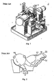
- a conventional gravity feed mechanism for a trimmer is illustrated in Figure 1.
- the Trimmer 1 has two gravity fed infeed chutes 3. Each infeed chute 3 delivers cans directly to a process turret 5. The cans are trimmed and then exit on conveyor 7.
- Continuous rotary motion enabled progressively faster speeds but conventional wisdom held speeds below 100 cpm per working pocket. For a machine to be rated at 800 cpm it needed at least 8 working pockets.
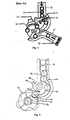
- a preferred separation and timing device used in the prior art was the Feed Screw, illustrated in Figure 2. This was a typically 3" diameter screw 21 with a progressive helix matching the outside diameter of the can.
- the initial lead pitch was the same as the can diameter and the final pitch matched the tangent velocity of the pitch line of the feed turret 23 of the machine.
- the can was fed from the screw 21 into a pocket 22 of feed turret 23.
- the tip 24 of the pocket 22 cupped the can as the can moved toward the main turret 25.
- the can was passed to the main turret 25, trimmed and exited through the discharge chute 27.
- the energy to accelerate and separate the cans comes from gravity or a driving conveyor running under the base of the cans at least as fast as the pitch-line velocity of the turret.
- the screw is used to hold back and meter the cans in a controlled way.
- the Feed Screw was also considered a random feed device.
- a second process machine was operated continuously at a constant speed that was faster than the machine before it. This resulted in gaps in the product flow.
- the first can of the next "stick" (column of cans) was fed at random into the in-running nip of the screw 21 where it sometimes bounced around, getting dented, until there was enough pressure from behind to force it in.
- Other feed techniques used included mechanically complex advancing starwheel pockets or sweeper arms to meter cans to the starwheel.
- Coors introduced a Constant Velocity starwheel on their 1975 LAG 75 Necker/Flanger® , designed for 1200 cpm (Figure 6).
- the 12 pocket turret 63 had a 13.5" pitch can diameter (where the pitch can radius 68 is measured from the center of the turret to the center of the can and the locus of pitch can diameters defines a pitch circle 64). so pocket separation was only 3.5".
- Cans 62 coming in were metered and separated by a combination of a curved infeed track 61 and'a cam form 69 on the trailing side of the hooked starwheel pocket 65.
- the geometry maintained a constant speed of flow in the can stack during the, stripping of each can 62, hence the name.
- In the LAG 75® machines there were no infeed mechanisms at all. Cans 62 fed directly into the main process turret 63.
- a gravity chute 61 linked the process turrets 63 with a timed can stop maintaining the stack height.
- the profile of the pockets has to be truncated at the pitch line 64. This is necessary in order to prevent the tip "hooking" through the can as it is transported away by the subsequent turret. This is illustrated in Figure 6 at numeral 66. Additionally, the hook 65 supports the stack early and does not reverse the flow of the cans 62 (illustrated at numeral 67).
- Belvac used a modified constant velocity (CV) path geometry in trimmers which, by necessity, run at sub-500 cpm speeds.
- the constant velocity infeed starwheel was introduced in 1985 to eliminate a complex tic-toc metering and stop mechanism.
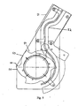
- a CC93® constant velocity infeed is illustrated in Figure 3.
- Cans were gravity fed in the infeed chute 31.
- a pneumatic stop 32 was used to interrupt the flow of the cans into the infeed starwheel 33 as the head was depleted.
- Cans were then passed from the infeed starwheel 33 to the main turret 36 via the infeed gate 35.
- the CC93® infeed also included a timing mechanism 34 to aid in controlling the pneumatic stop. After trimming, the cans entered an outfeed chute 37. Scrap material exited through scrap duct 38.
- the present invention provides a feed mechanism for feeding containers including: an infeed starwheel and a main turret starwheel, wherein the pitch line of the infeed starwheel and the pitch line of the main turret starwheel are non-interfacing.
- the present invention also provides a feed mechanism for feeding containers including: an infeed starwheel, a main turret starwheel and a feed chute with at least one hump for dissipating the head pressure of the incoming can stack.
- the present invention also provides a method of feeding cans to a unit operation in a can making process including; providing a feed chute adapted for gravity feeding said unit operation, the feed chute having a top end and a bottom end, wherein the feed chute has a hump proximal to the bottom end and disposing a plurality of cans in the feed chute, thereby forming a stack of cans in the feed chute.
- Figure 1 is a perspective view of a conventional gravity feed.
- Figure 2 is a schematic view of a conventional screw feed.
- Figure 3 is a schematic view of a conventional constant velocity mechanism.
- Figure 4 is a schematic view of one embodiment of the invention.
- Figure 5 is a schematic view of a second embodiment of the invention.
- Figure 6 is a schematic view of a constant velocity starwheel.
- Figure 7 is a schematic view of a constant velocity starwheel with interfacing pitch circles.
- Figure 4 illustrates one embodiment of the invention.
- This embodiment includes an infeed chute 41, an infeed starwheel 43 disposed at one end of the infeed chute 41, and a main turret 45.
- the infeed starwheel 43 in a preferred embodiment, has three pockets and a first pitch circle 44.
- the infeed starwheel 43 feeds cans into the main turret 45 which has a second pitch circle 46.
- the invention in one embodiment, also includes non-interfacing turret pitches 44, 46.
- Conventional transfer mechanisms transfer cans "pocket to pocket" at the same diametrical pitch.
- the pitch can diameter of the infeed starwheel 43 is less than the pitch can diameter of the main turret 45.
- the smaller initial pitch can diameter 44 substantially reduces the impact energy at the point of separation. In the case of the CC93® , the impact energy is reduced to almost half.
- the can is controlled and moved positively by the pockets, starwheel profiles and guides as it is separated and transferred from one pitch circle 44 to the subsequent one 46.
- non-interfacing pitch circles 44, 46 reduces the impact force compared to the constant velocity starwheel for turret to turret transfers
- the profile of the pocket 49 should also be changed. This new profile almost envelopes the can in a hooked pocket, which provide early support of the stack and cleanly knifes the can away and accelerates it into the pocket.
- the can is extracted from the pocket 49 and rolled onto the tip of the hook by the guide profiles 48 where it is at the correct, identical pitch diameter for a smooth transfer into the subsequent turret.
- This gradual, controlled acceleration through the variable pitch line 47 provides the correct pitch line velocity for transfer to the next turret.
- a second embodiment of the invention includes the use of humps 42 in the infeed chute 41.
- the infeed chute 41 is conventional, Each hump may be sinusoidal or any other shape that produces a smooth perturbation in the chute.
- the size of the hump should be large enough to retard the flow of the incoming can so that the speed is compatible with the speed of the infeed starwheel 43.
- the humps 42 essentially act as a kind of "speed bump", reducing the speed of the can prior to entering the infeed starwheel 43.
- the hump dissipates the head pressure of the incoming can stack, reducing the scuffing tendencies of the rapidly moving starwheel periphery 48 on the can body.
- the preferred embodiment of the "Silent Infeed" of the present invention includes both non-interfacing turret pitches 44, 46 and an integrated tight pitch humped section 42 in the throat of the infeed chute. Both are counter to conventional machinery design practice in the art. However, the inventor has determined that both of these features provide benefits to the process and can be used independently. Furthermore, the invention was illustrated with a three pocket starwheel. However, the invention can be practiced with a starwheel comprising any number of pockets.
- FIG. 5 illustrates another embodiment of the invention.
- the hump 52 is more prominent in the infeed chute 51.
- At the lower end of the infeed chute 51 is a six pocket infeed starwheel 53.
- Each pocket 54 is defined by a leading edge 55 and a cam shaped trailing edge 56. The cam shaped trailing edge aids in developing the proper speed for the transfer to the pocket,
- This invention provides for reduced impact feeding while using existing drive shaft centers and existing shaft gearing ratios. As it is self powered, no extra drive methods are needed and there is no problem of disturbance in a wet or dusty environment,
- This invention can be applied to most can, bottle, case, munitions or other regular object feed systems. It will work at high speeds. Within each stage it will double separations at speeds of 2400 units per minute and treble separation at 1200 without denting fragile cans. If used for caseless ammunition up to 30 mm caliber, it is expected to provide a beltless and linkless rotary feed at speeds up to 4000 rpm.
Landscapes
- Engineering & Computer Science (AREA)
- Mechanical Engineering (AREA)
- Automation & Control Theory (AREA)
- Specific Conveyance Elements (AREA)
Abstract
The present invention provides a feed mechanism for feeding containers.
The feed mechanism includes an infeed starwheel and a main turret starwheel, wherein the
pitch line of the infeed starwheel and the pitch line of the main turret starwheel are noninterfacing.
The present invention also provides a feed mechanism for feeding containers
which includes an infeed starwheel, a main turret starwheel and a feed churc with at least
one hump for dissipating the head pressure of the incoming can stack. The present
invention also provides a method of feeding cans to a unit operation in a can making
process. The method includes the steps of providing a feed chute adapted for gravity
feeding the unit operation, the feed chute having a top end and a bottom end, wherein the
feed chute has at least one hump proximal to the bottom end and disposing a plurality of
cans in the feed chute, thereby forming a stack of cans in the feed chute.
Description
- The present invention generally relates to container manufacturing machines and, in particular, to feed mechanisms for container manufacturing machines.
- Containers are processed within machines that may perform one or several processes. Attempts by many in the industry have been made to make containers in one machine by combining multiple processes within a single entity defined by discrete separation and transport mechanisms. Differing process requirements, cycle times or progressive geometry changes in the article have prevented this from being achieved.
- Containers have to be transported from one process machine to the next and then, in many cases, presented to the processing element of the machine as a discrete unit. In the manufacturing of two piece cans, for example, it is usual to flow containers to the machine in a single file at speeds of up to 2800 per minute. For a typical beer or beverage can having a diameter of 2.60 inches, this translates to a conveying speed of 10 feet per second.
- During transport from process machine to process machine, the cans are typically in contact with each other. However, for processing in the machines, the cans have to be separated and moved further apart This is because the mechanical process components need space to operate on individual cans. Machine designers strive to minimize this space, or pitch, but it is typically in excess of 6.0 inches and may be as large as 8.75 for some machines.
- Cans arriving at a process machine without sufficient pitch, may be dented during separation. Dents are bad because they weaken the can. In order to maintain adequate strength for further processing, excess metal has to be used to compensate for the denting. As 65% of the cost of the can is the metal, minimizing dents is important. Separating the cans so that they can be processed in a controlled manner and with no damage has become Increasingly difficult as cans have become thinner and speeds increased. Within the infeed of a machine, cans are accelerated to between 150% and 350% of their delivery speed in a few milliseconds.
- Typical early process machinery for feeding cans used either an indexing process or continuous rotary motions. For an indexing machine, one could use a tick-tock gate or the turret periphery to meter product into the machine feed turret or main process turret from a gravity feed track. Additionally, a tick-took gate or the turret periphery could be used to meter rope, belt, chain, magnetic, air or vacuum feed conveyors.
- A conventional gravity feed mechanism for a trimmer is illustrated in Figure 1. The Trimmer 1 has two gravity fed
infeed chutes 3. Eachinfeed chute 3 delivers cans directly to a process turret 5. The cans are trimmed and then exit on conveyor 7. - Indexing limited throughput to about 350 cans per minute (cpm) and caused a low feed velocity. Continuous rotary motion enabled progressively faster speeds but conventional wisdom held speeds below 100 cpm per working pocket. For a machine to be rated at 800 cpm it needed at least 8 working pockets.
- A preferred separation and timing device used in the prior art was the Feed Screw, illustrated in Figure 2. This was a typically 3" diameter screw 21 with a progressive helix matching the outside diameter of the can. The initial lead pitch was the same as the can diameter and the final pitch matched the tangent velocity of the pitch line of the
feed turret 23 of the machine. The can was fed from the screw 21 into apocket 22 offeed turret 23. Thetip 24 of thepocket 22 cupped the can as the can moved toward themain turret 25. The can was passed to themain turret 25, trimmed and exited through thedischarge chute 27. The energy to accelerate and separate the cans comes from gravity or a driving conveyor running under the base of the cans at least as fast as the pitch-line velocity of the turret. The screw is used to hold back and meter the cans in a controlled way. - The Feed Screw was also considered a random feed device. A second process machine was operated continuously at a constant speed that was faster than the machine before it. This resulted in gaps in the product flow. The first can of the next "stick" (column of cans) was fed at random into the in-running nip of the screw 21 where it sometimes bounced around, getting dented, until there was enough pressure from behind to force it in. Other feed techniques used included mechanically complex advancing starwheel pockets or sweeper arms to meter cans to the starwheel.
- Coors introduced a Constant Velocity starwheel on their 1975
LAG 75 Necker/Flanger® , designed for 1200 cpm (Figure 6). The 12pocket turret 63 had a 13.5" pitch can diameter (where the pitch canradius 68 is measured from the center of the turret to the center of the can and the locus of pitch can diameters defines a pitch circle 64). so pocket separation was only 3.5".Cans 62 coming in were metered and separated by a combination of a curved infeedtrack 61 and'acam form 69 on the trailing side of the hookedstarwheel pocket 65. The geometry maintained a constant speed of flow in the can stack during the, stripping of each can 62, hence the name. In the LAG 75® machines, there were no infeed mechanisms at all.Cans 62 fed directly into themain process turret 63. Agravity chute 61 linked theprocess turrets 63 with a timed can stop maintaining the stack height. - If the combination of a curved infeed
track 61 and acam form 69 on the trailing side of the hookedstarwheel pocket 65 is used in a direct turret to turret transfer within a machine, the profile of the pockets has to be truncated at thepitch line 64. This is necessary in order to prevent the tip "hooking" through the can as it is transported away by the subsequent turret. This is illustrated in Figure 6 atnumeral 66. Additionally, thehook 65 supports the stack early and does not reverse the flow of the cans 62 (illustrated at numeral 67). - The final evolution of this system was the 595 Super K® (Figure 7). It uses a slightly modified path geometry for 3000 cpm capability feed into a vacuum infeed
turret 73 with 12 pockets and 13.5" pitch can diameter (pitch circle 74). Themain turret 75 also has a 13.5" pitch can diameter (pitch circle 76). Thus, thepitch circles turret 73 has truncated hookedpockets 77 which facilitate transfer of cans from interfacing turrets (illustrated at numeral 79). - Belvac used a modified constant velocity (CV) path geometry in trimmers which, by necessity, run at sub-500 cpm speeds. The constant velocity infeed starwheel was introduced in 1985 to eliminate a complex tic-toc metering and stop mechanism.
- A CC93® constant velocity infeed is illustrated in Figure 3. Cans were gravity fed in the
infeed chute 31. Apneumatic stop 32 was used to interrupt the flow of the cans into theinfeed starwheel 33 as the head was depleted. Cans were then passed from theinfeed starwheel 33 to themain turret 36 via theinfeed gate 35. The CC93® infeed also included atiming mechanism 34 to aid in controlling the pneumatic stop. After trimming, the cans entered anoutfeed chute 37. Scrap material exited throughscrap duct 38. - The present invention provides a feed mechanism for feeding containers including: an infeed starwheel and a main turret starwheel, wherein the pitch line of the infeed starwheel and the pitch line of the main turret starwheel are non-interfacing.
- The present invention also provides a feed mechanism for feeding containers including: an infeed starwheel, a main turret starwheel and a feed chute with at least one hump for dissipating the head pressure of the incoming can stack.
- The present invention also provides a method of feeding cans to a unit operation in a can making process including; providing a feed chute adapted for gravity feeding said unit operation, the feed chute having a top end and a bottom end, wherein the feed chute has a hump proximal to the bottom end and disposing a plurality of cans in the feed chute, thereby forming a stack of cans in the feed chute.
- The foregoing and other features, aspects and advantages of the present invention will become apparent from the following description, appended claims and the exemplary embodiments shown in the drawings. which are briefly described below.
- Figure 1 is a perspective view of a conventional gravity feed.
- Figure 2 is a schematic view of a conventional screw feed.
- Figure 3 is a schematic view of a conventional constant velocity mechanism.
- Figure 4 is a schematic view of one embodiment of the invention.
- Figure 5 is a schematic view of a second embodiment of the invention.
- Figure 6 is a schematic view of a constant velocity starwheel.
- Figure 7 is a schematic view of a constant velocity starwheel with interfacing pitch circles.
- Figure 4 illustrates one embodiment of the invention. This embodiment includes an
infeed chute 41, aninfeed starwheel 43 disposed at one end of theinfeed chute 41, and amain turret 45. Theinfeed starwheel 43, in a preferred embodiment, has three pockets and afirst pitch circle 44. Theinfeed starwheel 43 feeds cans into themain turret 45 which has asecond pitch circle 46. - The invention in one embodiment, also includes non-interfacing turret pitches 44, 46. Conventional transfer mechanisms transfer cans "pocket to pocket" at the same diametrical pitch. However, in a preferable embodiment, the pitch can diameter of the
infeed starwheel 43 is less than the pitch can diameter of themain turret 45. The smaller initial pitch candiameter 44 substantially reduces the impact energy at the point of separation. In the case of the CC93® , the impact energy is reduced to almost half. - In the first embodiment of the invention, it is not necessary to use gravity, air or another means to energize the can and eject it from the metering pocket against a cooperating surface of the pocket of the subsequent turret. The can is controlled and moved positively by the pockets, starwheel profiles and guides as it is separated and transferred from one
pitch circle 44 to thesubsequent one 46. - Although the use of
non-interfacing pitch circles pocket 49 should also be changed. This new profile almost envelopes the can in a hooked pocket, which provide early support of the stack and cleanly knifes the can away and accelerates it into the pocket. - The can is extracted from the
pocket 49 and rolled onto the tip of the hook by the guide profiles 48 where it is at the correct, identical pitch diameter for a smooth transfer into the subsequent turret. This gradual, controlled acceleration through thevariable pitch line 47 provides the correct pitch line velocity for transfer to the next turret. - A second embodiment of the invention includes the use of
humps 42 in theinfeed chute 41. Above thehumps 42, theinfeed chute 41 is conventional, Each hump may be sinusoidal or any other shape that produces a smooth perturbation in the chute. The size of the hump should be large enough to retard the flow of the incoming can so that the speed is compatible with the speed of theinfeed starwheel 43. Thehumps 42 essentially act as a kind of "speed bump", reducing the speed of the can prior to entering theinfeed starwheel 43. The hump dissipates the head pressure of the incoming can stack, reducing the scuffing tendencies of the rapidly movingstarwheel periphery 48 on the can body. It also reduces the tendency of the stack pressure to distort the flexible cans and force them past the controlling interacting geometries of the starwheel and guide surfaces. The size of the humps are dependent on the anticipated head pressure. Too large a hump will "choke" the infeed and create miss-feeds at the separation point. - The preferred embodiment of the "Silent Infeed" of the present invention includes both non-interfacing turret pitches 44, 46 and an integrated tight pitch humped
section 42 in the throat of the infeed chute. Both are counter to conventional machinery design practice in the art. However, the inventor has determined that both of these features provide benefits to the process and can be used independently. Furthermore, the invention was illustrated with a three pocket starwheel. However, the invention can be practiced with a starwheel comprising any number of pockets. - Figure 5 illustrates another embodiment of the invention. In this embodiment, the
hump 52 is more prominent in the infeed chute 51. At the lower end of the infeed chute 51 is a sixpocket infeed starwheel 53. Eachpocket 54 is defined by a leadingedge 55 and a cam shaped trailingedge 56. The cam shaped trailing edge aids in developing the proper speed for the transfer to the pocket, - This invention provides for reduced impact feeding while using existing drive shaft centers and existing shaft gearing ratios. As it is self powered, no extra drive methods are needed and there is no problem of disturbance in a wet or dusty environment,
- This invention can be applied to most can, bottle, case, munitions or other regular object feed systems. It will work at high speeds. Within each stage it will double separations at speeds of 2400 units per minute and treble separation at 1200 without denting fragile cans. If used for caseless ammunition up to 30 mm caliber, it is expected to provide a beltless and linkless rotary feed at speeds up to 4000 rpm.
- The foregoing description of the invention has been presented for purposes of illustration and description. It is not intended to be exhaustive or to limit the invention to the precise form disclosed, and modifications and variations are possible in light of the above teachings or may be acquired from practice of the invention. The drawings and description were chosen in order to explain the principles of the invention and its practical application. It is intended that the scope of the invention be defined by the claims appended hereto, and their equivalents.
Claims (15)
- A feed mechanism for feeding containers comprising:wherein the pitch diameter of the infeed starwheel and the pitch diameter of the main turret starwheel are non-interfacing.an infeed starwheel having tips; anda main turret starwheel;
- A feed mechanism according to claim 1, wherein said infeed starwheel has a pitch diameter smaller than the pitch diameter of said main turret starwheel.
- A feed mechanism according to claim 1, wherein the tips of the infeed starwheel are hooked.
- A feed mechanism according to claim 1, wherein the infeed starwheel accelerates the can into the main turret starwheel.
- A feed mechanism according to claim 1, further comprising a feed chute with at least one hump in said feed chute for dissipating the head pressure of the incoming can stack.
- A feed mechanism according to claim 1, further comprising a feed chute with at least one hump in said feed chute for dissipating the head pressure of the incoming can stack; and
wherein said infeed starwheel has a pitch diameter smaller than the pitch diameter of said main turret starwheel and the tips of the infeed starwheel are truncated. - A feed mechanism according to claim 1, further comprising a can conveying mechanism selected from the group consisting of rope, belt, chain, air or vacuum.
- A feed mechanism for feeding containers comprising:an infeed starwheel having tips;a main turret starwheel; anda feed chute with at least one hump for dissipating the head pressure of the incoming can stack.
- The feed mechanism of claim 7, wherein the hump is large enough to retard the flow of a container so that the speed of the container is compatible with the speed of the infeed starwheel.
- The feed mechanism of claim 8, wherein the tips of the infeed starwheel are hooked.
- The feed mechanism of claim 9, wherein the pitch diameter of the infeed starwheel is less than the pitch diameter of the main turret starwheel.
- A feed mechanism according to claim 8, further comprising a can conveying mechanism selected from the group consisting of rope, bell, chain, air or vacuum.
- A method of feeding cans to a unit operation in a can making process comprising:providing a feed chute for feeding said unit operation, said feed chute having a top end and a bottom end, wherein said feed chute has at least one hump proximal to said bottom end; anddisposing a plurality of cans in said feed chute, thereby forming a stack of cans in said feed chute.
- The method according to claim 13, wherein the position and shape of the hump results in a single can entering the pocket of a starwheel configured to receive cans exiting the feed chute.
- The method according to claim 13, further comprising conveying the can with a can conveying mechanism selected from the group consisting of gravity, rope, belt, chain, air or vacuum.
Applications Claiming Priority (2)
| Application Number | Priority Date | Filing Date | Title |
|---|---|---|---|
| US723205 | 2000-11-28 | ||
| US09/723,205 US6510938B1 (en) | 2000-11-28 | 2000-11-28 | Soft touch infeed |
Publications (1)
| Publication Number | Publication Date |
|---|---|
| EP1213241A1 true EP1213241A1 (en) | 2002-06-12 |
Family
ID=24905289
Family Applications (1)
| Application Number | Title | Priority Date | Filing Date |
|---|---|---|---|
| EP01128180A Withdrawn EP1213241A1 (en) | 2000-11-28 | 2001-11-27 | Feed mechanism for metal cans |
Country Status (2)
| Country | Link |
|---|---|
| US (1) | US6510938B1 (en) |
| EP (1) | EP1213241A1 (en) |
Cited By (3)
| Publication number | Priority date | Publication date | Assignee | Title |
|---|---|---|---|---|
| WO2010026115A1 (en) * | 2008-09-05 | 2010-03-11 | Crown Packaging Technology, Inc. | Necker infeed |
| ITBO20100167A1 (en) * | 2010-03-17 | 2011-09-18 | Neri S P A | FEEDING SYSTEM FOR ITEMS AT A ROTARY PLATFORM COMPARED TO A VERTICAL AXIS |
| CN102791598A (en) * | 2010-03-15 | 2012-11-21 | 皇冠包装技术公司 | Container manufacture |
Families Citing this family (15)
| Publication number | Priority date | Publication date | Assignee | Title |
|---|---|---|---|---|
| US6661020B2 (en) * | 2001-08-30 | 2003-12-09 | Delaware Capital Formation, Inc. | Servo-shutter mechanism for detecting defects in cans |
| US7229270B2 (en) * | 2003-07-30 | 2007-06-12 | Am Mfg. Co. | Reciprocating head press |
| DE10358976B4 (en) * | 2003-12-16 | 2011-07-07 | Borgwaldt Technik GmbH, 22525 | Device for separating cigarettes |
| US7244659B2 (en) * | 2005-03-10 | 2007-07-17 | Micron Technology, Inc. | Integrated circuits and methods of forming a field effect transistor |
| US7735629B2 (en) * | 2007-11-15 | 2010-06-15 | B&H Manufacturing Company, Inc. | Star wheel system with passive star wheel and method for separating containers being processed |
| US8601843B2 (en) | 2008-04-24 | 2013-12-10 | Crown Packaging Technology, Inc. | High speed necking configuration |
| DE102011085534B4 (en) * | 2011-11-01 | 2013-07-04 | Hauni Maschinenbau Ag | Method and device for separating and placing objects in a material strand of the tobacco processing industry |
| DE102013110099A1 (en) * | 2013-09-13 | 2015-03-19 | Khs Gmbh | A method for forming a container stream, container conveyor for carrying out the method and apparatus for treating containers |
| WO2015076823A1 (en) * | 2013-11-22 | 2015-05-28 | Silgan Containers Llc | Can-making apparatus with trimmer chute |
| US9889460B2 (en) * | 2014-09-11 | 2018-02-13 | Verticon, Llc | Continuous vertical spraying of bodies such as cans |
| PL3117722T3 (en) * | 2015-07-16 | 2018-01-31 | Int Tobacco Machinery Poland Sp Zoo | A transfer disc and its use |
| US10968049B2 (en) | 2018-07-20 | 2021-04-06 | Crown Packaging Technology, Inc. | Can body linear loader assembly |
| CN109290499A (en) * | 2018-11-16 | 2019-02-01 | 福州金锻工业有限公司 | Method and device for heating and removing smoke and sorting for forging blanks |
| US11226186B2 (en) * | 2019-01-17 | 2022-01-18 | CK Manufacturing, LLC | Configurable ammunition packaging apparatus |
| CN112623653B (en) * | 2020-11-10 | 2022-07-08 | 东风汽车有限公司 | Steering mechanism for workpiece conveying |
Citations (5)
| Publication number | Priority date | Publication date | Assignee | Title |
|---|---|---|---|---|
| US2269422A (en) * | 1939-12-30 | 1942-01-13 | Ayars Machine Co | Can delivering mechanism |
| US2388804A (en) * | 1942-12-18 | 1945-11-13 | Angelus Sanitary Can Machinery | Can feed mechanism |
| US2886157A (en) * | 1956-02-28 | 1959-05-12 | Merck & Co Inc | Tablet feed device and process |
| US3231061A (en) * | 1963-12-03 | 1966-01-25 | American Can Co | Can handling and transferring apparatus |
| US4467908A (en) * | 1981-10-17 | 1984-08-28 | Krones Ag Hermann Kronseder Maschinenfabrik | Device for the distribution of upright vessels |
Family Cites Families (41)
| Publication number | Priority date | Publication date | Assignee | Title |
|---|---|---|---|---|
| US1301348A (en) | 1916-01-14 | 1919-04-22 | Franklin F Stetson | Can-feeding device. |
| US1713068A (en) | 1925-07-18 | 1929-05-14 | Thermokept Corp | Can-spacing mechanism |
| US2026811A (en) | 1932-11-02 | 1936-01-07 | American Can Co | Can feeding mechanism |
| US2467679A (en) | 1945-11-15 | 1949-04-19 | Package Machinery Co | Infeed mechanism for article handling machines |
| US2868243A (en) | 1956-12-19 | 1959-01-13 | Crown Cork & Seal Co | Container feeding arrangement |
| US3735629A (en) | 1970-06-11 | 1973-05-29 | Standun | Apparatus for forming one piece metallic can bodies |
| US3664171A (en) | 1970-11-13 | 1972-05-23 | Standun | Stripper for apparatus such as metallic can body formers |
| US3715905A (en) | 1971-04-01 | 1973-02-13 | Standun | Part feed for apparatus such as metallic can body formers |
| US3704619A (en) | 1971-06-14 | 1972-12-05 | Standun | Redraw blankholder positioning mechanism for cup-shaped article formers such as metallic can body formers and the like |
| US3825270A (en) | 1972-05-09 | 1974-07-23 | Standun | Wiper seal for apparatus such as metallic can body formers |
| US3735628A (en) | 1972-05-11 | 1973-05-29 | Standun | Metallic can body strippers and the like |
| US3771345A (en) | 1972-06-08 | 1973-11-13 | Standun | End forming station for metallic can body formers and the like |
| USRE28872E (en) | 1973-04-23 | 1976-06-22 | National Can Corporation | Trimming apparatus for tubular bodies |
| US3871233A (en) | 1973-09-17 | 1975-03-18 | Standun | Fluid pressure monitoring device |
| US3886781A (en) | 1974-06-19 | 1975-06-03 | Standun | Force equalized external stripper for metalworking machines and the like |
| US3972299A (en) | 1975-01-31 | 1976-08-03 | The Stolle Corporation | Can body trimmer |
| US3994251A (en) | 1975-11-13 | 1976-11-30 | American Can Company | Apparatus and method for trimming and deburring the edges of cylindrical metal bodies |
| GB1591158A (en) | 1976-11-09 | 1981-06-17 | Cleamax Ltd | High speed can handling mechanism |
| GB2023039A (en) | 1978-06-13 | 1979-12-28 | Metal Box Co Ltd | Apparatus for operating an hollow workpieces |
| JPS54183087U (en) * | 1978-06-15 | 1979-12-25 | ||
| US4246300A (en) | 1979-02-28 | 1981-01-20 | Reynolds Metals Company | Can transport |
| US4534460A (en) * | 1983-01-14 | 1985-08-13 | Lamb Technicon Corp. | Chain-driven pocket elevator |
| US4664159A (en) | 1984-09-21 | 1987-05-12 | Adolph Coors Company | Can filling system to prevent damage to cans |
| US4596107A (en) | 1984-10-30 | 1986-06-24 | Pfleger Sr Fred W | Reject mechanism for bottle capping machine |
| US4632257A (en) * | 1985-01-07 | 1986-12-30 | Sanden Corporation | Article dispensing mechanism for a vending machine |
| US4625775A (en) | 1985-03-27 | 1986-12-02 | Schaltegger Herbert E | High speed container placement apparatus |
| US4753275A (en) | 1985-03-27 | 1988-06-28 | Schaltegger Herbert E | Method and apparatus for high speed container placement |
| US4721200A (en) | 1986-01-21 | 1988-01-26 | Adolph Coors Company | Can filling system to prevent damage to cans |
| US4693055A (en) | 1986-05-09 | 1987-09-15 | Manville Corporation | Method and apparatus for feeding containers to a carrier sleeve |
| US4823983A (en) * | 1987-10-06 | 1989-04-25 | The Coca-Cola Company | Increased column/selectivity vender |
| US5146818A (en) | 1988-04-13 | 1992-09-15 | H. L. Fisher Mfg. Co., Inc. | Can trimming apparatus |
| US4914990A (en) | 1988-04-13 | 1990-04-10 | H. L. Fisher Mfg. Co., Inc. | Apparatus for trimming flanged cans |
| US4928511A (en) | 1988-12-13 | 1990-05-29 | Sequa Corporation | Rotary cup infeed |
| US5231926A (en) | 1991-10-11 | 1993-08-03 | Sequa Corporation | Apparatus and method for substantially reducing can spacing and speed to match chain pins |
| CH687248A5 (en) | 1991-10-30 | 1996-10-31 | Mitsubishi Heavy Ind Ltd | Dosenzufuehreinrichtung for a seaming machine. |
| JP3356468B2 (en) | 1992-10-09 | 2002-12-16 | 株式会社前川製作所 | Screw rotor |
| EP0648566A1 (en) | 1993-08-16 | 1995-04-19 | Reynolds Metals Company | Improvements to methods and apparatus for trimming can bodies |
| US5501552A (en) * | 1994-04-29 | 1996-03-26 | Goldco Industries, Inc. | Conveying system for unstable articles having a neck ring |
| US5613593A (en) | 1994-11-18 | 1997-03-25 | Owens-Brockway Glass Container Inc. | Container handling starwheel |
| US5772001A (en) | 1996-04-18 | 1998-06-30 | B & H Manufacturing Company, Inc. | Star wheel system |
| US5749631A (en) | 1996-04-30 | 1998-05-12 | Sequa Corporation | Dual can rotating transfer plate to conveyor belt |
-
2000
- 2000-11-28 US US09/723,205 patent/US6510938B1/en not_active Expired - Lifetime
-
2001
- 2001-11-27 EP EP01128180A patent/EP1213241A1/en not_active Withdrawn
Patent Citations (5)
| Publication number | Priority date | Publication date | Assignee | Title |
|---|---|---|---|---|
| US2269422A (en) * | 1939-12-30 | 1942-01-13 | Ayars Machine Co | Can delivering mechanism |
| US2388804A (en) * | 1942-12-18 | 1945-11-13 | Angelus Sanitary Can Machinery | Can feed mechanism |
| US2886157A (en) * | 1956-02-28 | 1959-05-12 | Merck & Co Inc | Tablet feed device and process |
| US3231061A (en) * | 1963-12-03 | 1966-01-25 | American Can Co | Can handling and transferring apparatus |
| US4467908A (en) * | 1981-10-17 | 1984-08-28 | Krones Ag Hermann Kronseder Maschinenfabrik | Device for the distribution of upright vessels |
Cited By (5)
| Publication number | Priority date | Publication date | Assignee | Title |
|---|---|---|---|---|
| WO2010026115A1 (en) * | 2008-09-05 | 2010-03-11 | Crown Packaging Technology, Inc. | Necker infeed |
| CN102791598A (en) * | 2010-03-15 | 2012-11-21 | 皇冠包装技术公司 | Container manufacture |
| ITBO20100167A1 (en) * | 2010-03-17 | 2011-09-18 | Neri S P A | FEEDING SYSTEM FOR ITEMS AT A ROTARY PLATFORM COMPARED TO A VERTICAL AXIS |
| EP2366641A1 (en) * | 2010-03-17 | 2011-09-21 | Neri S.p.A. | A system for transporting articles to a starwheel |
| US8434611B2 (en) | 2010-03-17 | 2013-05-07 | Neri S.P.A. | System for supplying articles to a platform rotating about a vertical axis |
Also Published As
| Publication number | Publication date |
|---|---|
| US6510938B1 (en) | 2003-01-28 |
Similar Documents
| Publication | Publication Date | Title |
|---|---|---|
| US6510938B1 (en) | Soft touch infeed | |
| US4757985A (en) | Device for unstacking flat objects | |
| US4697691A (en) | Apparatus for transferring articles, especially bottles | |
| US4526128A (en) | High-speed indexing feed screw conveyer | |
| US3253384A (en) | Envelope filling apparatus | |
| JP2000508610A (en) | Improved star wheel device | |
| CN104261096B (en) | A kind of shell auto-sequencing pay-off | |
| JPS5839748B2 (en) | Printed product handling equipment | |
| US7494003B2 (en) | Outfeed mechanism for starwheel type glass inspection machine | |
| CN1182031A (en) | Method and unit for forming groups of products | |
| US3192565A (en) | Automatic rim rolling apparatus | |
| JPH03124333A (en) | Molding equipment for parts with curved sides | |
| US3351388A (en) | Mechanism for handling and testing containers | |
| US4023513A (en) | Method and apparatus for transferring cans | |
| US8235374B2 (en) | Insertion apparatus and insertion method | |
| US6273238B1 (en) | Apparatus and method for separating adjacent objects on a conveyor | |
| US4708237A (en) | Process and device for supplying an operation station with a succession of guided articles | |
| US5081732A (en) | Rotary heading machine | |
| US5431038A (en) | Apparatus for feeding a workpiece to a tool | |
| GB2110727A (en) | Aligning and individually delivering spinning cops | |
| JP2008214003A (en) | Flat battery can separation and supply device | |
| JP3428721B2 (en) | Can lid conveyor in can lid forming press line | |
| JPH01310828A (en) | Device and method for automatically mounting clamp | |
| US3529509A (en) | Ammunition handling system for dispensing discrete rounds and gun system embodying same | |
| JPH11513648A (en) | Can lid supply device |
Legal Events
| Date | Code | Title | Description |
|---|---|---|---|
| PUAI | Public reference made under article 153(3) epc to a published international application that has entered the european phase |
Free format text: ORIGINAL CODE: 0009012 |
|
| AK | Designated contracting states |
Kind code of ref document: A1 Designated state(s): AT BE CH CY DE DK ES FI FR GB GR IE IT LI LU MC NL PT SE TR |
|
| AX | Request for extension of the european patent |
Free format text: AL;LT;LV;MK;RO;SI |
|
| 17P | Request for examination filed |
Effective date: 20021107 |
|
| AKX | Designation fees paid |
Designated state(s): DE FR GB |
|
| 17Q | First examination report despatched |
Effective date: 20030122 |
|
| STAA | Information on the status of an ep patent application or granted ep patent |
Free format text: STATUS: THE APPLICATION IS DEEMED TO BE WITHDRAWN |
|
| 18D | Application deemed to be withdrawn |
Effective date: 20050601 |