EP1213156A2 - Vehicle-use bearing apparatus - Google Patents
Vehicle-use bearing apparatus Download PDFInfo
- Publication number
- EP1213156A2 EP1213156A2 EP01127817A EP01127817A EP1213156A2 EP 1213156 A2 EP1213156 A2 EP 1213156A2 EP 01127817 A EP01127817 A EP 01127817A EP 01127817 A EP01127817 A EP 01127817A EP 1213156 A2 EP1213156 A2 EP 1213156A2
- Authority
- EP
- European Patent Office
- Prior art keywords
- vehicle
- weight
- ring member
- outer ring
- hub wheel
- Prior art date
- Legal status (The legal status is an assumption and is not a legal conclusion. Google has not performed a legal analysis and makes no representation as to the accuracy of the status listed.)
- Withdrawn
Links
- 239000000463 material Substances 0.000 claims abstract description 45
- 229910000831 Steel Inorganic materials 0.000 claims abstract description 41
- 239000010959 steel Substances 0.000 claims abstract description 41
- 238000005096 rolling process Methods 0.000 claims abstract description 35
- NINIDFKCEFEMDL-UHFFFAOYSA-N Sulfur Chemical compound [S] NINIDFKCEFEMDL-UHFFFAOYSA-N 0.000 claims abstract description 31
- 229910052717 sulfur Inorganic materials 0.000 claims abstract description 31
- 239000011593 sulfur Substances 0.000 claims abstract description 31
- OKTJSMMVPCPJKN-UHFFFAOYSA-N Carbon Chemical compound [C] OKTJSMMVPCPJKN-UHFFFAOYSA-N 0.000 claims description 26
- 229910052799 carbon Inorganic materials 0.000 claims description 26
- 230000002093 peripheral effect Effects 0.000 claims description 25
- 102200003959 rs11556986 Human genes 0.000 claims description 9
- 102200094897 rs121913558 Human genes 0.000 claims description 9
- 239000002436 steel type Substances 0.000 claims description 7
- CADICXFYUNYKGD-UHFFFAOYSA-N sulfanylidenemanganese Chemical compound [Mn]=S CADICXFYUNYKGD-UHFFFAOYSA-N 0.000 description 9
- 102220259718 rs34120878 Human genes 0.000 description 4
- 229910000851 Alloy steel Inorganic materials 0.000 description 2
- 229910000653 SAE 1095 Inorganic materials 0.000 description 2
- 238000012986 modification Methods 0.000 description 2
- 230000004048 modification Effects 0.000 description 2
- 230000036316 preload Effects 0.000 description 2
- PWHULOQIROXLJO-UHFFFAOYSA-N Manganese Chemical compound [Mn] PWHULOQIROXLJO-UHFFFAOYSA-N 0.000 description 1
- 230000000694 effects Effects 0.000 description 1
- 229910052748 manganese Inorganic materials 0.000 description 1
- 239000011572 manganese Substances 0.000 description 1
- 238000004519 manufacturing process Methods 0.000 description 1
- 238000000034 method Methods 0.000 description 1
- 239000000126 substance Substances 0.000 description 1
Images





Classifications
-
- F—MECHANICAL ENGINEERING; LIGHTING; HEATING; WEAPONS; BLASTING
- F16—ENGINEERING ELEMENTS AND UNITS; GENERAL MEASURES FOR PRODUCING AND MAINTAINING EFFECTIVE FUNCTIONING OF MACHINES OR INSTALLATIONS; THERMAL INSULATION IN GENERAL
- F16C—SHAFTS; FLEXIBLE SHAFTS; ELEMENTS OR CRANKSHAFT MECHANISMS; ROTARY BODIES OTHER THAN GEARING ELEMENTS; BEARINGS
- F16C43/00—Assembling bearings
- F16C43/04—Assembling rolling-contact bearings
-
- B—PERFORMING OPERATIONS; TRANSPORTING
- B60—VEHICLES IN GENERAL
- B60B—VEHICLE WHEELS; CASTORS; AXLES FOR WHEELS OR CASTORS; INCREASING WHEEL ADHESION
- B60B27/00—Hubs
-
- B—PERFORMING OPERATIONS; TRANSPORTING
- B60—VEHICLES IN GENERAL
- B60B—VEHICLE WHEELS; CASTORS; AXLES FOR WHEELS OR CASTORS; INCREASING WHEEL ADHESION
- B60B27/00—Hubs
- B60B27/0078—Hubs characterised by the fixation of bearings
- B60B27/0084—Hubs characterised by the fixation of bearings caulking to fix inner race
-
- C—CHEMISTRY; METALLURGY
- C22—METALLURGY; FERROUS OR NON-FERROUS ALLOYS; TREATMENT OF ALLOYS OR NON-FERROUS METALS
- C22C—ALLOYS
- C22C38/00—Ferrous alloys, e.g. steel alloys
- C22C38/02—Ferrous alloys, e.g. steel alloys containing silicon
-
- C—CHEMISTRY; METALLURGY
- C22—METALLURGY; FERROUS OR NON-FERROUS ALLOYS; TREATMENT OF ALLOYS OR NON-FERROUS METALS
- C22C—ALLOYS
- C22C38/00—Ferrous alloys, e.g. steel alloys
- C22C38/04—Ferrous alloys, e.g. steel alloys containing manganese
-
- C—CHEMISTRY; METALLURGY
- C22—METALLURGY; FERROUS OR NON-FERROUS ALLOYS; TREATMENT OF ALLOYS OR NON-FERROUS METALS
- C22C—ALLOYS
- C22C38/00—Ferrous alloys, e.g. steel alloys
- C22C38/18—Ferrous alloys, e.g. steel alloys containing chromium
-
- F—MECHANICAL ENGINEERING; LIGHTING; HEATING; WEAPONS; BLASTING
- F16—ENGINEERING ELEMENTS AND UNITS; GENERAL MEASURES FOR PRODUCING AND MAINTAINING EFFECTIVE FUNCTIONING OF MACHINES OR INSTALLATIONS; THERMAL INSULATION IN GENERAL
- F16C—SHAFTS; FLEXIBLE SHAFTS; ELEMENTS OR CRANKSHAFT MECHANISMS; ROTARY BODIES OTHER THAN GEARING ELEMENTS; BEARINGS
- F16C19/00—Bearings with rolling contact, for exclusively rotary movement
- F16C19/02—Bearings with rolling contact, for exclusively rotary movement with bearing balls essentially of the same size in one or more circular rows
- F16C19/14—Bearings with rolling contact, for exclusively rotary movement with bearing balls essentially of the same size in one or more circular rows for both radial and axial load
- F16C19/18—Bearings with rolling contact, for exclusively rotary movement with bearing balls essentially of the same size in one or more circular rows for both radial and axial load with two or more rows of balls
- F16C19/181—Bearings with rolling contact, for exclusively rotary movement with bearing balls essentially of the same size in one or more circular rows for both radial and axial load with two or more rows of balls with angular contact
- F16C19/183—Bearings with rolling contact, for exclusively rotary movement with bearing balls essentially of the same size in one or more circular rows for both radial and axial load with two or more rows of balls with angular contact with two rows at opposite angles
- F16C19/184—Bearings with rolling contact, for exclusively rotary movement with bearing balls essentially of the same size in one or more circular rows for both radial and axial load with two or more rows of balls with angular contact with two rows at opposite angles in O-arrangement
-
- F—MECHANICAL ENGINEERING; LIGHTING; HEATING; WEAPONS; BLASTING
- F16—ENGINEERING ELEMENTS AND UNITS; GENERAL MEASURES FOR PRODUCING AND MAINTAINING EFFECTIVE FUNCTIONING OF MACHINES OR INSTALLATIONS; THERMAL INSULATION IN GENERAL
- F16C—SHAFTS; FLEXIBLE SHAFTS; ELEMENTS OR CRANKSHAFT MECHANISMS; ROTARY BODIES OTHER THAN GEARING ELEMENTS; BEARINGS
- F16C35/00—Rigid support of bearing units; Housings, e.g. caps, covers
- F16C35/04—Rigid support of bearing units; Housings, e.g. caps, covers in the case of ball or roller bearings
- F16C35/06—Mounting or dismounting of ball or roller bearings; Fixing them onto shaft or in housing
- F16C35/063—Fixing them on the shaft
-
- F—MECHANICAL ENGINEERING; LIGHTING; HEATING; WEAPONS; BLASTING
- F16—ENGINEERING ELEMENTS AND UNITS; GENERAL MEASURES FOR PRODUCING AND MAINTAINING EFFECTIVE FUNCTIONING OF MACHINES OR INSTALLATIONS; THERMAL INSULATION IN GENERAL
- F16C—SHAFTS; FLEXIBLE SHAFTS; ELEMENTS OR CRANKSHAFT MECHANISMS; ROTARY BODIES OTHER THAN GEARING ELEMENTS; BEARINGS
- F16C2326/00—Articles relating to transporting
- F16C2326/01—Parts of vehicles in general
- F16C2326/02—Wheel hubs or castors
-
- Y—GENERAL TAGGING OF NEW TECHNOLOGICAL DEVELOPMENTS; GENERAL TAGGING OF CROSS-SECTIONAL TECHNOLOGIES SPANNING OVER SEVERAL SECTIONS OF THE IPC; TECHNICAL SUBJECTS COVERED BY FORMER USPC CROSS-REFERENCE ART COLLECTIONS [XRACs] AND DIGESTS
- Y02—TECHNOLOGIES OR APPLICATIONS FOR MITIGATION OR ADAPTATION AGAINST CLIMATE CHANGE
- Y02T—CLIMATE CHANGE MITIGATION TECHNOLOGIES RELATED TO TRANSPORTATION
- Y02T10/00—Road transport of goods or passengers
- Y02T10/80—Technologies aiming to reduce greenhouse gasses emissions common to all road transportation technologies
- Y02T10/86—Optimisation of rolling resistance, e.g. weight reduction
Definitions
- the present invention relates to a hub unit to which a wheel and a disc rotor of a disc brake apparatus are mounted and other vehicle-use bearing apparatuses. More particularly the present invention relates to a vehicle-use bearing apparatus provided with a double row rolling bearing with vertex of contact angles outside of bearing on an outer periphery of a hub wheel.
- a cylindrical recessed portion is formed at an axial end of a hub wheel.
- the portion is bent and deformed radially outward and caulked onto an outer end face of an inner ring of a rolling bearing by using a rolling caulking jig to thereby prevent the rolling bearing from coming off the hub wheel and to apply pre-load to the rolling bearing.
- the hub wheel is formed by using steel material such as JIS (Japanese Industrial Standards) S40C to S58C and SUJ2, for example.
- steel material such as JIS (Japanese Industrial Standards) S40C to S58C and SUJ2, for example.
- Such material includes sulfur for convenience in turning and in order to obtain stability of quality.
- a percentage of sulfur content in steel material is specified to be 0.035 % by weight or less when the steel material of JIS S40C to S58C is used as the steel material for the hub wheel and a percentage of sulfur content in steel material is specified to be 0.025 % or less when the steel material of SUJ2 is used respectively in terms of convenience in turning and stability of quality for the steel material.
- the present inventors found that a minute crack occurred in the caulked portion when rolling caulking was carried out and pursued study of it.
- a percentage of sulfur content in the steel material to be used was set at an upper limit value or a value approaching the upper limit value in order to further improve a turning property and stability of quality
- manganese sulfide was liable to be generated in the steel material by chemical combination of sulfur with manganese included in the steel material.
- the manganese sulfide which is a nonmetallic inclusion generated in the steel material became a starting point of a crack in the rolling caulking.
- the inventor further pursued study and found a percentage of sulfur content with which the crack could be suppressed.
- a vehicle-use bearing apparatus includes a hub wheel formed of steel material to which a wheel is mounted and a rolling bearing mounted to an outer periphery of the hub wheel. An end portion of the hub wheel is expanded radially outward toward an inner ring provided to the rolling bearing to be formed into a caulked portion.
- a percentage of sulfur content is adjusted to be 0.020 % by weight or less with which occurrence of a crack starting from manganese sulfide in forming the caulked portion can be suppressed in steel material of which the caulked portion is formed.
- the percentage of sulfur content is adjusted to be 0.020 % by weight or less with respect to the specification.
- generation of manganese sulfide or a nonmetallic inclusion can be suppressed and occurrence of the minute crack starting from manganese sulfide in the caulked portion in processing of the caulked portion can be suppressed.
- few vehicle-use bearing apparatuses have to be discarded due to the minute crack generated in the caulked portion and a supply performance of the product can be improved.
- a steel type of the steel material of which the caulked portion is formed is one selected from among JIS S40C to S58C including 0.37 % by weight to 0.61 % by weight carbon, SAE 1040 to 1095 including 0.37 % by weight to 1.03 % by weight carbon, SUJ1 to SUJ5 including 0.95% by weight to 1.10 % by weight carbon, and SAE 52100 including 0.98 % by weight to 1.10 % by weight carbon.
- a percentage of sulfur content in the selected steel material is preferably adjusted to be 0.020 % by weight or less.
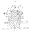
- a vehicle-use bearing apparatus 1 is a structure applied to a follower-wheel side of a vehicle and includes a hub wheel 2 as a follower shaft to which a wheel is mounted and a double row rolling bearing 3 for supporting the hub wheel 2 for rotation with respect to a vehicle body about an axial center P.
- This bearing 3 is a double row angular contact ball bearing with vertex of contact angles outside of bearing.
- the hub wheel 2 is formed of a small-diameter portion 5 corresponding to a vehicle inner side, a large-diameter portion 6 corresponding to a vehicle outer side, and a hub flange 7 formed at the large-diameter portion 6 to project radially outward.
- a brake disc rotor (not shown) is fixed to the hub flange 7.
- a caulking cylindrical recessed portion 8 On an end face of the small diameter portion 5 of the hub wheel 2 on the vehicle inner side, a caulking cylindrical recessed portion 8, which is shown with a phantom line, is formed by turning. By deforming a peripheral portion of the cylindrical recessed portion 8 to increase a diameter of the peripheral portion radially outward, a caulked portion 9 is formed. This caulked portion 9 is pressed against an end face of an inner ring member 13 which will be described later.
- the bearing 3 includes a single outer ring member 10, a plurality of balls 11 and 12, the inner ring member 13, and retainers 14.
- a mounting flange 15 is formed to project radially outward on an outer peripheral face of the outer ring member 10 and a support member (not shown) called a knuckle or a carrier is fixed to the flange 15.
- a support member (not shown) called a knuckle or a carrier is fixed to the flange 15.
- the outer ring member 10 has on an inner peripheral face thereof two rows of raceways adjacent to each other in an axial direction.
- the plurality of balls 11 and 12 are arranged as rolling elements in the two rows of raceways in the outer ring member 10.
- the inner ring member 13 has on an outer peripheral face thereof a single raceway which pairs up with the raceway in the outer ring member 10 on the vehicle inner side.
- the inner ring member 13 is fitted with an outer peripheral face of the hub wheel 2.
- a necessary area of the outer peripheral face of the hub wheel 2 is used as a raceway which pairs up with the raceway in the outer ring member 10 on the vehicle outer side.
- the cylindrical recessed portion 8 is formed at the end portion of the small-diameter portion 5 of the hub wheel 2 on the vehicle inner side.
- the outer ring member 10 is mounted to the hub wheel 2 through the balls 12 for the row on the vehicle outer side and the inner ring member 13 is mounted to the hub wheel 2 through the balls 11 for the row on the vehicle inner side.
- a caulking jig 17 is pushed against the cylindrical recessed portion 8 in such a manner as to be fitted in the cylindrical recessed portion 8 while fitting the large-diameter portion 6 of the hub wheel 2 over a caulking receiving jig 16.
- the caulking jig 17 is rolled about the axial center P of the hub wheel 2 and the peripheral portion of the cylindrical recessed portion 8 is deformed in such a direction as to increase the diameter of the peripheral portion to thereby form the caulked portion 9 and the caulked portion 9 is crimped onto the end face of the inner ring member 13.
- the inner ring member 13 can be prevented from coming off the hub wheel 2 and predetermined pre-loads are applied to the respective rolling elements 11 and 12 to thereby manufacture the vehicle-use bearing apparatus 1.
- the present embodiment is characterized in that steel material including 0.37 % by weight to 1.10 % by weight carbon is used as steel material of which the hub wheel 2 is formed.
- steel material including 0.37 % by weight to 1.10 % by weight carbon is used as steel material of which the hub wheel 2 is formed.
- a percentage of sulfur content is adjusted to be 0.020 % by weight or less and more desirably 0.015 % by weight or less.
- JIS S40C to S58C As types of the steel material of which the hub wheel 2 is formed, there are JIS S40C to S58C, SAE 1040 to SAE 1095, SUJ 1 to SUJ 5, and SAE 52100, for example.
- Specified percentages of carbon content of the respective steel materials are 0.37 % by weight to 0.61 % by weight, 0.37 % by weight to 1.03 % by weight, 0.95 % by weight to 1.10 % by weight, and 0.98 % by weight to 1.10 % by weight in order.
- a horizontal axis designates a percentage (% by weight) of sulfur content in the steel material.
- a vertical axis designates a rate of occurrence (%) of a crack in the caulked portion 9 when the steel material of the vehicle-use bearing apparatus 1 is subjected to caulking as describe above.
- the caulking at this time is carried out on conditions that a pressurizing force applied by the caulking jig 17 to the hub wheel 2 is 98kN and that the number of revolutions of the caulking jig 17 is 1,000 rpm.
- the reason why occurrence of the crack can be prevented in forming the caulked portion 9 is considered that generation of manganese sulfide which is a nonmetallic inclusion can be suppressed by setting the percentage of sulfur content at the above value.
- the present invention can also be applied to a vehicle-use bearing apparatus 1 on a side of a follower wheel as shown in FIG. 3.
- This vehicle-use bearing apparatus 1 includes a hub wheel 2, a double row rolling bearing 3, and an outer ring member 10.
- the bearing 3 includes a single outer ring member 22, two inner ring members 20 and 21 adjacent to each other in an axial direction, and a plurality of balls 11 and 12.
- the bearing 3 also constitutes a double row angular contact ball bearing with vertex of contact angles outside of bearing as well as the case of FIG. 1.
- the outer ring member 22 has on an inner peripheral face thereof two rows of raceways adjacent to each other in the axial direction.
- the inner ring 20 on the vehicle inner side has a raceway which pairs up with the raceway in the outer ring member 22 on the vehicle inner side.
- the inner ring 21 on the vehicle outer side has a raceway which pairs up with the raceway in the outer ring member 22 on the vehicle outer side.
- the plurality of balls 11 and 12 are arranged in two rows between both the raceways in the outer ring member 22 and the raceways in both the inner ring members 20 and 21.
- a mounting flange 15 such as a knuckle is not provided to an outer peripheral face of the outer ring member 22 of the bearing 3.
- the outer ring member 10 including the mounting flange 15 is fixed to the outer peripheral face of the outer ring 22 of the bearing 3 through locating snap rings 10a and 10b.
- the hub wheel 2 includes a caulked portion 9 formed by expanding a cylindrical recessed portion 8 at an end portion of the hub wheel 2 on the vehicle inner side radially outward with a caulking jig 17 and caulking the cylindrical recessed portion 8 onto an end face of the inner ring member 20 on the vehicle inner side.
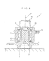
- the present invention can be applied to a vehicle-use bearing apparatus 1 on a side of a flower wheel as shown in FIG. 4.
- This vehicle-use bearing apparatus 1 has a structure formed by integrating the outer ring member 22 and the other outer ring member 10 in the bearing 3 of the vehicle-use bearing apparatus 1 shown in FIG. 3. Because other structures are similar to those of the vehicle-use bearing apparatus 1 shown in FIG. 3, description of them will be omitted.
- the invention can be applied to a vehicle-use bearing apparatus 1 on a side of a driving wheel as shown in FIG. 5.
- a central hole 23 through which a power transmitting shaft (not shown) is inserted is formed at a center of the hub wheel 2.
- the present invention can be applied to a vehicle-use bearing apparatus 1 on a side of a driving wheel as shown in FIG. 6.
- a central hole 23 through which a power transmitting shaft (not shown) is inserted for rotation integral with the hub wheel 5 is formed at a center of the hub wheel 2 of the vehicle-use bearing apparatus 1 shown in FIG. 1. Because other structures are similar to those of the vehicle-use bearing apparatus 1 shown in FIG. 1, description of them will be omitted.
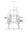
- the present invention can be applied to a vehicle-use bearing apparatus 1 on a side of a driving wheel as shown in FIG. 7.
- a hollow rotary shaft 26 is formed integrally with a bowl-shaped outer ring member 25 of a constant velocity joint to which a driving force of an engine is transmitted.
- the hollow rotary shaft 26 is inserted into a central hole 23 of the hub wheel 2 from a vehicle inner side.
- the bowl-shaped outer ring member 25 and the hub wheel 2 are supported on an outer ring member 10 through balls 11 and 12 for rotation about an axial center P.
- the hub wheel 2, the bowl-shaped outer ring member 25, the outer ring member 10 and the balls 11 and 12 also constitute the double row angular contact ball bearing with vertex of contact angles outside of bearing.
- the hub wheel 2 has on an outer peripheral face thereof a hub flange 7 and the outer ring member 10 has on an outer peripheral face thereof a mounting flange 15.
- a caulking jig 17 is fitted in a caulking cylindrical recessed portion 8 at an end portion of the rotary shaft 26 on a vehicle outer side.
- the cylindrical recessed portion 8 is crimped onto an end face of the hub wheel 2 by rolling the caulking jig 17 about the axial center P.
- the present invention can be applied to a vehicle-use bearing apparatus 1 on a side of a follower wheel as shown in FIG. 8.
- a hub wheel 2 and an inner ring member 13 are supported for rotation about an axial center P and constitute the double row angular contact ball bearing with vertex of contact angles outside of bearing on an outer ring member 10 through double-row conical rollers 28 and 29 as rolling elements.
- the inner ring member 13 is fitted over an end portion of the hub wheel.
- a midpoint area of an outer peripheral face of the hub wheel 2 is used as an inner ring raceway for the conical rollers 29 in the row on a vehicle outer side.
- An outer peripheral face of the inner ring member 13 is used as an inner ring raceway for the conical rollers 28 in the row on a vehicle inner side.
- the hub wheel 2 has on an outer peripheral face thereof a hub flange 7 and the outer ring member 10 has on an outer peripheral face thereof a mounting flange 15.
- a caulking jig 17 is fitted in a caulking cylindrical recessed portion 8 at the end portion of the hub wheel 2 on a vehicle inner side.
- the caulking cylindrical recessed portion 8 is crimped onto an end face of the inner ring member 13 by rolling the caulking jig 17 about the axial center P.
- vehicle-use bearing apparatus 1 for which the double-row conical rollers 28 and 29 are used as shown in FIG. 8, there is a vehicle-use bearing apparatus (not shown) in which a pair of inner ring members adjacent to each other in an axial direction are provided and outer peripheral faces of the inner ring members are respectively used as inner ring raceway faces for the conical rollers.
- a central hole through which a power-transmitting shaft is inserted is formed at a center of a hub wheel to use the hub wheel as a vehicle-use bearing apparatus on a side of a driving wheel.
- a double row rolling bearing 3 for supporting a hub wheel 2 for rotation about an axial center P includes a pair of inner ring members 20 and 21 through which the hub wheel 2 is inserted for rotation with the inner ring members 20 and 21 about the axial center P and an outer ring member 10 disposed on an outside through balls 11 and 12 for which outer peripheral faces of the respective inner ring members 20 and 21 are used as inner ring raceway faces.
- This double row rolling bearing 3 constitutes a double row angular contact ball bearing with vertex of contact angles outside of bearing.
- the outer ring member 10 of this double row rolling bearing 3 is press fitted into a through hole of a support member (knuckle or carrier) 30 mounted to a vehicle body.
- the hub wheel 2 has a hub flange 7 on and to which a brake disc rotor 31 is placed and mounted and a rotary shaft 26 integrally formed with a bowl-shaped outer ring member 25 of a constant velocity joint is fitted in a central hole of the hub wheel 2 for rotating with the hub wheel 2.
- a caulked portion 9 is formed by respectively deforming opposite portions of the through hole of the support member 30 radially inward toward end faces of the outer ring 10.
- a percentage of carbon content is adjusted to be 0.37 % by weight to 1.10 % by weight and a percentage of sulfur content is adjusted to be 0.020 % by weight or less and desirably 0.015 % by weight or less in the steel material of which the caulked portion 9 is formed.
- the receiving position is not limited to this and may be a flange portion, for example. It is also possible to carry out caulking while employing two or more portions among the boss portion, the end portion, and the flange portion as the receiving positions.
- a crack occurs in the caulked portion 9 in about 3 % of products if the percentage of sulfur content is 0.025 % by weight. Therefore, when the alloy steel of a kind of SUJ2 is used, the percentage of carbon content is set at 1.10 % by weight and the percentage of sulfur content is adjusted to be 0.020 % by weight to produce the products. As a result, generation of MnS (manganese sulfide) which is a nonmetallic inclusion can be suppressed and a crack hardly occurs in the caulked portion 9 similarly to the case in which S55C is used. When the percentage of sulfur content is set at 0.015 % by weight or less, a rate of occurrence of the crack becomes zero, no products are discarded, a cost of the product is stabilized, and supply performance of the product can be improved.
- MnS manganesese sulfide
- S55C or SUJ2 is employed as the steel type to be used in each the above embodiment
- the steel type is not limited to this and it is also possible to use S40C to S58C, SAE1040 to SAE1095, SUJ1 to SUJ5, and SAE52100 excluding S55C and SUJ2 in some cases and to set the percentage of sulfur content at 0.020 % by weight or 0.015 % by weight in the steel material. In any case, operations and effects similar to those of each the above embodiment can be obtained.
Landscapes
- Engineering & Computer Science (AREA)
- Mechanical Engineering (AREA)
- General Engineering & Computer Science (AREA)
- Chemical & Material Sciences (AREA)
- Materials Engineering (AREA)
- Metallurgy (AREA)
- Organic Chemistry (AREA)
- Rolling Contact Bearings (AREA)
- Mounting Of Bearings Or Others (AREA)
Abstract
Description
Claims (14)
- A vehicle-use bearing apparatus comprising:wherein an end portion of said hub wheel is expanded radially outward toward an inner ring member provided to said rolling bearing to be formed into a caulked portion anda hub wheel formed of steel material to which a wheel is mounted; anda rolling bearing mounted to an outer periphery of said hub wheel,
a percentage of sulfur content is adjusted to be 0.020 % by weight or less in steel material of which said caulked portion is formed. - The vehicle-use bearing apparatus according to claim 1, wherein a steel type of the steel material of which said caulked portion is formed is one selected from among JIS S40C to S58C including 0.37 % by weight to 0.61 % by weight carbon, SAE 1040 to 1095 including 0.37 % by weight to 1.03 % by weight carbon, SUJ1 to SUJ5 including 0.95 % by weight to 1.10 % by weight carbon, and SAE 52100 including 0.98 % by weight to 1.10 % by weight carbon.
- The vehicle-use bearing apparatus according to claim 1, wherein said rolling bearing includes a single outer ring member having two rows of raceways adjacent to each other in an axial direction, a plurality of rolling elements arranged in said two rows of raceways, and an inner ring member having a single raceway which pairs up with said raceway in said outer ring member on a vehicle inner side and is fitted with an outer peripheral face of said hub wheel and a necessary area of said outer peripheral face of said hub wheel is used as a raceway which pairs up with said raceway in said outer ring member on a vehicle outer side.
- The vehicle-use bearing apparatus according to claim 3, wherein said hub wheel has a central hole through which a rotary shaft is inserted for rotation with said hub wheel.
- The vehicle-use bearing apparatus according to claim 1, wherein said rolling bearing includes a single first outer ring member having two rows of raceways adjacent to each other in an axial direction, an inner ring member on a vehicle outer side and having a single raceway which pairs up with said raceway in said first outer ring member on said vehicle outer side, an inner ring member on a vehicle inner side and having a single raceway which pairs up with said raceway in said first outer ring member on said vehicle inner side, and a plurality of rolling elements arranged in two rows between both said raceways in said first outer ring member and said respective raceways in both said inner ring members and
said vehicle-use bearing apparatus includes a second outer ring member connected to an outer peripheral face of said first outer ring member for rotation with said first outer ring member and having a mounting flange for fixing said first outer ring member to a vehicle body. - The vehicle-use bearing apparatus according to claim 1, wherein said rolling bearing includes a single outer ring member having two rows of raceways adjacent to each other in an axial direction, an inner ring member on a vehicle outer side and having a single raceway which pairs up with said raceway in said outer ring member on said vehicle outer side, an inner ring member on a vehicle inner side and having a single raceway which pairs up with said raceway in said outer ring member on said vehicle inner side, and a plurality of rolling elements arranged in two rows between both said raceways in said outer ring member and said respective raceways in both said inner ring members and a mounting flange for fixing said outer ring member to a vehicle body is provided to an outer peripheral face of said outer ring member.
- The vehicle-use bearing apparatus according to claim 6, wherein said hub wheel has a central hole through which a rotary shaft is inserted for rotation with said hub wheel.
- A vehicle-use bearing apparatus comprising a hub wheel formed of steel material to which a wheel is mounted and
a rolling bearing mounted to an outer periphery of said hub wheel,
wherein an end portion of said hub wheel is expanded radially outward toward an inner ring provided to said rolling bearing to be formed into a caulked portion and
a percentage of sulfur content is adjusted to be 0.015 % by weight or less in steel material of which said caulked portion is formed. - The vehicle-use bearing apparatus according to claim 8, wherein a steel type of the steel material of which said caulked portion is formed is one selected from among JIS S40C to S58C including 0.37 % by weight to 0.61 % by weight carbon, SAE 1040 to 1095 including 0.37 % by weight to 1.03 % by weight carbon, SUJ1 to SUJ5 including 0.95 % by weight to 1.10 % by weight carbon, and SAE 52100 including 0.98 % by weight to 1.10 % by weight carbon.
- A vehicle-use bearing apparatus comprising:wherein an end portion of said rotary shaft is expanded radially outward toward a hub wheel to be formed into a caulked portion anda hub wheel to which a wheel is mounted and which has a central hole; anda rotary shaft formed of steel material and inserted through said central hole of said hub wheel,
a percentage of sulfur content is adjusted to be 0.020 % by weight or less in steel material of which said caulked portion is formed. - The vehicle-use bearing according to claim 10, wherein said rotary shaft is formed of a rotary shaft integrally formed with an outer ring member of a constant velocity joint to which a driving force of an engine is transmitted.
- The vehicle-use bearing apparatus according to claim 10, wherein a steel type of the steel material of which said caulked portion is formed is one selected from among JIS S40C to S58C including 0.37 % by weight to 0.61 % by weight carbon, SAE 1040 to 1095 including 0.37 % by weight to 1.03 % by weight carbon, SUJ1 to SUJ5 including 0.95 % by weight to 1.10 % by weight carbon, and SAE 52100 including 0.98 % by weight to 1.10 % by weight carbon.
- A vehicle-use bearing apparatus comprising:wherein said support member includes a fitted portion to be fitted over said outer ring member of said rolling bearing and a mounting flange formed on an outer peripheral face of said fitted portion to be mounted to said vehicle body,a rolling bearing; anda support member for fixing an outer ring member provided to said rolling bearing to a vehicle body,
an end portion of said fitted portion of said support member is deformed radially outward toward an end portion of said outer ring member of said rolling bearing to be formed into a caulked portion, and
a percentage of sulfur content is adjusted to be 0.020 % by weight or less in steel material of which said caulked portion is formed. - The vehicle-use bearing apparatus according to claim 13, wherein a steel type of the steel material of which said caulked portion is formed is one selected from among JIS S40C to S58C including 0.37 % by weight to 0.61 % by weight carbon, SAE 1040 to 1095 including 0.37 % by weight to 1.03 % by weight carbon, SUJ1 to SUJ5 including 0.95 % by weight to 1.10 % by weight carbon, and SAE 52100 including 0.98 % by weight to 1.10 % by weight carbon.
Applications Claiming Priority (6)
| Application Number | Priority Date | Filing Date | Title |
|---|---|---|---|
| JP2000370691 | 2000-12-05 | ||
| JP2000370691 | 2000-12-05 | ||
| JP2001260878 | 2001-08-30 | ||
| JP2001260878 | 2001-08-30 | ||
| JP2001334695 | 2001-10-31 | ||
| JP2001334695A JP2003148499A (en) | 2000-12-05 | 2001-10-31 | Bearing device for vehicle |
Publications (2)
| Publication Number | Publication Date |
|---|---|
| EP1213156A2 true EP1213156A2 (en) | 2002-06-12 |
| EP1213156A3 EP1213156A3 (en) | 2009-02-25 |
Family
ID=27345374
Family Applications (1)
| Application Number | Title | Priority Date | Filing Date |
|---|---|---|---|
| EP01127817A Withdrawn EP1213156A3 (en) | 2000-12-05 | 2001-11-22 | Vehicle-use bearing apparatus |
Country Status (3)
| Country | Link |
|---|---|
| US (2) | US6722786B2 (en) |
| EP (1) | EP1213156A3 (en) |
| JP (1) | JP2003148499A (en) |
Cited By (2)
| Publication number | Priority date | Publication date | Assignee | Title |
|---|---|---|---|---|
| ITTO20090934A1 (en) * | 2009-11-28 | 2011-05-29 | Skf Ab | HUB-HUB HOLDER UNIT FOR HIGH-PERFORMANCE MOTOR VEHICLES |
| CN104903603A (en) * | 2013-01-09 | 2015-09-09 | Ntn株式会社 | Bearing device for wheel |
Families Citing this family (16)
| Publication number | Priority date | Publication date | Assignee | Title |
|---|---|---|---|---|
| JP2003148499A (en) * | 2000-12-05 | 2003-05-21 | Koyo Seiko Co Ltd | Bearing device for vehicle |
| EP2253483B1 (en) * | 2001-03-29 | 2012-07-04 | NTN Corporation | Bearing device for drive wheel |
| JP4526998B2 (en) * | 2005-04-22 | 2010-08-18 | Ntn株式会社 | Drive wheel bearing device |
| US20070104405A1 (en) * | 2005-11-10 | 2007-05-10 | Chia-Wei Lin | Bearing device for bicycles |
| US7658173B2 (en) * | 2006-10-31 | 2010-02-09 | Lycoming Engines, A Division Of Avco Corporation | Tappet for an internal combustion engine |
| JP2008247075A (en) * | 2007-03-29 | 2008-10-16 | Jtekt Corp | Driving force transmission device for four-wheel drive vehicles |
| JP2008247316A (en) * | 2007-03-30 | 2008-10-16 | Jtekt Corp | Rolling bearing device for wheel and manufacturing method thereof |
| JP2008296694A (en) * | 2007-05-30 | 2008-12-11 | Ntn Corp | Flange structure |
| EP2105322B1 (en) | 2008-03-28 | 2012-01-18 | JTEKT Corporation | Wheel bearing assembly, manufacturing method therefor, and calk jig |
| US8845203B2 (en) * | 2008-11-06 | 2014-09-30 | Kyklos Bearing International, Inc. | Wheel bearing assembly |
| US20100210369A1 (en) * | 2009-02-17 | 2010-08-19 | Jtekt Corporation | Wheel bearing device and manufacturing method therefor |
| CN101852250B (en) * | 2010-04-29 | 2011-11-30 | 中国科学院上海技术物理研究所 | Device and method for regulating pair of back to back inner and outer spacers of angular contact bearing |
| DE102012207054A1 (en) * | 2012-04-27 | 2013-10-31 | Schaeffler Technologies AG & Co. KG | Inner ring with axial extension |
| JP2013227676A (en) * | 2013-04-12 | 2013-11-07 | Nsk Ltd | Bearing device for supporting wheel |
| CN104357730A (en) * | 2014-11-17 | 2015-02-18 | 柳州市俊杰汽配制造有限公司 | Automobile wheel hub |
| JP6930560B2 (en) * | 2019-08-20 | 2021-09-01 | 日本精工株式会社 | Hub unit bearing manufacturing method, rocking caulking device, and vehicle manufacturing method |
Family Cites Families (6)
| Publication number | Priority date | Publication date | Assignee | Title |
|---|---|---|---|---|
| EP1319854B1 (en) | 1997-01-17 | 2005-08-03 | Nsk Ltd | Bearing unit for vehicle wheel support |
| JPH10196661A (en) | 1997-01-17 | 1998-07-31 | Nippon Seiko Kk | Hub unit for wheel support |
| JP3845942B2 (en) * | 1997-03-31 | 2006-11-15 | 日本精工株式会社 | Wheel support hub unit |
| GB9713343D0 (en) * | 1997-06-24 | 1997-08-27 | Timken Co | Process and machine for uniting rotatable machine components |
| US6640438B2 (en) * | 1998-06-22 | 2003-11-04 | The Timken Company | Process and machine for uniting rotatable machine components |
| JP2003148499A (en) * | 2000-12-05 | 2003-05-21 | Koyo Seiko Co Ltd | Bearing device for vehicle |
-
2001
- 2001-10-31 JP JP2001334695A patent/JP2003148499A/en active Pending
- 2001-11-22 EP EP01127817A patent/EP1213156A3/en not_active Withdrawn
- 2001-12-05 US US10/007,813 patent/US6722786B2/en not_active Expired - Lifetime
-
2004
- 2004-02-20 US US10/783,447 patent/US7290939B2/en not_active Expired - Lifetime
Non-Patent Citations (1)
| Title |
|---|
| None |
Cited By (4)
| Publication number | Priority date | Publication date | Assignee | Title |
|---|---|---|---|---|
| ITTO20090934A1 (en) * | 2009-11-28 | 2011-05-29 | Skf Ab | HUB-HUB HOLDER UNIT FOR HIGH-PERFORMANCE MOTOR VEHICLES |
| EP2327568A1 (en) * | 2009-11-28 | 2011-06-01 | Aktiebolaget SKF | A hub bearing-hub carrier unit for high-performance motor vehicles |
| CN104903603A (en) * | 2013-01-09 | 2015-09-09 | Ntn株式会社 | Bearing device for wheel |
| CN104903603B (en) * | 2013-01-09 | 2018-04-06 | Ntn株式会社 | Wheel bearing arrangement |
Also Published As
| Publication number | Publication date |
|---|---|
| EP1213156A3 (en) | 2009-02-25 |
| JP2003148499A (en) | 2003-05-21 |
| US20020067875A1 (en) | 2002-06-06 |
| US6722786B2 (en) | 2004-04-20 |
| US7290939B2 (en) | 2007-11-06 |
| US20040165804A1 (en) | 2004-08-26 |
Similar Documents
| Publication | Publication Date | Title |
|---|---|---|
| US6722786B2 (en) | Vehicle-use bearing apparatus | |
| US9903417B2 (en) | Assembly procedure of a bearing unit—HUB flange | |
| US20060223643A1 (en) | Exterior joint part comprising a supporting disc | |
| JPH1095203A (en) | Rolling bearing unit for wheel support | |
| JP5278935B2 (en) | Wheel bearing device | |
| US10655672B2 (en) | Method and device for producing an angular contact roller bearing | |
| US6921137B2 (en) | Wheel-use bearing apparatus | |
| US11028875B1 (en) | Assembly with a housing and an outer bearing race that are formed of dissimilar metals, the assembly being configured to retain the outer bearing race to the housing over a range of temperatures | |
| US7175349B2 (en) | Wheel rotation supporting apparatus | |
| JP2003211908A (en) | Rolling bearing device | |
| JP2003090350A (en) | Fixing structure of bearing for wheel and bearing for wheel | |
| JP2007126087A (en) | Bearing device for wheel | |
| JP4706242B2 (en) | Method of manufacturing rolling bearing device and rolling bearing device | |
| JP7440349B2 (en) | Rolling bearing unit for wheel support | |
| JP3757309B2 (en) | Pinion shaft support bearing unit | |
| JP4883693B2 (en) | Assembly method for wheel bearing device | |
| US20070025654A1 (en) | Tapered roller bearing assembly and method of fabricating the same | |
| JP2007321988A (en) | Vehicle bearing device | |
| JP2011140302A (en) | Bearing device for vehicle | |
| JP2004116716A (en) | Rolling bearing device | |
| JP2015117720A (en) | Constant velocity joint boots | |
| EP1489320A1 (en) | Rolling bearing unit for supporting wheel | |
| JP2003294031A (en) | Rolling bearing unit | |
| JP2022134633A (en) | Wheel bearing device | |
| WO2007069653A1 (en) | Bearing device for wheel and axle module with the same |
Legal Events
| Date | Code | Title | Description |
|---|---|---|---|
| PUAI | Public reference made under article 153(3) epc to a published international application that has entered the european phase |
Free format text: ORIGINAL CODE: 0009012 |
|
| AK | Designated contracting states |
Kind code of ref document: A2 Designated state(s): AT BE CH CY DE DK ES FI FR GB GR IE IT LI LU MC NL PT SE TR |
|
| AX | Request for extension of the european patent |
Free format text: AL;LT;LV;MK;RO;SI |
|
| RAP1 | Party data changed (applicant data changed or rights of an application transferred) |
Owner name: JTEKT CORPORATION |
|
| PUAL | Search report despatched |
Free format text: ORIGINAL CODE: 0009013 |
|
| AK | Designated contracting states |
Kind code of ref document: A3 Designated state(s): AT BE CH CY DE DK ES FI FR GB GR IE IT LI LU MC NL PT SE TR |
|
| AX | Request for extension of the european patent |
Extension state: AL LT LV MK RO SI |
|
| 17P | Request for examination filed |
Effective date: 20090813 |
|
| AKX | Designation fees paid |
Designated state(s): DE FR GB IT |
|
| 17Q | First examination report despatched |
Effective date: 20091109 |
|
| STAA | Information on the status of an ep patent application or granted ep patent |
Free format text: STATUS: THE APPLICATION IS DEEMED TO BE WITHDRAWN |
|
| 18D | Application deemed to be withdrawn |
Effective date: 20100520 |