EP1212909B1 - Cell breathing reduction in a cellular network - Google Patents
Cell breathing reduction in a cellular network Download PDFInfo
- Publication number
- EP1212909B1 EP1212909B1 EP00959079A EP00959079A EP1212909B1 EP 1212909 B1 EP1212909 B1 EP 1212909B1 EP 00959079 A EP00959079 A EP 00959079A EP 00959079 A EP00959079 A EP 00959079A EP 1212909 B1 EP1212909 B1 EP 1212909B1
- Authority
- EP
- European Patent Office
- Prior art keywords
- maximum coverage
- frequency
- coverage frequency
- frequencies
- plural
- Prior art date
- Legal status (The legal status is an assumption and is not a legal conclusion. Google has not performed a legal analysis and makes no representation as to the accuracy of the status listed.)
- Expired - Lifetime
Links
Images


Classifications
-
- H—ELECTRICITY
- H04—ELECTRIC COMMUNICATION TECHNIQUE
- H04W—WIRELESS COMMUNICATION NETWORKS
- H04W16/00—Network planning, e.g. coverage or traffic planning tools; Network deployment, e.g. resource partitioning or cells structures
- H04W16/02—Resource partitioning among network components, e.g. reuse partitioning
- H04W16/12—Fixed resource partitioning
-
- H—ELECTRICITY
- H04—ELECTRIC COMMUNICATION TECHNIQUE
- H04W—WIRELESS COMMUNICATION NETWORKS
- H04W16/00—Network planning, e.g. coverage or traffic planning tools; Network deployment, e.g. resource partitioning or cells structures
- H04W16/02—Resource partitioning among network components, e.g. reuse partitioning
Definitions
- the present invention pertains to cellular telecommunications, and particularly to maintaining sufficient cell size in a cellular telecommunications system.
- Cellular telecommunications systems employ a wireless link (e.g., air interface) between the (mobile) user equipment and a base station (BS).
- the base station has transmitters and receivers for radio connections with numerous mobile user equipment units.
- the mobile user equipment units can take the form of cellular telephones or laptop computers with mobile termination, for example.
- the effective geographical transmission/reception range of a base station defines a cell served by that base station.
- the cell is the territory in which a user equipment unit can be located and still remain in radio communication over the air interface with the associated base station.
- the base stations are preferably situated so that the cells served thereby are slightly overlapping proximate their perimeters or at least contiguous, thereby permitting a user equipment unit to move from one cell to another cell and remain within the telecommunications network.
- a user equipment unit participating in a mobile connection e.g., telephone call
- a handoff or handover of the mobile connection occurs.
- the mobile connection is handled through the second base station rather than the first station as formerly.
- Radio coverage is a very important characteristic for all cellular telecommunication systems.
- Cell size is a major factor in obtaining good geographical coverage. The cell size is dependent upon the maximum allowed path loss between the user equipment unit and the base station. The greater the maximum allowed path loss, the further a user equipment unit can move away from the base station and still receive a sufficient signal. This means that if the maximum allowed path loss is increased, then the cell size is increased. Conversely, if the maximum allowed path loss is decreased, then the cell size is reduced.
- CDMA code division multiple access
- the information transmitted between a base station and a particular mobile station is modulated by a mathematical code (such as spreading code) to distinguish it from information for other mobile stations which are utilizing the same radio frequency.
- a mathematical code such as spreading code
- the individual radio links are discriminated on the basis of codes.
- Various aspects of CDMA are set forth in Garg, Vijay K. et al., Applications of CDMA in Wireless/Personal Communications, Prentice Hall (1997 ).
- the same base band signal with suitable spreading is sent from several base stations with overlapping coverage. The mobile terminal can thus receive and use signals from several base stations simultaneously.
- a CDMA base station attempts to maintain a sufficient Signal to Interference Ratio (SIR) in communications with each mobile station that it currently serves.
- SIR Signal to Interference Ratio
- a base station measures the received signal from each of the mobile stations in order to determine the Signal to Interference Ratio (SIR).
- SIR Signal to Interference Ratio
- the SIR is compared with a target value SIR. If the SIR measured for a particular mobile station is less than the target value SIR, the base station commands the mobile station to increase its power in order that a stronger signal can be received at the base station. On the other hand, if the SIR determined for the particular station is greater than the target value SIR, the base station requests the mobile station to decrease its power.
- a power control loop is established between the base station and the mobile station, with an uplink aspect of the power control loop involving the mobile station transmitting to the base station and with the base station, upon receiving the signal from the mobile station and comprising the SINR for the station with the target SIR, providing power control commands to the mobile station as a downlink aspect of the power control loop.
- An example CDMA power loop control system is disclosed in United States Patent No. 6,154,450 entitled “Signaling Method for CDMA Quality Based Power Control".
- the overall effect of cell breathing is that the cell size is reduced when the traffic is increased.
- Providing more cells e.g., a more dense population of base stations) is one way of compensating for this undesirable reduction of cell size.
- the provision of more cells may still result in varying cell coverage, e.g., cell breathing with respect even to the new cells.
- WO 98/52364 discloses a system and method for operating a cellular communication system wherein frequency reuse of available carrier frequencies is maximized, thereby maximizing system traffic capacity.
- the system includes an outer cell grid generated by a plurality of base station receivers connected to a common network controller. Within the grid of outer cells is at least one overlapping sub-grid of inner cells that may be generated by the same base stations as the outer cells, or which may be generated using separate base station transceivers located within the outer cell. At least two frequency reuse patterns are applied to the cells, one pattern for the outer cells and another, tighter pattern for the inner cells.
- What is needed, therefore, and an object of the present invention is a technique to reduce the effect of cell breathing in a telecommunications system.
- Traffic is allocated between plural radio frequencies utilized at a base station of a cellular telecommunications system according to a cell size strategy for a cell served by the base station.
- the traffic can be allocated between the plural frequencies utilized at the base station to maintain a cell size as having a predetermined coverage (e.g., to maximize cell size or maintain the cell size has having a predetermined geographical minimum), thereby reducing effects of cell breathing.
- the base station is operated so that at least one of its plural frequencies can be utilized as far away as a geographically constant cell perimeter.
- one of the plural frequencies utilized at the base station is selected as a maximum coverage frequency.
- the interference on the maximum coverage frequency is limited so that at least the maximum coverage frequency can be utilized throughout the cell, even to the constant cell perimeter.
- the total interference on the maximum coverage frequency is limited so that the maximum coverage frequency can be utilized at the furthermost extent of the cell.
- total interference on the maximum coverage frequency is measured and, if the total interference exceeds a predetermined threshold, (1) one or more connections carried by the maximum coverage frequency is released (handed over) to another one of the plural frequencies, and/or (2) newly requesting connections are required to be carried on the other frequency(ies).
- the total interference measurement for the maximum coverage frequency is made at the base station.
- the base station transfers its total interference measurement for the maximum coverage frequency to its radio network controller (RNC).
- the radio network controller (RNC) compares the total interference for the maximum coverage frequency to a constant coverage threshold value for the base station.
- the radio network controller realizes that the maximum coverage frequency requires protection.
- a resource allocation unit in the radio network controller can either (1) transfer existing connections from the maximum coverage frequency to the other frequency(ies), or (2) require that new connections utilize the frequency(ies) other than the maximum coverage frequency.
- the radio network controller can suspend protection efforts for the maximum coverage frequency.
- connection controlled mode In another mode, known as the connection controlled mode, the available frequencies are ordered in a list.
- the plural frequencies on the ordered list are ranked in a preferred order of usage with the maximum coverage frequency being the one that is used last (i.e., a least preferred frequency).
- the connection controlled mode when there is a new connection, the system tires to allocate according to the ordered list with the maximum coverage frequency being utilized only as a last resort.
- the connection controlled mode there is also the possibility also to limit the number of connections.
- the traffic controlled mode In yet another mode, known as the traffic controlled mode, the amount of traffic occurring on each frequency is monitored and used as an estimate of the load or interference on each frequency. High traffic connections can be allocated to frequencies other than the maximum coverage frequency.
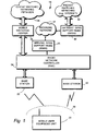
- Fig. 1 shows a telecommunications network 18 in which a user equipment unit 20 communicates with one or more base stations 22 over air interface (e.g., radio interface) 23.
- Base stations 22 are connected by terrestrial lines (or microwave) to radio network controller (RNC) 24 [also known as a base station controller (BSC) in some networks].
- RNC radio network controller
- the radio network controller (RNC) 24 is, in turn, connected through a control node known as the mobile switching center 26 to circuit-switched telephone networks (PSTN/ISDN) represented by cloud 28.
- PSTN/ISDN circuit-switched telephone networks
- radio network controller (RNC) 24 is connected to Serving GPRS Support Node (SGSN) 25 and through backbone network 27 to a Gateway GRPS support node (GGSN) 30, through which connection is made with packet-switched networks (e.g., the Internet, X.25 external networks) represented by cloud 32.
- SGSN Serving GPRS Support Node
- GGSN Gateway GRPS support node
- radio network controller (RNC) 24 orchestrates participation of the plural base stations 22 which may be involved in the connection or session, since user equipment unit 20 may be geographically moving and handover may be occurring relative to the base stations 22.
- radio network controller (RNC) 24 picks frames of user information from one or more base stations 22 to yield a connection between user equipment unit 20 and the other party, whether that party be in PSTN/IDSN 28 or on the packet-switched networks (e.g., the Internet) 32.
- RNC radio network controller
- channel refers to CDMA channel, which for any mobile station is defined in terms of an RF frequency and a particular code sequence.
- Fig. 2A shows a cell C served by a representative one of the base stations (which is identified simply as base station 22).
- the base station 22 and cell C are designed so that, under reasonable traffic conditions, a frequency utilized by base station 22 (either downlink or uplink frequency) is effective for connections with user equipment units located at a nominal radius R NOMINAL from base station 22.
- cell C has a nominal perimeter P NOMINAL .
- the "MS"s in Fig. 2A represent locations of active user equipment units (e.g., mobile stations) in cell C.
- Fig. 2B illustrates a heavy traffic situation for cell C as conventionally operated.
- there may be only one frequency utilized for each directional link with respect to base station 22 e.g., only one frequency for the uplink and only one frequency for the downlink), or (if multiple frequencies are provided) no coordination between the multiple frequencies for sake of cell coverage.
- Fig. 2B shows cell C having many more user equipment units MSs being shown than in Fig. 2A .
- the frequency utilized by base station 22 is effective only to a distance R EFFECTIVE shown in Fig. 2B (R EFFECTIVE ⁇ R NOMINAL ).
- the conventional operation and cell breathing of cell C has reduced the coverage area of cell C, e.g., reduced the coverage area of base station 22.
- user equipment units MS positioned at a radius from base station 22 greater than R EFFECTIVE shown in Fig. 2B cannot be served by base station 22 under these heavy traffic conditions.
- the present invention reduces effects of cell breathing in a manner illustrated, for example, in Fig. 2C .
- plural radio frequencies are utilized by base station 22 for each directional link (e.g., plural frequencies for the uplink and plural frequencies for the downlink).
- one of the plural frequencies is designated as a maximum coverage frequency.
- interference on the maximum coverage frequency is limited by allocation of traffic, when necessary, to another of the radio frequencies.
- the limiting of traffic e.g., by reallocation to other frequency(ies) keeps the maximum coverage frequency useable at the cell perimeter (assuming sufficient available channels).
- the cell C as operated by the present invention has a maximum geographical cell perimeter P MAX (P MAX being greater than P EFFECTIVE ).
- P MAX being greater than P EFFECTIVE
- traffic may be allocated so that the maximum coverage frequency is allocated to user equipment units in the outer ring region as shown in Fig. 2C .
- Other frequency(ies) are allocated to the remaining user equipment units (as shown by the inner ring region, which now has a radius smaller than R EFFECTIVE of Fig. 2B ).
- Fig. 3 shows in more detail components, pertinent to the present invention, of an example base station 22 node and an example radio network controller (RNC) 24 node.
- Base station 22 is connected by a physical link 40 to radio network controller (RNC) 24.
- Physical link 40 is typically a terrestrial or microwave line.
- link 40 carries data and signaling packets between base station 22 and radio network controller (RNC) 24. Packets directed from base station 22 to radio network controller (RNC) 24 are said to form an uplink 42 between base station 22 and radio network controller (RNC) 24; packets directed from radio network controller (RNC) 24 to base station 22 are said to form an downlink 44 between base station 22 and radio network controller (RNC) 24.
- RNC radio network controller
- base station 22 includes radio transceiver 50 1 and radio transceiver 50 2 ; node controller 52; and, network interface 54.
- Base station 22 serves cell C.
- a particular user equipment unit 20 in the cell is able to decode only the portion of the signal transmitted (from either transceiver 50 1 or transceiver 50 2 ) which has been encoded by the code known to that particular station.
- the information transmitted by each user equipment unit 20 to base station 22 is encoded with a unique code particular to that user equipment unit and recognizable by base station 22 as being attributed to that station.
- the portion of a signal over which the code associated with a particular user equipment unit enables that user equipment unit to transmit or receive information relative to base station 22 is known as a "channel" for that station.
- controller 52 conducts the coding and decoding of signals applied to and received from radio transceiver 50.
- the signals encoded by controller 52 are primarily those obtained over link 40 from radio network controller (RNC) 24.
- the signals decoded by controller 52 are primarily those destined for radio network controller (RNC) 24 over link 40.
- Network interface 54 is connected between controller 52 and link 40 in order to accommodate the transmission of signals between base station 22 and radio network controller (RNC) 24.
- Radio network controller (RNC) 24 has its own network interface 60 connected to link 40.
- Network interface 60 is connected within radio network controller (RNC) 24 to diversity handoff (DHO) unit 62, node controller 64, and resource allocation unit (RAU) 66.
- DHO diversity handoff
- RAU resource allocation unit
- RAU resource allocation unit
- radio network controller (RNC) 24 can also be performed by a type of node referred to as base station controller (BSC) or mobile switching center (MSC). Moreover, the radio network controller (RNC) 24 is typically connected to a plurality of base stations for performing operations such as those above-described. In addition, radio network controller (RNC) 24 is usually connected to one or more other radio network controllers comprising the mobile telecommunications network. At least one of the radio network controllers of the mobile telecommunications network is connected to or forms part of a gateway to the wired portion of the public switched telephone network (PSTN).
- PSTN public switched telephone network
- Diversity handoff (DHO) unit 62 performs numerous functions, including but not limited to assisting the transition which occurs when a mobile station travels or roams into a cell handled by another base station. In addition, diversity handoff (DHO) unit 62 computes a target signal to interference/noise ratio (TSNR) for each base station for which radio network controller (RNC) 24 is responsible.
- TSNR target signal to interference/noise ratio
- the resource allocation unit (RAU) 66 of the embodiment of Fig. 3 includes a resource allocation table 100.
- the resource allocation table 100 has a list or table of potential radio frequency resources, and reflects the status (already allocated or available) for each resource.
- the resources on the resource allocation table 100 are grouped by uplink and downlink.
- the resource allocation table 100 includes two frequencies for the uplink and a corresponding two frequencies for the downlink. In other words, for this particular case there is one regular frequency pair and one maximum coverage frequency (MCF) pair.
- MMF maximum coverage frequency
- the resource allocation table 100 has plural records, and in particular a record for each channel of the frequency.
- Each record includes a status indication from which resource allocation unit (RAU) 66 can determine if the channel has already been allocated to a connection or remains available for a new connection.
- RAU resource allocation unit
- the record includes a connection identifier.
- the resource allocation table 100 of Fig. 3 is shown as having only two uplink frequencies and two downlink frequencies. It should be apparent that a greater number of uplink frequencies and two downlink frequencies can be employed.
- Fig. 4 shows various basic steps or operations performed by base station 22 and radio network controller (RNC) 24 in connection with the Fig. 3 example embodiment of the invention.
- RNC radio network controller
- various signal measurements are performed by base station 22.
- the strength (i.e., received power) of the signal on the uplink from the user equipment unit to base station 20 is monitored by base station 20.
- the strength of the signal on the uplink from the user equipment unit to base station 20 is monitored essentially continuously by base station 20.
- radio transceiver 50 is interrogated by controller 52 with respect to each channel (e.g., each user equipment unit) to ascertain the received power of the signal.
- controller 52 For each uplink frequency, controller 52 thus knows the received power for all user equipment units served by the uplink frequency of base station 20. For each frequency, including the maximum coverage frequency (MCF), the total interference is also measured.
- MCF maximum coverage frequency
- the controller 52 determines, with respect to each uplink frequency, both a signal strength for each channel and a total interference for the uplink frequency.
- controller 52 determines a signal to interference/noise ratio (SIR).
- SIR signal to interference/noise ratio
- controller 52 of base station 22 waits for a measurement time reporting interval.
- the controller 52 of base station 22 prepares a coverage assurance message (CAM).
- CAM coverage assurance message
- An example format of a coverage assurance message (CAM) is illustrated in Fig. 5 .
- the coverage assurance message (CAM) begins with a header 5-1, which identifies, e.g., the type of message as being a coverage assurance message (CAM).
- the header is followed by a field 5-2 which declares the number of frequencies reported in the coverage assurance message (CAM).
- Field 5-3 declares the total interference for the uplink maximum coverage frequency.
- Field 5-4 states the number of channels active for the maximum coverage frequency.
- Fields 5-5-1 through 5-5-j give the signal strength for each of the active channels for the maximum coverage frequency.
- field 5-6 declares the total interference for the uplink regular frequency (REGF).
- Field 5-7 states the number of channels active for the uplink regular frequency (REGF).
- Fields 5-8-1 through 5-8-q give the signal strength for each of the active channels for the uplink regular frequency (REGF). The values for total interference for each frequency, as well as the signal strength values for fields 5-5-1 through 5-5-j and fields 5-8-1 through 5-8-q, are obtained from step 4-1.
- the format of the coverage assurance message (CAM) as illustrated in Fig. 5 would have a value of "2" in the number of frequencies field 5-2 in order to reflect utilization on the uplink of both the maximum coverage frequency and the other uplink frequency (herein known as the regular frequency). It will be readily understood that, when resource allocation table 100 has more than two uplink frequencies, the coverage assurance message (CAM) also includes information for a corresponding number of more than two uplink frequencies.
- step 4-4 the base station 22 is shown as transmitting the coverage assurance message (CAM) to radio network controller (RNC) 24 over link 40. Thereafter, the controller 52 of base station 22 returns to step 4-2 to determine if it is time to report new measurement results (which are being essentially continuously taken at step 4-1). Upon expiration of a further measurement time reporting interval, a further coverage assurance message (CAM) will be prepared and transmitted, all as understood with respect to the foregoing discussion of step 4-3 and step 4-4.
- CAM coverage assurance message
- a broken line delineates steps performed by base station 22 (on the left of the broken line) and steps performed by radio network controller (RNC) 24 (on the right of the broken line).
- RNC radio network controller
- the transmission of the coverage assurance message (CAM) is reflected by the arrow labeled "CAM".
- Step 4-5 of Fig. 4 shows radio network controller (RNC) 24 awaiting, and then processing (e.g., decoding), the coverage assurance message (CAM) received from base station 22.
- RAU resource allocation unit
- the resource allocation unit (RAU) 66 determines whether the total interference value for the maximum coverage frequency exceeds a predetermined interference first threshold. As understood from Fig. 5 , the total interference value for the maximum coverage frequency is obtained from field 5-3 of the coverage assurance message (CAM). If the interference first threshold is exceeded, step 4-7 through step 4-9 are performed.
- the resource allocation unit (RAU) 66 chooses an existing connection to be reallocated from the maximum coverage frequency to the other frequency (the regular frequency).
- the resource allocation unit (RAU) 66 can note, from the records in resource allocation table 100, the connection identifier of an allocated channel for the uplink maximum coverage frequency, and change the connection from the maximum coverage frequency to a channel of the regular frequency.
- Such reallocation is accomplished by resource allocation unit (RAU) 66 at step 4-8.
- the resource allocation unit (RAU) 66 sets a MCF protection flag. As long as the MCF protection flag is set, all requests for new connections must be allocated a channel of the regular frequency. In other words, when the MCF protection flag is set, the maximum coverage frequency cannot be used for new connections.
- the resource allocation unit (RAU) 66 determines at step 4-10 whether the total interference value for the maximum coverage frequency is below a predetermined interference second threshold. If the total interference value for the maximum coverage frequency is below the predetermined interference second threshold, the resource allocation unit (RAU) 66 can determine whether further connections should be added to the maximum coverage frequency. In such case, resource allocation unit (RAU) 66 performs step 4-11 and step 4-12.
- resource allocation unit (RAU) 66 checks the total interference value for the other frequency (e.g., the regular frequency). In the Fig. 3 embodiment, this total interference value is obtained from field 5-6 of the coverage assurance message (CAM) of Fig. 5 . If it is determined at step 4-11 that the total interference value for the other frequency (e.g., the regular frequency) is high, then at step 4-12 resource allocation unit (RAU) 66 allocates a connection from the regular frequency to the maximum coverage frequency. The allocation is performed by consulting the resource allocation table 100, and determining therefrom a connection which can be transferred from the regular frequency to the maximum coverage frequency.
- RAU resource allocation unit
- the resource allocation unit (RAU) 66 In the event that the total interference value for the maximum coverage frequency is below the predetermined interference second threshold (see step 4-10), or should the total interference for the regular frequency not be high (see step 4-11), and upon completion of any of step 4-9 and step 4-12, the resource allocation unit (RAU) 66 returns to step 4-5 to await the next coverage assurance message (CAM) issued by base station 22.
- CAM coverage assurance message
- the steps of Fig. 4 depict an interference controlled mode of operation of resource allocation unit (RAU) 66, wherein the total interference on the uplink maximum coverage frequency is limited to be below the interference first threshold (see step 4-6).
- RAU resource allocation unit
- a MCPA can be viewed as a common amplifier that serves a number of mobile units and thus is a pooled resource.
- the MCPA facilitates allocating a higher power to a mobile further away and a lower power for a mobile closer to the base station so long as the total allocated power does not exceed the MCPA power. This has the overall effect that at all reasonable loads the coverage will be uplink limited. Accordingly, interference increase does not have the same effect as on the uplink.
- each uplink frequency will have its corresponding downlink frequency, and one therefore often talks about a frequency allocation with the implicit meaning of one uplink frequency and the corresponding downlink frequency.
- the interference controlled mode only the uplink interference has been included, so for that mode the most natural is to have a maximum coverage frequency based on the uplink measurements and together with this use the corresponding downlink frequency.
- the maximum coverage frequency is used only as a last resort for allocation to a new connection.
- the resource allocation table 100 is conceptualized as being an ordered list of frequencies.
- Fig. 6 shows another example of resource allocation table, particularly resource allocation table 600 which can be utilized with the resource allocation unit (RAU) 66 and other components shown in Fig. 3 .
- resource allocation table 600 is shown as having four uplink frequencies and four downlink frequencies.
- the plural frequencies on the ordered list are ranked in preferred order of usage with the maximum coverage frequency being a least preferred frequency.
- a new connection is allocated to a most preferred one of the plural frequencies having an available channel.
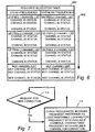
- Fig. 7 shows basic steps performed by resource allocation unit (RAU) 66 of radio network controller (RNC) 24 for the connection controlled mode of the invention.
- step 7-1 shows resource allocation unit (RAU) 66 waiting for a request for a new connection.
- resource allocation unit (RAU) 66 checks through resource allocation table 600, checking frequencies, in order, from the most preferred (e.g., frequency 1) to the least preferred (i.e., the maximum coverage frequency), looking for the first frequency that can be used for the new connection, and choosing this first frequency for this connection.
- the maximum coverage frequency is the most conserved frequency, and therefore utilized to reach user equipment units which are situated proximate the maximum perimeter P MAX of the cell (see Fig. 2C ).
- a more controlled (e.g., constant radius) service area for the cell can be obtained.
- the amount of traffic occurring on each frequency is monitored by the radio network controller (RNC) 22 and used as an estimate of the load or interference on each frequency.
- RNC radio network controller
- substantially all of the steps are performed by radio network controller (RNC) 24.
- the radio network controller (RNC) 24 obtains traffic measurements for each frequency.
- the person skilled in the art will appreciate that there are several ways for the RNC to obtain traffic measurements for a frequency, such as (for example) adding the number of connections in a sector (with a weighting factor for the case in which there are different types of connections).
- the radio network controller (RNC) 24 determines if the total traffic for the maximum coverage frequency (MCF) exceeds a first threshold, in similar manner to the interference determination of step 4-6 for the interference controlled mode. If the first threshold is exceeded at step 8-6, step 8 - 7 through step 8-9 are performed for the respective purposes of choosing a connection to reallocate from the maximum coverage frequency to another frequency, performing the actual reallocation (step 8-8), and setting the MCF protection flag (step 8-9), all before looping back to step 8-1. If the first traffic threshold is not exceeded at step 8-6, the radio network controller (RNC) 24 determines at step 8-10 whether the total traffic for the maximum coverage frequency is below a second threshold. If the determination at step 8-10 is positive, and if it is further determined at step 8-11 that the total traffic for the other frequency is high, a connection is allocated to the maximum coverage frequency at step 8-12.
- MCF maximum coverage frequency
- the person skilled in the art will realize that more than two uplink frequencies and more than two downlink frequencies can be employed at a given base station 22.
- multiple frequencies can be employed for sectorized base stations.
- the present invention is applicable even to sectorized base stations, there being a maximum coverage frequency for each sector.
- the maximum coverage frequency can be the same or different for each sector.
- the resource allocation unit (RAU) 66 can override the setting of the MCF protection flag and reallocate yet other connections in order to accommodate the emergency connection.
- having an appropriate allocation of traffic between the available plural frequencies utilized by the base station reduces cell breathing tendencies of the cell.
- the appropriate allocation of traffic between the different plural frequencies utilized at a base station can be made both when a new radio resource is to be allocated in a cell (e.g., a new connection is requested), as well as a reallocation of existing traffic from the maximum coverage frequency to another frequency when cell conditions so require.
- some frequency(ies) may carry more traffic so that other frequency(cies) [e.g., the maximum coverage frequency] can have reduced interference levels and thereby be used throughout the cell.
- the allocation of traffic in accordance with the present invention can be made according to differing strategies.
- One such strategy is to maximize the cell size, i.e., to minimize the interference level at the maximum coverage frequency.
- Another strategy can be to try to keep the cell size as constant as possible.
- These two strategies were merely examples, other strategies are within the purview of the present invention.
- These traffic allocation strategies can, of course, be combined with other mechanisms in order to reduce further the effect of cell breathing.
- the network of Fig. 1 may or may not include GPRS nodes.
- RNC physical radio network controller
- the functionality of the radio network controller (RNC) may instead be incorporated or otherwise included in another node such as the mobile switching center (MSC).
- MSC mobile switching center
- the embodiment of base station node 22 and radio network controller (RNC) node 24 described herein, e.g., with reference to Fig. 3 are merely examples.
- Other node architectures and functionalities occur in differing embodiments.
Abstract
Description
- The present invention pertains to cellular telecommunications, and particularly to maintaining sufficient cell size in a cellular telecommunications system.
- Cellular telecommunications systems employ a wireless link (e.g., air interface) between the (mobile) user equipment and a base station (BS). The base station has transmitters and receivers for radio connections with numerous mobile user equipment units. The mobile user equipment units can take the form of cellular telephones or laptop computers with mobile termination, for example. The effective geographical transmission/reception range of a base station defines a cell served by that base station. Thus, in a sense, the cell is the territory in which a user equipment unit can be located and still remain in radio communication over the air interface with the associated base station.
- In a cellular telecommunications network, the base stations are preferably situated so that the cells served thereby are slightly overlapping proximate their perimeters or at least contiguous, thereby permitting a user equipment unit to move from one cell to another cell and remain within the telecommunications network. For example, when a user equipment unit participating in a mobile connection (e.g., telephone call) moves from a first cell served by a first base station to a second cell served by a second base station, in some technologies a handoff or handover of the mobile connection occurs. As a result of the handoff or handover, the mobile connection is handled through the second base station rather than the first station as formerly.
- Radio coverage is a very important characteristic for all cellular telecommunication systems. Cell size is a major factor in obtaining good geographical coverage. The cell size is dependent upon the maximum allowed path loss between the user equipment unit and the base station. The greater the maximum allowed path loss, the further a user equipment unit can move away from the base station and still receive a sufficient signal. This means that if the maximum allowed path loss is increased, then the cell size is increased. Conversely, if the maximum allowed path loss is decreased, then the cell size is reduced.
- There are a variety of multiple access techniques for cellular telecommunications systems which permit cellular telecommunications resources to be available to large numbers of users. One multiple access technique which has gained recent interest is code division multiple access (CDMA). In a code division multiple access (CDMA) mobile telecommunications system, the information transmitted between a base station and a particular mobile station is modulated by a mathematical code (such as spreading code) to distinguish it from information for other mobile stations which are utilizing the same radio frequency. Thus, in CDMA, the individual radio links are discriminated on the basis of codes. Various aspects of CDMA are set forth in Garg, Vijay K. et al., Applications of CDMA in Wireless/Personal Communications, Prentice Hall (1997). Typically the same base band signal with suitable spreading is sent from several base stations with overlapping coverage. The mobile terminal can thus receive and use signals from several base stations simultaneously.
- In general, a CDMA base station attempts to maintain a sufficient Signal to Interference Ratio (SIR) in communications with each mobile station that it currently serves. To this end, a base station measures the received signal from each of the mobile stations in order to determine the Signal to Interference Ratio (SIR). For each mobile station, the SIR is compared with a target value SIR. If the SIR measured for a particular mobile station is less than the target value SIR, the base station commands the mobile station to increase its power in order that a stronger signal can be received at the base station. On the other hand, if the SIR determined for the particular station is greater than the target value SIR, the base station requests the mobile station to decrease its power. Thus, a power control loop is established between the base station and the mobile station, with an uplink aspect of the power control loop involving the mobile station transmitting to the base station and with the base station, upon receiving the signal from the mobile station and comprising the SINR for the station with the target SIR, providing power control commands to the mobile station as a downlink aspect of the power control loop. An example CDMA power loop control system is disclosed in United States Patent No.
6,154,450 entitled "Signaling Method for CDMA Quality Based Power Control". - Thus, in a CDMA system, when the number of active user equipment units increase in a cell, then the interference level also increases in the cell. Unfortunately, this increased interference level has a negative impact upon the maximum allowed path loss. That is, the increased interference level will also decrease cell size. The reduction of cell size due to an increased interference level produces an effect in a CDMA system commonly referred to as "cell breathing".
- The overall effect of cell breathing is that the cell size is reduced when the traffic is increased. Providing more cells (e.g., a more dense population of base stations) is one way of compensating for this undesirable reduction of cell size. However, there is expense and overhead in providing and operating additional base stations. Moreover, the provision of more cells may still result in varying cell coverage, e.g., cell breathing with respect even to the new cells.
-
WO 98/52364 - What is needed, therefore, and an object of the present invention, is a technique to reduce the effect of cell breathing in a telecommunications system.
- Traffic is allocated between plural radio frequencies utilized at a base station of a cellular telecommunications system according to a cell size strategy for a cell served by the base station. The traffic can be allocated between the plural frequencies utilized at the base station to maintain a cell size as having a predetermined coverage (e.g., to maximize cell size or maintain the cell size has having a predetermined geographical minimum), thereby reducing effects of cell breathing.
- In accordance with aspects of the invention, the base station is operated so that at least one of its plural frequencies can be utilized as far away as a geographically constant cell perimeter. In this regard, one of the plural frequencies utilized at the base station is selected as a maximum coverage frequency. The interference on the maximum coverage frequency is limited so that at least the maximum coverage frequency can be utilized throughout the cell, even to the constant cell perimeter.
- In one mode of the invention, known as the interference controlled mode, the total interference on the maximum coverage frequency is limited so that the maximum coverage frequency can be utilized at the furthermost extent of the cell. In this mode, total interference on the maximum coverage frequency is measured and, if the total interference exceeds a predetermined threshold, (1) one or more connections carried by the maximum coverage frequency is released (handed over) to another one of the plural frequencies, and/or (2) newly requesting connections are required to be carried on the other frequency(ies). In one example embodiment of this mode, the total interference measurement for the maximum coverage frequency is made at the base station. The base station transfers its total interference measurement for the maximum coverage frequency to its radio network controller (RNC). The radio network controller (RNC) compares the total interference for the maximum coverage frequency to a constant coverage threshold value for the base station. If the total interference for the maximum coverage frequency is within a first predetermined interval of the constant coverage threshold value, the radio network controller (RNC) realizes that the maximum coverage frequency requires protection. For such protection, a resource allocation unit in the radio network controller (RNC) can either (1) transfer existing connections from the maximum coverage frequency to the other frequency(ies), or (2) require that new connections utilize the frequency(ies) other than the maximum coverage frequency. Should the total interference for the maximum coverage frequency fall below a second predetermined interval of the constant coverage threshold value, the radio network controller (RNC) can suspend protection efforts for the maximum coverage frequency.
- In another mode, known as the connection controlled mode, the available frequencies are ordered in a list. The plural frequencies on the ordered list are ranked in a preferred order of usage with the maximum coverage frequency being the one that is used last (i.e., a least preferred frequency). In the connection controlled mode, when there is a new connection, the system tires to allocate according to the ordered list with the maximum coverage frequency being utilized only as a last resort. For the connection controlled mode, there is also the possibility also to limit the number of connections.
- In yet another mode, known as the traffic controlled mode, the amount of traffic occurring on each frequency is monitored and used as an estimate of the load or interference on each frequency. High traffic connections can be allocated to frequencies other than the maximum coverage frequency.
- The foregoing and other objects, features, and advantages of the invention will be apparent from the following more particular description of preferred embodiments as illustrated in the accompanying drawings in which reference characters refer to the same parts throughout the various views. The drawings are not necessarily to scale, emphasis instead being placed upon illustrating the principles of the invention.
-
Fig. 1 a schematic view of an embodiment of a telecommunications system which utilizes the present invention. -
Fig. 2A is a diagrammatic view of a cell. -
Fig. 2B is a diagrammatic view of a conventionally operated cell in a heavy traffic situation. -
Fig. 2C is a diagrammatic view of the cell ofFig. 2B operated in accordance with a mode of the present invention rather than conventionally. -
Fig. 3 is a schematic view of selected components of a base station node and a radio network controller (RNC) node, included in the telecommunications system ofFig. 1 , according to an embodiment of the present invention. -
Fig. 4 is a flowchart showing example basic steps performed in accordance with an interference controlled mode of the present invention. -
Fig. 5 is a diagrammatic view of an example format of a coverage assurance message according to an embodiment of the invention. -
Fig. 6 is a diagrammatic view of a resource allocation table used for a connection controlled mode of the invention. -
Fig. 7 is a flowchart showing example basic steps performed in accordance with a connection controlled mode of the present invention. -
Fig. 8 is a flowchart showing example basic steps performed in accordance with a traffic controlled mode of the present invention. - In the following description, for purposes of explanation and not limitation, specific details are set forth such as particular architectures, interfaces, techniques, etc. in order to provide a thorough understanding of the present invention. However, it will be apparent to those skilled in the art that the present invention may be practiced in other embodiments that depart from these specific details. In other instances, detailed descriptions of well known devices, circuits, and methods are omitted so as not to obscure the description of the present invention with unnecessary detail.
-
Fig. 1 shows atelecommunications network 18 in which auser equipment unit 20 communicates with one ormore base stations 22 over air interface (e.g., radio interface) 23.Base stations 22 are connected by terrestrial lines (or microwave) to radio network controller (RNC) 24 [also known as a base station controller (BSC) in some networks]. The radio network controller (RNC) 24 is, in turn, connected through a control node known as themobile switching center 26 to circuit-switched telephone networks (PSTN/ISDN) represented bycloud 28. In addition, radio network controller (RNC) 24 is connected to Serving GPRS Support Node (SGSN) 25 and throughbackbone network 27 to a Gateway GRPS support node (GGSN) 30, through which connection is made with packet-switched networks (e.g., the Internet, X.25 external networks) represented bycloud 32. - As understood by those skilled in the art, when
user equipment unit 20 participates in a mobile telephonic connection, signaling information and user information fromuser equipment unit 20 are transmitted overair interface 23 on designated radio channels to one or more of thebase stations 22. The base stations have radio transceivers which transmit and receive radio signals involved in the connection or session. For information on the uplink from theuser equipment unit 20 toward the other party involved in the connection, the base stations convert the radio-acquired information to digital signals which are forwarded to radio network controller (RNC) 24. The radio network controller (RNC) 24 orchestrates participation of theplural base stations 22 which may be involved in the connection or session, sinceuser equipment unit 20 may be geographically moving and handover may be occurring relative to thebase stations 22. On the uplink, radio network controller (RNC) 24 picks frames of user information from one ormore base stations 22 to yield a connection betweenuser equipment unit 20 and the other party, whether that party be in PSTN/IDSN 28 or on the packet-switched networks (e.g., the Internet) 32. - In the illustrated embodiment, since plural mobile stations served by
base station 22 can utilize the same radio frequencies, code division multiple access techniques are employed to distinguish between the various mobile stations. In fact, unless otherwise noted, as used herein the term "channel" refers to CDMA channel, which for any mobile station is defined in terms of an RF frequency and a particular code sequence. -
Fig. 2A shows a cell C served by a representative one of the base stations (which is identified simply as base station 22). Thebase station 22 and cell C are designed so that, under reasonable traffic conditions, a frequency utilized by base station 22 (either downlink or uplink frequency) is effective for connections with user equipment units located at a nominal radius RNOMINAL frombase station 22. As shown inFig. 2A , cell C has a nominal perimeter PNOMINAL. The "MS"s inFig. 2A represent locations of active user equipment units (e.g., mobile stations) in cell C. -
Fig. 2B illustrates a heavy traffic situation for cell C as conventionally operated. In accordance with conventional operation, there may be only one frequency utilized for each directional link with respect to base station 22 (e.g., only one frequency for the uplink and only one frequency for the downlink), or (if multiple frequencies are provided) no coordination between the multiple frequencies for sake of cell coverage.Fig. 2B shows cell C having many more user equipment units MSs being shown than inFig. 2A . In view of the interference occasioned by the increased traffic in cell C as shown inFig. 2C , the frequency utilized bybase station 22 is effective only to a distance REFFECTIVE shown inFig. 2B (REFFECTIVE < RNOMINAL). In essence, the conventional operation and cell breathing of cell C has reduced the coverage area of cell C, e.g., reduced the coverage area ofbase station 22. Consequentially, user equipment units MS positioned at a radius frombase station 22 greater than REFFECTIVE shown inFig. 2B cannot be served bybase station 22 under these heavy traffic conditions. - The present invention reduces effects of cell breathing in a manner illustrated, for example, in
Fig. 2C . In particular, in accordance with the present invention plural radio frequencies are utilized bybase station 22 for each directional link (e.g., plural frequencies for the uplink and plural frequencies for the downlink). As explained below, one of the plural frequencies is designated as a maximum coverage frequency. In essence, interference on the maximum coverage frequency is limited by allocation of traffic, when necessary, to another of the radio frequencies. The limiting of traffic (e.g., by reallocation to other frequency(ies)) keeps the maximum coverage frequency useable at the cell perimeter (assuming sufficient available channels). Thus, as shown inFig. 2C , the cell C as operated by the present invention has a maximum geographical cell perimeter PMAX (PMAX being greater than PEFFECTIVE). In order to reserve the maximum coverage frequency for use at perimeter PMAX, traffic may be allocated so that the maximum coverage frequency is allocated to user equipment units in the outer ring region as shown inFig. 2C . Other frequency(ies) are allocated to the remaining user equipment units (as shown by the inner ring region, which now has a radius smaller than REFFECTIVE ofFig. 2B ). Implementation of the frequency allocation scheme of the present invention is described in more detail below. -
Fig. 3 shows in more detail components, pertinent to the present invention, of anexample base station 22 node and an example radio network controller (RNC) 24 node.Base station 22 is connected by aphysical link 40 to radio network controller (RNC) 24.Physical link 40 is typically a terrestrial or microwave line. In the illustrated embodiment, link 40 carries data and signaling packets betweenbase station 22 and radio network controller (RNC) 24. Packets directed frombase station 22 to radio network controller (RNC) 24 are said to form anuplink 42 betweenbase station 22 and radio network controller (RNC) 24; packets directed from radio network controller (RNC) 24 tobase station 22 are said to form andownlink 44 betweenbase station 22 and radio network controller (RNC) 24. - As shown in
Fig. 3 ,base station 22 includesradio transceiver 501 andradio transceiver 502;node controller 52; and,network interface 54.Base station 22 serves cell C. In accordance with CDMA techniques, a particularuser equipment unit 20 in the cell is able to decode only the portion of the signal transmitted (from eithertransceiver 501 or transceiver 502) which has been encoded by the code known to that particular station. Similarly, the information transmitted by eachuser equipment unit 20 tobase station 22 is encoded with a unique code particular to that user equipment unit and recognizable bybase station 22 as being attributed to that station. The portion of a signal over which the code associated with a particular user equipment unit enables that user equipment unit to transmit or receive information relative tobase station 22 is known as a "channel" for that station. - In
base station 22,controller 52 conducts the coding and decoding of signals applied to and received fromradio transceiver 50. The signals encoded bycontroller 52 are primarily those obtained overlink 40 from radio network controller (RNC) 24. The signals decoded bycontroller 52 are primarily those destined for radio network controller (RNC) 24 overlink 40.Network interface 54 is connected betweencontroller 52 and link 40 in order to accommodate the transmission of signals betweenbase station 22 and radio network controller (RNC) 24. - Radio network controller (RNC) 24 has its
own network interface 60 connected to link 40.Network interface 60 is connected within radio network controller (RNC) 24 to diversity handoff (DHO)unit 62,node controller 64, and resource allocation unit (RAU) 66. Of considerable interest to the present invention are the functions performed by resource allocation unit (RAU) 66, which can include (for example) a microprocessor. - It should be noted, in passing, that the functions of radio network controller (RNC) 24 can also be performed by a type of node referred to as base station controller (BSC) or mobile switching center (MSC). Moreover, the radio network controller (RNC) 24 is typically connected to a plurality of base stations for performing operations such as those above-described. In addition, radio network controller (RNC) 24 is usually connected to one or more other radio network controllers comprising the mobile telecommunications network. At least one of the radio network controllers of the mobile telecommunications network is connected to or forms part of a gateway to the wired portion of the public switched telephone network (PSTN).
- Diversity handoff (DHO)
unit 62 performs numerous functions, including but not limited to assisting the transition which occurs when a mobile station travels or roams into a cell handled by another base station. In addition, diversity handoff (DHO)unit 62 computes a target signal to interference/noise ratio (TSNR) for each base station for which radio network controller (RNC) 24 is responsible. - The resource allocation unit (RAU) 66 of the embodiment of
Fig. 3 includes a resource allocation table 100. The resource allocation table 100 has a list or table of potential radio frequency resources, and reflects the status (already allocated or available) for each resource. The resources on the resource allocation table 100 are grouped by uplink and downlink. In the particular example of resource allocation table 100 shown inFig. 3 , the resource allocation table 100 includes two frequencies for the uplink and a corresponding two frequencies for the downlink. In other words, for this particular case there is one regular frequency pair and one maximum coverage frequency (MCF) pair. For each frequency the resource allocation table 100 has plural records, and in particular a record for each channel of the frequency. Thus, there are i number of records in resource allocation table 100 corresponding to i number of channels for the uplink regular frequency; i number of records in resource allocation table 100 corresponding to i number of channels for the downlink regular frequency; k number of records in resource allocation table 100 corresponding to k number of channels for the uplink maximum coverage frequency; and k number of records in resource allocation table 100 corresponding to k number of channels for the downlink maximum coverage frequency. Each record includes a status indication from which resource allocation unit (RAU) 66 can determine if the channel has already been allocated to a connection or remains available for a new connection. In addition, for each channel which has already been allocated to a connection, the record includes a connection identifier. - For sake of simplification, the resource allocation table 100 of
Fig. 3 is shown as having only two uplink frequencies and two downlink frequencies. It should be apparent that a greater number of uplink frequencies and two downlink frequencies can be employed. - As will become more evident below, in the embodiment of
Fig. 3 the total interference on the maximum coverage frequency (MCF) is limited so that the maximum coverage frequency is available for use by user equipment units proximate the maximum perimeter PMAX of the cell (seeFig. 2C ).Fig. 4 shows various basic steps or operations performed bybase station 22 and radio network controller (RNC) 24 in connection with theFig. 3 example embodiment of the invention. - At step 4-1, various signal measurements are performed by
base station 22. In this regard, when a connection involving a user equipment unit is in progress, the strength (i.e., received power) of the signal on the uplink from the user equipment unit tobase station 20 is monitored bybase station 20. Preferably, the strength of the signal on the uplink from the user equipment unit tobase station 20 is monitored essentially continuously bybase station 20. In this regard,radio transceiver 50 is interrogated bycontroller 52 with respect to each channel (e.g., each user equipment unit) to ascertain the received power of the signal. For each uplink frequency,controller 52 thus knows the received power for all user equipment units served by the uplink frequency ofbase station 20. For each frequency, including the maximum coverage frequency (MCF), the total interference is also measured. The person skilled in the art will appreciate that there are a number of ways that total interference for a frequency can be measured or ascertained, such as, e.g., using the total received power as an estimate of total interferences. Thus, at step 4-1 thecontroller 52 determines, with respect to each uplink frequency, both a signal strength for each channel and a total interference for the uplink frequency. - In passing, it is also noted that, with respect to each user equipment unit,
controller 52 also determines a signal to interference/noise ratio (SIR). - At step 4-2
controller 52 ofbase station 22 waits for a measurement time reporting interval. When it is time to report a measurement, at step 4-3 thecontroller 52 ofbase station 22 prepares a coverage assurance message (CAM). An example format of a coverage assurance message (CAM) is illustrated inFig. 5 . The coverage assurance message (CAM) begins with a header 5-1, which identifies, e.g., the type of message as being a coverage assurance message (CAM). The header is followed by a field 5-2 which declares the number of frequencies reported in the coverage assurance message (CAM). Field 5-3 declares the total interference for the uplink maximum coverage frequency. Field 5-4 states the number of channels active for the maximum coverage frequency. Fields 5-5-1 through 5-5-j give the signal strength for each of the active channels for the maximum coverage frequency. Similarly, field 5-6 declares the total interference for the uplink regular frequency (REGF). Field 5-7 states the number of channels active for the uplink regular frequency (REGF). Fields 5-8-1 through 5-8-q give the signal strength for each of the active channels for the uplink regular frequency (REGF). The values for total interference for each frequency, as well as the signal strength values for fields 5-5-1 through 5-5-j and fields 5-8-1 through 5-8-q, are obtained from step 4-1. - The format of the coverage assurance message (CAM) as illustrated in
Fig. 5 would have a value of "2" in the number of frequencies field 5-2 in order to reflect utilization on the uplink of both the maximum coverage frequency and the other uplink frequency (herein known as the regular frequency). It will be readily understood that, when resource allocation table 100 has more than two uplink frequencies, the coverage assurance message (CAM) also includes information for a corresponding number of more than two uplink frequencies. - At step 4-4 the
base station 22 is shown as transmitting the coverage assurance message (CAM) to radio network controller (RNC) 24 overlink 40. Thereafter, thecontroller 52 ofbase station 22 returns to step 4-2 to determine if it is time to report new measurement results (which are being essentially continuously taken at step 4-1). Upon expiration of a further measurement time reporting interval, a further coverage assurance message (CAM) will be prepared and transmitted, all as understood with respect to the foregoing discussion of step 4-3 and step 4-4. - In
Fig. 4 , a broken line delineates steps performed by base station 22 (on the left of the broken line) and steps performed by radio network controller (RNC) 24 (on the right of the broken line). The transmission of the coverage assurance message (CAM) is reflected by the arrow labeled "CAM". - Step 4-5 of
Fig. 4 shows radio network controller (RNC) 24 awaiting, and then processing (e.g., decoding), the coverage assurance message (CAM) received frombase station 22. Remaining functions performed by radio network controller (RNC) 24, and particularly by resource allocation unit (RAU) 66, with respect to the coverage assurance message (CAM) are illustrated as steps 4-6 through 4-12 inFig. 4 . - At step 4-6 the resource allocation unit (RAU) 66 determines whether the total interference value for the maximum coverage frequency exceeds a predetermined interference first threshold. As understood from
Fig. 5 , the total interference value for the maximum coverage frequency is obtained from field 5-3 of the coverage assurance message (CAM). If the interference first threshold is exceeded, step 4-7 through step 4-9 are performed. - At step 4-7, the resource allocation unit (RAU) 66 chooses an existing connection to be reallocated from the maximum coverage frequency to the other frequency (the regular frequency). In performing step 4-7, the resource allocation unit (RAU) 66 can note, from the records in resource allocation table 100, the connection identifier of an allocated channel for the uplink maximum coverage frequency, and change the connection from the maximum coverage frequency to a channel of the regular frequency. Such reallocation is accomplished by resource allocation unit (RAU) 66 at step 4-8. In addition, anticipating that addition of further connections would also cause the total interference level for the maximum coverage frequency to exceed the interference threshold, at step 4-9 the resource allocation unit (RAU) 66 sets a MCF protection flag. As long as the MCF protection flag is set, all requests for new connections must be allocated a channel of the regular frequency. In other words, when the MCF protection flag is set, the maximum coverage frequency cannot be used for new connections.
- If the interference first threshold is not exceeded at step 4-6, the resource allocation unit (RAU) 66 determines at step 4-10 whether the total interference value for the maximum coverage frequency is below a predetermined interference second threshold. If the total interference value for the maximum coverage frequency is below the predetermined interference second threshold, the resource allocation unit (RAU) 66 can determine whether further connections should be added to the maximum coverage frequency. In such case, resource allocation unit (RAU) 66 performs step 4-11 and step 4-12.
- At step 4-11, resource allocation unit (RAU) 66 checks the total interference value for the other frequency (e.g., the regular frequency). In the
Fig. 3 embodiment, this total interference value is obtained from field 5-6 of the coverage assurance message (CAM) ofFig. 5 . If it is determined at step 4-11 that the total interference value for the other frequency (e.g., the regular frequency) is high, then at step 4-12 resource allocation unit (RAU) 66 allocates a connection from the regular frequency to the maximum coverage frequency. The allocation is performed by consulting the resource allocation table 100, and determining therefrom a connection which can be transferred from the regular frequency to the maximum coverage frequency. - In the event that the total interference value for the maximum coverage frequency is below the predetermined interference second threshold (see step 4-10), or should the total interference for the regular frequency not be high (see step 4-11), and upon completion of any of step 4-9 and step 4-12, the resource allocation unit (RAU) 66 returns to step 4-5 to await the next coverage assurance message (CAM) issued by
base station 22. - Thus, the steps of
Fig. 4 depict an interference controlled mode of operation of resource allocation unit (RAU) 66, wherein the total interference on the uplink maximum coverage frequency is limited to be below the interference first threshold (see step 4-6). - Insofar as the downlink is concerned, coverage is primarily determined by the available Multiple Carrier Power Amplifier (MCPA) output power. A MCPA can be viewed as a common amplifier that serves a number of mobile units and thus is a pooled resource. The MCPA facilitates allocating a higher power to a mobile further away and a lower power for a mobile closer to the base station so long as the total allocated power does not exceed the MCPA power. This has the overall effect that at all reasonable loads the coverage will be uplink limited. Accordingly, interference increase does not have the same effect as on the uplink.
- Furthermore, most commonly each uplink frequency will have its corresponding downlink frequency, and one therefore often talks about a frequency allocation with the implicit meaning of one uplink frequency and the corresponding downlink frequency. Regarding the interference controlled mode, only the uplink interference has been included, so for that mode the most natural is to have a maximum coverage frequency based on the uplink measurements and together with this use the corresponding downlink frequency.
- In accordance with another mode of the invention, known as the connection controlled mode, the maximum coverage frequency (MCF) is used only as a last resort for allocation to a new connection. In the connection controlled mode, the resource allocation table 100 is conceptualized as being an ordered list of frequencies.
Fig. 6 shows another example of resource allocation table, particularly resource allocation table 600 which can be utilized with the resource allocation unit (RAU) 66 and other components shown inFig. 3 . For purposes of illustration, resource allocation table 600 is shown as having four uplink frequencies and four downlink frequencies. As reflected byarrow 602 inFig. 6 , the plural frequencies on the ordered list are ranked in preferred order of usage with the maximum coverage frequency being a least preferred frequency. In general, in the connection controlled mode, a new connection is allocated to a most preferred one of the plural frequencies having an available channel. -
Fig. 7 shows basic steps performed by resource allocation unit (RAU) 66 of radio network controller (RNC) 24 for the connection controlled mode of the invention. In particular, step 7-1 shows resource allocation unit (RAU) 66 waiting for a request for a new connection. When a request for a new connection is received, at step 7-2 resource allocation unit (RAU) 66 checks through resource allocation table 600, checking frequencies, in order, from the most preferred (e.g., frequency 1) to the least preferred (i.e., the maximum coverage frequency), looking for the first frequency that can be used for the new connection, and choosing this first frequency for this connection. Thus, the maximum coverage frequency is the most conserved frequency, and therefore utilized to reach user equipment units which are situated proximate the maximum perimeter PMAX of the cell (seeFig. 2C ). - Additionally, by not allowing more than a predetermined number of connections on the most conserved frequency, a more controlled (e.g., constant radius) service area for the cell can be obtained.
- In accordance with yet a further mode of the invention, known as the traffic controlled mode, the amount of traffic occurring on each frequency is monitored by the radio network controller (RNC) 22 and used as an estimate of the load or interference on each frequency. In an example of the traffic controlled mode illustrated in
Fig. 8 , substantially all of the steps are performed by radio network controller (RNC) 24. As reflected by step 8-1, the radio network controller (RNC) 24 obtains traffic measurements for each frequency. The person skilled in the art will appreciate that there are several ways for the RNC to obtain traffic measurements for a frequency, such as (for example) adding the number of connections in a sector (with a weighting factor for the case in which there are different types of connections). As a next step (step 8-6), the radio network controller (RNC) 24 determines if the total traffic for the maximum coverage frequency (MCF) exceeds a first threshold, in similar manner to the interference determination of step 4-6 for the interference controlled mode. If the first threshold is exceeded at step 8-6, step 8 - 7 through step 8-9 are performed for the respective purposes of choosing a connection to reallocate from the maximum coverage frequency to another frequency, performing the actual reallocation (step 8-8), and setting the MCF protection flag (step 8-9), all before looping back to step 8-1. If the first traffic threshold is not exceeded at step 8-6, the radio network controller (RNC) 24 determines at step 8-10 whether the total traffic for the maximum coverage frequency is below a second threshold. If the determination at step 8-10 is positive, and if it is further determined at step 8-11 that the total traffic for the other frequency is high, a connection is allocated to the maximum coverage frequency at step 8-12. - Although not particularly stated herein, the person skilled in the art will realize that more than two uplink frequencies and more than two downlink frequencies can be employed at a given
base station 22. In fact, as well known in the art, multiple frequencies can be employed for sectorized base stations. The present invention is applicable even to sectorized base stations, there being a maximum coverage frequency for each sector. The maximum coverage frequency can be the same or different for each sector. - It should be noted, in connection with the setting of the MCF protection flag at step 4-9, that for requests for certain important connections (e.g., such as a request for an emergency connection [e.g., 911]), the resource allocation unit (RAU) 66 can override the setting of the MCF protection flag and reallocate yet other connections in order to accommodate the emergency connection.
- Thus, in accordance with the present invention, having an appropriate allocation of traffic between the available plural frequencies utilized by the base station reduces cell breathing tendencies of the cell. Moreover, as explained above, the appropriate allocation of traffic between the different plural frequencies utilized at a base station can be made both when a new radio resource is to be allocated in a cell (e.g., a new connection is requested), as well as a reallocation of existing traffic from the maximum coverage frequency to another frequency when cell conditions so require. As a consequence of the allocation (or reallocation), some frequency(ies) may carry more traffic so that other frequency(cies) [e.g., the maximum coverage frequency] can have reduced interference levels and thereby be used throughout the cell.
- As exemplified above, the allocation of traffic in accordance with the present invention can be made according to differing strategies. One such strategy is to maximize the cell size, i.e., to minimize the interference level at the maximum coverage frequency. Another strategy can be to try to keep the cell size as constant as possible. These two strategies were merely examples, other strategies are within the purview of the present invention. These traffic allocation strategies can, of course, be combined with other mechanisms in order to reduce further the effect of cell breathing.
- Various embodiments described herein and illustrated in the drawings are only examples. For example, the network of
Fig. 1 may or may not include GPRS nodes. There is also the possibility that there may be no separate physical radio network controller (RNC) node, e.g., the functionality of the radio network controller (RNC) may instead be incorporated or otherwise included in another node such as the mobile switching center (MSC). Moreover, as noted above, the embodiment ofbase station node 22 and radio network controller (RNC)node 24 described herein, e.g., with reference toFig. 3 , are merely examples. Other node architectures and functionalities occur in differing embodiments. - While the invention has been described in connection with what is presently considered to be the most practical and preferred embodiment, it is to be understood that the invention is not to be limited to the disclosed embodiment, but on the contrary, is intended to cover various modifications and equivalent arrangements included within the scope of the appended claims.
Claims (19)
- A method of operating a cellular telecommunications system (18) wherein user equipment units in a cell served by a base station can interfere, the method characterized by allocating traffic between plural radio frequencies utilized at the base station (22) according to a cell size strategy for the cell to maintain or maximize cell size.
- The method of claim 1, comprising allocating traffic between the plural frequencies utilized at the base station (22) to maintain a cell size as having a predetermined coverage (Pmax).
- The method of claim 1, comprising allocating traffic between the plural frequencies utilized at the base station to maximize cell size.
- The method of claim 1, further comprising:designating one of the plural frequencies as a maximum coverage frequency;measuring total interference on the maximum coverage frequency; and,when the total interference on the maximum coverage frequency exceeds an interference first threshold, releasing a connection carried by the maximum coverage frequency to another one of the plural frequencies.
- The method of claim 1, further comprising:designating one of the plural of frequencies as a maximum coverage frequency;measuring total interference on the maximum coverage frequency; and,when the total interference on the maximum coverage frequency exceeds an interference first threshold, requiring another one of the plural frequencies to carry a newly requested connection.
- The method of claim 1, further comprising:designating one of the plural frequencies as a maximum coverage frequency;limiting a number of connections allocated to the maximum coverage frequency whereby the maximum coverage frequency is utilizable proximate an edge of the cell.
- The method of claim 1, further comprising:designating one of the plural frequencies as a maximum coverage frequency;maintaining an ordered list of the plural frequencies, the plural frequencies on the ordered list being ranked in preferred order of usage with the maximum coverage frequency being a least preferred frequency ;allocating to a new connection a most preferred one of the plural frequencies having an available channel.
- The method of claim 1, further comprising:designating one of the plural frequencies as a maximum coverage frequency;limiting an amount of traffic allocated to the maximum coverage frequency whereby the maximum coverage frequency is utilizable proximate an edge of the cell.
- The method of claim 1, further comprising:designating one of the plural frequencies as a maximum coverage frequency;determining total traffic on the maximum coverage frequency; andwhen the total traffic on the maximum coverage frequency exceeds a first traffic threshold, requiring another one of the plural frequencies to carry a connection.
- A cellular telecommunications system (18) wherein user equipment units in a cell served by a base station can interfere, the system (18) comprising:a base station (22) adapted to utilize plural radio frequencies for serving a cell;a resource allocation unit (66) adapted to allocate traffic between the plural radio frequencies according to a cell size strategy for the cell to maintain or maximize cell size.
- The system of claim 10, wherein the resource allocation unit (66) is adapted to allocate traffic between the plural frequencies utilized at the base station to maintain a cell size as having a predetermined coverage (Pmax).
- The system of claim 10, wherein the resource allocation unit is adapted to allocate traffic between the plural frequencies utilized at the base station to maximize cell size.
- The system of claim 10, wherein one of the plural radio frequencies is designated as a maximum coverage frequency, wherein the base station is adapted to measure total interference on the maximum coverage frequency; and further comprising
a node (24) which is adapted to release a connection carried by the maximum coverage frequency to another one of the plural frequencies when the total interference on the maximum coverage frequency exceeds a predetermined threshold. - The system of claim 13, wherein the node that is adapted to release the connection carried by the maximum coverage frequency is a radio network controller (24).
- The system of claim 10, wherein one of the plural radio frequencies is designated as a maximum coverage frequency, wherein the base station is adapted to measure total interference on the maximum coverage frequency; and further comprising
a node (24) which is adapted to require another one of the plural frequencies to carry a newly requested connection when the total interference on the maximum coverage frequency exceeds a predetermined threshold. - The system of claim 15, wherein the node which is adapted to require another one of the plural frequencies to carry a newly requested connection is a radio network controller (24).
- The system of claim 10, wherein one of the plural radio frequencies is designated as a maximum coverage frequency, wherein the resource allocation unit (66) is adapted to limit a number of connections allocated to the maximum coverage frequency whereby the maximum coverage frequency is utilizable proximate an edge of the cell.
- The system of claim 17, wherein the resource allocation unit is adapted to maintain an ordered list (100) of the plural frequencies, the plural frequencies on the ordered list being ranked in preferred order of usage with the maximum coverage frequency being a least preferred frequency, and wherein the resource allocation unit is adapted to allocate to a new connection a most preferred one of the plural frequencies having an available channel.
- The system of claim 10, whereon one of the plural radio frequencies is designated as a maximum coverage frequency, wherein the resource allocation unit is adapted to determine total traffic on the maximum coverage frequency, and wherein when the total traffic on the maximum coverage frequency exceeds a traffic threshold, the resource allocation unit is adapted to require another one of the plural frequencies to carry a connection.
Applications Claiming Priority (3)
| Application Number | Priority Date | Filing Date | Title |
|---|---|---|---|
| US38537599A | 1999-08-30 | 1999-08-30 | |
| US385375 | 1999-08-30 | ||
| PCT/SE2000/001654 WO2001017300A1 (en) | 1999-08-30 | 2000-08-29 | Cell breathing reduction in a cellular network |
Publications (2)
| Publication Number | Publication Date |
|---|---|
| EP1212909A1 EP1212909A1 (en) | 2002-06-12 |
| EP1212909B1 true EP1212909B1 (en) | 2008-07-16 |
Family
ID=23521146
Family Applications (1)
| Application Number | Title | Priority Date | Filing Date |
|---|---|---|---|
| EP00959079A Expired - Lifetime EP1212909B1 (en) | 1999-08-30 | 2000-08-29 | Cell breathing reduction in a cellular network |
Country Status (10)
| Country | Link |
|---|---|
| EP (1) | EP1212909B1 (en) |
| JP (1) | JP2003508989A (en) |
| CN (1) | CN1237834C (en) |
| AR (1) | AR025863A1 (en) |
| AT (1) | ATE401753T1 (en) |
| AU (1) | AU777818B2 (en) |
| DE (1) | DE60039522D1 (en) |
| MX (1) | MXPA02002089A (en) |
| TW (1) | TW493355B (en) |
| WO (1) | WO2001017300A1 (en) |
Families Citing this family (6)
| Publication number | Priority date | Publication date | Assignee | Title |
|---|---|---|---|---|
| EP1679933B1 (en) * | 2003-09-30 | 2009-07-01 | Mitsubishi Denki K.K. | Mobile communication system for controlling communication mode |
| EP1670266B1 (en) | 2003-09-30 | 2009-07-01 | Mitsubishi Denki Kabushiki Kaisha | Communication mode control method |
| JP4978084B2 (en) * | 2006-07-05 | 2012-07-18 | 日本電気株式会社 | Cellular system, frequency carrier allocation method thereof, base station controller and base station used therefor |
| CN101128011B (en) * | 2007-09-19 | 2012-05-23 | 中兴通讯股份有限公司 | A method for automatic cell interference optimization |
| KR100995903B1 (en) | 2007-12-13 | 2010-11-23 | 주식회사 케이티 | Method for managing radio resource in mobile communication system and system thereof |
| TWI524799B (en) * | 2010-10-12 | 2016-03-01 | 內數位專利控股公司 | Service-based approach to channel selection and network configuration for television white space networks |
Family Cites Families (4)
| Publication number | Priority date | Publication date | Assignee | Title |
|---|---|---|---|---|
| JP3110202B2 (en) * | 1993-04-21 | 2000-11-20 | 日本電気通信システム株式会社 | Frequency reuse method |
| FI952429A (en) * | 1995-05-18 | 1996-11-19 | Nokia Telecommunications Oy | Capacity increase in a cellular cellular network |
| US5946625A (en) * | 1996-10-10 | 1999-08-31 | Ericsson, Inc. | Method for improving co-channel interference in a cellular system |
| US5953661A (en) * | 1997-05-16 | 1999-09-14 | Nextel Communications | Method of maximizing spectral efficiency in a cellular communications system |
-
2000
- 2000-08-25 TW TW089117235A patent/TW493355B/en not_active IP Right Cessation
- 2000-08-29 WO PCT/SE2000/001654 patent/WO2001017300A1/en active IP Right Grant
- 2000-08-29 JP JP2001521110A patent/JP2003508989A/en active Pending
- 2000-08-29 AR ARP000104498A patent/AR025863A1/en unknown
- 2000-08-29 AT AT00959079T patent/ATE401753T1/en not_active IP Right Cessation
- 2000-08-29 DE DE60039522T patent/DE60039522D1/en not_active Expired - Lifetime
- 2000-08-29 CN CN00815065.6A patent/CN1237834C/en not_active Expired - Fee Related
- 2000-08-29 EP EP00959079A patent/EP1212909B1/en not_active Expired - Lifetime
- 2000-08-29 MX MXPA02002089A patent/MXPA02002089A/en active IP Right Grant
- 2000-08-29 AU AU70463/00A patent/AU777818B2/en not_active Ceased
Also Published As
| Publication number | Publication date |
|---|---|
| CN1237834C (en) | 2006-01-18 |
| EP1212909A1 (en) | 2002-06-12 |
| DE60039522D1 (en) | 2008-08-28 |
| JP2003508989A (en) | 2003-03-04 |
| AR025863A1 (en) | 2002-12-18 |
| TW493355B (en) | 2002-07-01 |
| AU7046300A (en) | 2001-03-26 |
| AU777818B2 (en) | 2004-11-04 |
| WO2001017300A1 (en) | 2001-03-08 |
| CN1391775A (en) | 2003-01-15 |
| ATE401753T1 (en) | 2008-08-15 |
| MXPA02002089A (en) | 2002-09-18 |
Similar Documents
| Publication | Publication Date | Title |
|---|---|---|
| CN100375564C (en) | System and method for estimating interfrequency measurements used for radio network | |
| JP3066327B2 (en) | Code division multiple access system | |
| US5491717A (en) | Method for controlling transmission during handoff in a communication system | |
| US10009134B2 (en) | Method and apparatus for scheduling dedicated transmissions in response to interference levels at neighboring base stations | |
| US5548808A (en) | Method for performing a handoff in a communication system | |
| CA2322296C (en) | Telecommunications inter-exchange measurement transfer | |
| US6363252B1 (en) | Advanced method for executing handover | |
| US6539227B1 (en) | Methods and systems for controlling hard and soft handoffs in radio communications systems | |
| EP1179961B1 (en) | A method for optimizing a number of communication links | |
| EP1675427A1 (en) | Cell selection and inter-frequency handover | |
| CN110870346B (en) | Apparatus and method for base station load distribution in wireless communication system | |
| AU689055B2 (en) | Method and apparatus for maintaining call quality in a communication system | |
| EP1452065B1 (en) | A method and arrangement for allocation the quantity of a channel to a mobile station as a function of the measured quality | |
| KR101123587B1 (en) | Distributed resource management for enhanced dedicated channel | |
| KR20000071572A (en) | System and method for prevention of reverse jamming due to link imbalance in wireless communication systems | |
| US7319883B2 (en) | Method and apparatus for determining a transmit power | |
| WO1992011736A1 (en) | Quality check for a mobile cellular radio system | |
| US20050239472A1 (en) | Allocation method and controller | |
| EP1212909B1 (en) | Cell breathing reduction in a cellular network | |
| JP2921739B2 (en) | Call admission control method and apparatus | |
| KR100198954B1 (en) | Method of allocating channel of cdma system in highway |
Legal Events
| Date | Code | Title | Description |
|---|---|---|---|
| PUAI | Public reference made under article 153(3) epc to a published international application that has entered the european phase |
Free format text: ORIGINAL CODE: 0009012 |
|
| 17P | Request for examination filed |
Effective date: 20020325 |
|
| AK | Designated contracting states |
Kind code of ref document: A1 Designated state(s): AT BE CH CY DE DK ES FI FR GB GR IE IT LI LU MC NL PT SE |
|
| AX | Request for extension of the european patent |
Free format text: AL;LT;LV;MK;RO;SI |
|
| RAP1 | Party data changed (applicant data changed or rights of an application transferred) |
Owner name: TELEFONAKTIEBOLAGET LM ERICSSON (PUBL) |
|
| GRAP | Despatch of communication of intention to grant a patent |
Free format text: ORIGINAL CODE: EPIDOSNIGR1 |
|
| GRAS | Grant fee paid |
Free format text: ORIGINAL CODE: EPIDOSNIGR3 |
|
| GRAA | (expected) grant |
Free format text: ORIGINAL CODE: 0009210 |
|
| AK | Designated contracting states |
Kind code of ref document: B1 Designated state(s): AT BE CH CY DE DK ES FI FR GB GR IE IT LI LU MC NL PT SE |
|
| REG | Reference to a national code |
Ref country code: GB Ref legal event code: FG4D |
|
| REG | Reference to a national code |
Ref country code: CH Ref legal event code: EP |
|
| REF | Corresponds to: |
Ref document number: 60039522 Country of ref document: DE Date of ref document: 20080828 Kind code of ref document: P |
|
| REG | Reference to a national code |
Ref country code: IE Ref legal event code: FG4D |
|
| PG25 | Lapsed in a contracting state [announced via postgrant information from national office to epo] |
Ref country code: PT Free format text: LAPSE BECAUSE OF FAILURE TO SUBMIT A TRANSLATION OF THE DESCRIPTION OR TO PAY THE FEE WITHIN THE PRESCRIBED TIME-LIMIT Effective date: 20081216 Ref country code: ES Free format text: LAPSE BECAUSE OF FAILURE TO SUBMIT A TRANSLATION OF THE DESCRIPTION OR TO PAY THE FEE WITHIN THE PRESCRIBED TIME-LIMIT Effective date: 20081027 |
|
| PG25 | Lapsed in a contracting state [announced via postgrant information from national office to epo] |
Ref country code: AT Free format text: LAPSE BECAUSE OF FAILURE TO SUBMIT A TRANSLATION OF THE DESCRIPTION OR TO PAY THE FEE WITHIN THE PRESCRIBED TIME-LIMIT Effective date: 20080716 Ref country code: FI Free format text: LAPSE BECAUSE OF FAILURE TO SUBMIT A TRANSLATION OF THE DESCRIPTION OR TO PAY THE FEE WITHIN THE PRESCRIBED TIME-LIMIT Effective date: 20080716 |
|
| PG25 | Lapsed in a contracting state [announced via postgrant information from national office to epo] |
Ref country code: BE Free format text: LAPSE BECAUSE OF FAILURE TO SUBMIT A TRANSLATION OF THE DESCRIPTION OR TO PAY THE FEE WITHIN THE PRESCRIBED TIME-LIMIT Effective date: 20080716 Ref country code: MC Free format text: LAPSE BECAUSE OF NON-PAYMENT OF DUE FEES Effective date: 20080831 |
|
| REG | Reference to a national code |
Ref country code: CH Ref legal event code: PL |
|
| PG25 | Lapsed in a contracting state [announced via postgrant information from national office to epo] |
Ref country code: DK Free format text: LAPSE BECAUSE OF FAILURE TO SUBMIT A TRANSLATION OF THE DESCRIPTION OR TO PAY THE FEE WITHIN THE PRESCRIBED TIME-LIMIT Effective date: 20080716 |
|
| PLBE | No opposition filed within time limit |
Free format text: ORIGINAL CODE: 0009261 |
|
| STAA | Information on the status of an ep patent application or granted ep patent |
Free format text: STATUS: NO OPPOSITION FILED WITHIN TIME LIMIT |
|
| 26N | No opposition filed |
Effective date: 20090417 |
|
| GBPC | Gb: european patent ceased through non-payment of renewal fee |
Effective date: 20081016 |
|
| PG25 | Lapsed in a contracting state [announced via postgrant information from national office to epo] |
Ref country code: CH Free format text: LAPSE BECAUSE OF NON-PAYMENT OF DUE FEES Effective date: 20080831 Ref country code: LI Free format text: LAPSE BECAUSE OF NON-PAYMENT OF DUE FEES Effective date: 20080831 |
|
| REG | Reference to a national code |
Ref country code: FR Ref legal event code: ST Effective date: 20090630 |
|
| PG25 | Lapsed in a contracting state [announced via postgrant information from national office to epo] |
Ref country code: IE Free format text: LAPSE BECAUSE OF NON-PAYMENT OF DUE FEES Effective date: 20080829 |
|
| PG25 | Lapsed in a contracting state [announced via postgrant information from national office to epo] |
Ref country code: IT Free format text: LAPSE BECAUSE OF FAILURE TO SUBMIT A TRANSLATION OF THE DESCRIPTION OR TO PAY THE FEE WITHIN THE PRESCRIBED TIME-LIMIT Effective date: 20080716 |
|
| PG25 | Lapsed in a contracting state [announced via postgrant information from national office to epo] |
Ref country code: FR Free format text: LAPSE BECAUSE OF NON-PAYMENT OF DUE FEES Effective date: 20080901 |
|
| PG25 | Lapsed in a contracting state [announced via postgrant information from national office to epo] |
Ref country code: GB Free format text: LAPSE BECAUSE OF NON-PAYMENT OF DUE FEES Effective date: 20081016 |
|
| PG25 | Lapsed in a contracting state [announced via postgrant information from national office to epo] |
Ref country code: SE Free format text: LAPSE BECAUSE OF FAILURE TO SUBMIT A TRANSLATION OF THE DESCRIPTION OR TO PAY THE FEE WITHIN THE PRESCRIBED TIME-LIMIT Effective date: 20081016 |
|
| PG25 | Lapsed in a contracting state [announced via postgrant information from national office to epo] |
Ref country code: LU Free format text: LAPSE BECAUSE OF NON-PAYMENT OF DUE FEES Effective date: 20080829 Ref country code: CY Free format text: LAPSE BECAUSE OF FAILURE TO SUBMIT A TRANSLATION OF THE DESCRIPTION OR TO PAY THE FEE WITHIN THE PRESCRIBED TIME-LIMIT Effective date: 20080716 |
|
| PG25 | Lapsed in a contracting state [announced via postgrant information from national office to epo] |
Ref country code: GR Free format text: LAPSE BECAUSE OF FAILURE TO SUBMIT A TRANSLATION OF THE DESCRIPTION OR TO PAY THE FEE WITHIN THE PRESCRIBED TIME-LIMIT Effective date: 20081017 |
|
| PGFP | Annual fee paid to national office [announced via postgrant information from national office to epo] |
Ref country code: NL Payment date: 20140826 Year of fee payment: 15 Ref country code: DE Payment date: 20140827 Year of fee payment: 15 |
|
| REG | Reference to a national code |
Ref country code: DE Ref legal event code: R119 Ref document number: 60039522 Country of ref document: DE |
|
| REG | Reference to a national code |
Ref country code: NL Ref legal event code: MM Effective date: 20150901 |
|
| PG25 | Lapsed in a contracting state [announced via postgrant information from national office to epo] |
Ref country code: NL Free format text: LAPSE BECAUSE OF NON-PAYMENT OF DUE FEES Effective date: 20150901 |
|
| PG25 | Lapsed in a contracting state [announced via postgrant information from national office to epo] |
Ref country code: DE Free format text: LAPSE BECAUSE OF NON-PAYMENT OF DUE FEES Effective date: 20160301 |