EP1211914A2 - Heating apparatus supplying a heat source other than microwave in a microwave oven - Google Patents
Heating apparatus supplying a heat source other than microwave in a microwave oven Download PDFInfo
- Publication number
- EP1211914A2 EP1211914A2 EP01403033A EP01403033A EP1211914A2 EP 1211914 A2 EP1211914 A2 EP 1211914A2 EP 01403033 A EP01403033 A EP 01403033A EP 01403033 A EP01403033 A EP 01403033A EP 1211914 A2 EP1211914 A2 EP 1211914A2
- Authority
- EP
- European Patent Office
- Prior art keywords
- heater
- cooking chamber
- air
- cooking
- ventilating fan
- Prior art date
- Legal status (The legal status is an assumption and is not a legal conclusion. Google has not performed a legal analysis and makes no representation as to the accuracy of the status listed.)
- Granted
Links
- 238000010438 heat treatment Methods 0.000 title claims abstract description 46
- 238000010411 cooking Methods 0.000 claims abstract description 83
- 238000007599 discharging Methods 0.000 claims abstract description 5
- 238000009434 installation Methods 0.000 description 6
- 238000004519 manufacturing process Methods 0.000 description 3
- 230000015556 catabolic process Effects 0.000 description 1
- 238000010276 construction Methods 0.000 description 1
- 238000006731 degradation reaction Methods 0.000 description 1
- 230000005611 electricity Effects 0.000 description 1
- 230000004048 modification Effects 0.000 description 1
- 238000012986 modification Methods 0.000 description 1
- 238000004904 shortening Methods 0.000 description 1
- 238000002834 transmittance Methods 0.000 description 1
Images

Classifications
-
- F—MECHANICAL ENGINEERING; LIGHTING; HEATING; WEAPONS; BLASTING
- F24—HEATING; RANGES; VENTILATING
- F24C—DOMESTIC STOVES OR RANGES ; DETAILS OF DOMESTIC STOVES OR RANGES, OF GENERAL APPLICATION
- F24C7/00—Stoves or ranges heated by electric energy
-
- H—ELECTRICITY
- H05—ELECTRIC TECHNIQUES NOT OTHERWISE PROVIDED FOR
- H05B—ELECTRIC HEATING; ELECTRIC LIGHT SOURCES NOT OTHERWISE PROVIDED FOR; CIRCUIT ARRANGEMENTS FOR ELECTRIC LIGHT SOURCES, IN GENERAL
- H05B6/00—Heating by electric, magnetic or electromagnetic fields
- H05B6/64—Heating using microwaves
- H05B6/647—Aspects related to microwave heating combined with other heating techniques
- H05B6/6482—Aspects related to microwave heating combined with other heating techniques combined with radiant heating, e.g. infrared heating
- H05B6/6485—Aspects related to microwave heating combined with other heating techniques combined with radiant heating, e.g. infrared heating further combined with convection heating
Definitions
- the present invention relates to a microwave oven, and more particularly, to a heating apparatus of a microwave oven for supplying a heat source other than microwave to a cooking chamber.
- the microwave oven generates microwave by using electricity.
- the microwave infiltrate into a cooking object, a molecule movement is made in the cooking object, according to which the food stuff is heated.
- a heating apparatus is additionally installed to heat foodstuff by using other heating source than microwave.
- Figure 1 is a view showing the construction of a microwave oven having a heat apparatus in accordance with a conventional art.
- the conventional microwave oven includes: a cooking chamber 102 for receiving a cooking object; a tray 104 installed at a lower portion of the cooking chamber 102, being rotated with foodstuff placed thereon; a magnetron (not shown) mounted at one side of the cooking chamber 102, for generating microwave for heating foodstuff; and a heating apparatus for providing a heat source required for heating foodstuff other than microwave generated from the magnetron.
- the heating apparatus includes a first heating system for providing a convection heat and a second heating system for providing a radiant heat, to provide a heat energy suitable to the kind or the property of the cooking object.
- the first heating system includes a convection heater 106 disposed at a rear side of the cooking chamber 102 and heating air; and a ventilating fan 108 disposed at the center of the convection heater 106 and circulating the air inside the cooking chamber 102 to pass the convection heater 106.
- the ventilating fan 108 when the ventilating fan 108 is driven, the air of the cooking chamber is sucked through the suction hole 112, and the sucked air is heated while passing the convection heater 106 and again supplied into the cooking chamber 102 through the discharge hole 114.
- the second heating system includes a grill heater 118 disposed at certain intervals at the upper portion of the cooking chamber 102, for generating a radiant heat to directly heat the cooking object.
- the cooking object is heated by a radiant heat generated from the grill heater 118 mounted at the upper portion of the cooking chamber.
- the installation space is much occupied, enlarging the size of the whole system, and since components are additionally required, its production cost is increased according to the increase in the number of components.
- Another object of the present invention is to provide a heating apparatus of a microwave oven that is capable of improving a heat efficiency as air is circulated vertically from the center of a cooking chamber in case of using radiant heat, and capable of improving a cooking quality of a cooking object and shortening the cooking speed by evenly transmitting heat to the cooking object.
- a heating apparatus of a microwave oven including: an upper plate installed at an upper portion of a cooking chamber into which a cooking object is to be received, having a suction hole for sucking air inside the cooking chamber and a discharge hole for discharging air; a first heater installed at the discharge hole side of the upper plate, for generating a convection heat; a second heater disposed in the same space as that of the first heater, for generating a radiant heat; and a ventilating fan installed at an upper portion of a region where the suction hole of the upper plate is formed, for circulating air inside the cooking chamber through the first and the second heaters.
- the heating apparatus of a microwave oven of the present invention further includes an air guide fixed to cover the ventilating fan and the first and the second heaters at the upper side of the upper plate, for guiding air flow from the ventilating fan to the first and the second heaters.
- the heating apparatus of a microwave oven of the present invention further includes a heater housing in which the first and the second heater are inserted and an air passage is formed at its upper side to supply air from the ventilating fan to the first and the second heaters.
- both ends of the first heater are fixed at the heater housing, and the first heater is formed in a bar type bent for several times to enlarge the area that air passes.
- the second heater is disposed at the upper side of the first heater with a certain distance therebetween, of which both ends are fixed at the heater housing.
- Figure 2 is a schematic sectional view showing a microwave oven having a heating apparatus in accordance with a preferred embodiment of the present invention
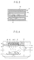
- Figure 3 is a front view showing a heater installation structure of the heating apparatus of a microwave oven in accordance with the preferred embodiment of the present invention.
- a microwave oven having a heating apparatus in accordance with a present invention includes a cooking chamber 2 for receiving foodstuff; a tray 4 installed at a lower portion of the cooking chamber, being rotated with foodstuff mounted thereon, a magnetron 6 for generating microwave for heating foodstuff; and a heating apparatus installed at the upper portion of the cooking chamber 2, for providing foodstuff with a convection heat or a radiant heat.
- the heating apparatus includes a first heater 8 disposed at an upper portion of the cooking chamber 2, for generating a convection heat; a second heater 10 disposed at the same space as that of the first heater 8, for generating a radiant heat; a ventilating fan 12 disposed at one side of the upper portion of the cooking chamber 2, for circulating air inside the cooking chamber 2 to pass the first and the second heaters 8 and 10; and an upper plate 18 installed, including the ventilating fan 12 and the first and the second heaters 8 and 10 therein, at the upper portion of the cooking chamber, having a suction hole 14 for sucking air of the cooking chamber 2 and a discharge hole 16 for discharging a heated air to the cooking chamber 2.
- An air guide 20 is installed at the upper side of the upper plate 18, covering the ventilating fan 14 and the first and the second heaters 8 and 10, so as to guide air flow from the ventilating fan 14 to the first and the second heaters 8 and 10.
- a heater housing 22 is installed at the upper side of the first and the second heaters 8 and 10.
- the first and the second heaters 8 and 10 are disposed in the same space at the center of the cooking chamber but different in their types: as the first heater 8, any heater can be adopted as long as it generates a convection heat, and as the second heater 10, any heater can be adopted as long as it generates a radiant heat.
- the first heater 8 is disposed at the upper portion of the cooking chamber 2 in a state of being inserted in the heater housing 22, and is formed in a bar type which is bent several times so as to enlarge an area that air passes.
- the second heater 10. is disposed at the upper side of the first heater 8 at a certain distance, for providing a radiant heat into the cooking chamber 2 through the discharge hole. Both ends of there of are fixed at both sides of the heater housing 22, and the number of installation is controlled according to the area to be heated.
- the discharge hole 16 is formed at the center of the upper plate 18, for discharging air heated while passing the first heater 8 into the cooking chamber 2 and providing the radiant heat of the second heater 10 to inside of the cooking chamber 2.
- the suction hole 14 is formed at one side of the marginal portion of the upper plate 18, to suck the air of the cooking chamber.
- the air guide 20 is formed with its one side opened and fixed in a manner that its opened face covers the heater and the ventilating fan 12 at the upper side face of the upper plate 18, so that the air sucked by the ventilating fan 12 can smoothly guided to flow toward the heaters 8 and 10.
- the heater housing 22 is installed to cover the first and the second heaters 8 and 10 at the inner side of the air guide 20, and at an upper side thereof, an air passage 26 for supplying air guided by the air guide 20 to the first and the second heaters 8 and 10 is formed.
- Figure 4 is a view showing an operational state of the heating apparatus of a microwave oven in accordance with the preferred embodiment of the present invention.
- the ventilating fan 12 is driven and power is supplied to the first heater 8.
- the thusly sucked air is guided by the air guide 20, introduced into the first heater 8 through the air passage 26 and heated while passing the first heater 8.
- the air heated while passing the first heater 8 flows into the cooking chamber through the discharge hole 16.
- the air introduced into the cooking chamber 2 heats the cooking object, and the air which has completes heating is sucked into the suction hole 14. That is, the air inside the cooking chamber heats the foodstuff while circulating in the vertical direction as shown with the arrow 'P'.
- the second heater 10 and the ventilating fan 12 are operated. That is, the radiant heat generated from the second heater 12 is supplied into the cooking chamber 2 through the discharge hole 16, to heat the cooking object.
- the first heater 8 and the second heater 10 are simultaneously operated to provide the convection heat of the first heater 8 and the radiant heat of the second heater 10 to the cooking object.
- the heating apparatus of a microwave oven according to the present invention has many advantages.
- the installation space is considerably redused. Accordingly, the system can be compact, and accordingly as the number of components is reduced, its fabrication cost can be reduced.
Landscapes
- Physics & Mathematics (AREA)
- Electromagnetism (AREA)
- Engineering & Computer Science (AREA)
- Chemical & Material Sciences (AREA)
- Combustion & Propulsion (AREA)
- Mechanical Engineering (AREA)
- General Engineering & Computer Science (AREA)
- Electric Ovens (AREA)
- Electric Stoves And Ranges (AREA)
- Control Of High-Frequency Heating Circuits (AREA)
Abstract
Description
Claims (5)
- A heating apparatus of a microwave oven comprising:an upper plate installed at an upper portion of a cooking chamber into which a cooking object is to be received, having a suction hole for sucking air inside the cooking chamber and a discharge hole for discharging air;a first heater installed at the discharge hole side of the upper plate, for generating a convection heat;a second heater disposed in the same space as that of the first heater, for generating a radiant heat; anda ventilating fan installed at an upper portion of a region where the suction hole of the upper plate is formed, for circulating air inside the cooking chamber through the first and the second heaters.
- The apparatus of claim 1, wherein an air guide fixed to cover the ventilating fan and the first and the second heaters at the upper side of the upper plate, for guiding air flow from the ventilating fan to the first and the second heaters.
- The apparatus of claim 1, wherein a heater housing in which the first and the second heater are inserted and an air passage is formed at its upper side to supply air from the ventilating fan to the first and the second heaters.
- The apparatus of claim 1, wherein both ends of the first heater are fixed at the heater housing, and the first heater is formed in a bar type bent for several times to enlarge the area that air passes.
- The apparatus of claim 1, wherein the second heater is disposed at the upper side of the first heater with certain intervals, and its both ends are fixed at the heater housing.
Applications Claiming Priority (2)
| Application Number | Priority Date | Filing Date | Title |
|---|---|---|---|
| KR10-2000-0072172A KR100402495B1 (en) | 2000-11-30 | 2000-11-30 | A heater system for micro wave oven |
| KR2000072172 | 2000-11-30 |
Publications (3)
| Publication Number | Publication Date |
|---|---|
| EP1211914A2 true EP1211914A2 (en) | 2002-06-05 |
| EP1211914A3 EP1211914A3 (en) | 2005-07-27 |
| EP1211914B1 EP1211914B1 (en) | 2010-10-06 |
Family
ID=19702520
Family Applications (1)
| Application Number | Title | Priority Date | Filing Date |
|---|---|---|---|
| EP01403033A Expired - Lifetime EP1211914B1 (en) | 2000-11-30 | 2001-11-27 | Heating apparatus supplying a heat source other than microwave in a microwave oven |
Country Status (7)
| Country | Link |
|---|---|
| US (1) | US6472647B2 (en) |
| EP (1) | EP1211914B1 (en) |
| JP (1) | JP2002188816A (en) |
| KR (1) | KR100402495B1 (en) |
| CN (1) | CN1159552C (en) |
| DE (1) | DE60143184D1 (en) |
| ES (1) | ES2350295T3 (en) |
Cited By (3)
| Publication number | Priority date | Publication date | Assignee | Title |
|---|---|---|---|---|
| EP1825715A4 (en) * | 2004-12-14 | 2010-01-13 | Enodis Corp | Impingement/ convection/ microwave oven and method |
| CN101622501B (en) * | 2006-11-29 | 2011-06-01 | Lg电子株式会社 | Method of controlling oven |
| US8461488B2 (en) | 2007-01-17 | 2013-06-11 | Lg Electronics, Inc. | Oven |
Families Citing this family (33)
| Publication number | Priority date | Publication date | Assignee | Title |
|---|---|---|---|---|
| KR100400443B1 (en) * | 2000-12-01 | 2003-10-01 | 엘지전자 주식회사 | A heating device of micro wave oven |
| CN100396995C (en) * | 2002-07-04 | 2008-06-25 | 乐金电子(天津)电器有限公司 | Safety Devices for Microwave Ovens |
| US8006685B2 (en) * | 2002-07-05 | 2011-08-30 | Turbochef Technologies, Inc. | Re-circulating oven with gas clean-up |
| MXPA05000300A (en) * | 2002-07-05 | 2005-08-19 | Global Appliance Technologies | Speed cooking oven. |
| US6815644B1 (en) | 2003-03-17 | 2004-11-09 | General Electric Company | Multirack cooking in speedcook ovens |
| KR100988570B1 (en) | 2003-04-10 | 2010-10-19 | 삼성전자주식회사 | Heating cooker |
| US7946224B2 (en) * | 2003-07-07 | 2011-05-24 | Turbochef Technologies, Inc. | Griddle |
| US8035062B2 (en) * | 2003-07-07 | 2011-10-11 | Turbochef Technologies, Inc. | Combination speed cooking oven |
| US20080105249A1 (en) * | 2003-07-07 | 2008-05-08 | Turbochef Technologies, Inc. | Speed cooking oven with radiant mode |
| US8011293B2 (en) * | 2003-07-07 | 2011-09-06 | Turbochef Technologies, Inc. | Speed cooking oven with sloped oven floor and reversing gas flow |
| US8658953B2 (en) | 2003-07-07 | 2014-02-25 | Turbochef Technologies, Inc. | Antenna cover for microwave ovens |
| US7886658B2 (en) * | 2003-07-07 | 2011-02-15 | Turbochef Technologies, Inc. | Speed cooking oven with improved radiant mode |
| KR101013376B1 (en) * | 2003-12-10 | 2011-02-14 | 삼성전자주식회사 | Cooking device and its control method |
| JP2007527299A (en) * | 2004-03-05 | 2007-09-27 | グローバル アプライアンス テクノロジーズ インコーポレイテッド | Conveyor oven |
| US7109448B2 (en) * | 2004-04-08 | 2006-09-19 | Maytag Corporation | Control system for cooking appliance employing radiant cooking |
| US7109447B2 (en) * | 2004-04-08 | 2006-09-19 | Maytag Corporation | Control system for cooking appliance employing convection and radiant cooking |
| US7235763B2 (en) * | 2004-04-08 | 2007-06-26 | Aga Foodservice Group | Cooking appliance including combination heating system |
| KR100595261B1 (en) * | 2004-10-05 | 2006-07-03 | 엘지전자 주식회사 | Convection Microwave |
| KR20060070910A (en) | 2004-12-21 | 2006-06-26 | 삼성전자주식회사 | Electric oven |
| KR100774503B1 (en) * | 2006-05-29 | 2007-11-08 | 엘지전자 주식회사 | Microwave |
| KR100889132B1 (en) * | 2007-04-12 | 2009-03-17 | 엘지전자 주식회사 | Oven |
| KR101388339B1 (en) * | 2007-08-14 | 2014-04-22 | 엘지전자 주식회사 | Electric oven |
| US9006619B2 (en) * | 2007-10-09 | 2015-04-14 | Acp, Inc. | Cooking appliance including combination heating system |
| DE112008002708B4 (en) * | 2007-10-09 | 2017-09-28 | Acp, Inc. | Air circulation for a cooking appliance with a combination heating system |
| KR101581043B1 (en) * | 2008-03-17 | 2015-12-29 | 엘지전자 주식회사 | Cooker |
| KR101461380B1 (en) * | 2008-04-15 | 2014-11-13 | 동부대우전자 주식회사 | Multifunction microwave oven and its control method |
| JP2009264693A (en) * | 2008-04-28 | 2009-11-12 | Panasonic Corp | Heating device |
| JP4617386B2 (en) * | 2009-06-11 | 2011-01-26 | シャープ株式会社 | Steam cooker |
| CN102370430B (en) * | 2010-08-25 | 2016-03-02 | 乐金电子(天津)电器有限公司 | Multifunctional oven |
| EP2807902B1 (en) | 2012-01-23 | 2020-08-19 | CONNORS, Robert W. | Compact microwave oven |
| EP2636955B1 (en) * | 2012-03-08 | 2016-11-16 | Electrolux Home Products Corporation N.V. | A cooking oven provided for heat transfer by convection |
| CN109924888A (en) * | 2017-12-15 | 2019-06-25 | 佛山市顺德区美的电热电器制造有限公司 | Heating component and cooking apparatus |
| TWI703295B (en) * | 2019-10-15 | 2020-09-01 | 財團法人食品工業發展研究所 | Compound heating device |
Family Cites Families (14)
| Publication number | Priority date | Publication date | Assignee | Title |
|---|---|---|---|---|
| US3878350A (en) * | 1971-07-15 | 1975-04-15 | Sharp Kk | Microwave cooking apparatus |
| JPS5458237A (en) * | 1977-10-18 | 1979-05-10 | Sanyo Electric Co Ltd | Microwave oven |
| DE3040113A1 (en) * | 1980-10-24 | 1982-05-27 | Licentia Patent-Verwaltungs-Gmbh, 6000 Frankfurt | Combined microwave and conventional cooker - has support grate with rods arranged transversely to propagation direction of microwaves in coupling waveguide |
| US4493960A (en) * | 1982-08-12 | 1985-01-15 | Micro-Quartz Technology Corp. | Ceramic blinders for a microwave oven quartz lamp |
| JPS60178704U (en) * | 1984-05-07 | 1985-11-27 | 株式会社日立ホームテック | electric kotatsu |
| JPH0359318A (en) * | 1989-07-26 | 1991-03-14 | Toshiba Corp | Cooking appliance |
| JPH0552352A (en) * | 1991-08-23 | 1993-03-02 | Sanyo Electric Co Ltd | Microwave oven |
| JPH06235526A (en) * | 1993-02-09 | 1994-08-23 | Matsushita Electric Ind Co Ltd | Heating device |
| JP3326850B2 (en) * | 1993-03-08 | 2002-09-24 | 松下電器産業株式会社 | High frequency heating device with heater |
| KR100214587B1 (en) * | 1995-12-30 | 1999-08-02 | 구자홍 | Grill / Convection Microwave and Convection Cooking Methods |
| KR100301904B1 (en) * | 1997-11-15 | 2001-11-22 | 구자홍 | Microwave chillers equipped with halogen lamps |
| KR20000009941A (en) * | 1998-07-29 | 2000-02-15 | 윤종용 | Convection cooking control method of microwave oven |
| GB2354687B (en) * | 1999-09-10 | 2004-06-02 | Ceramaspeed Ltd | Microwave oven incorporating a radiant electric heater |
| KR100379388B1 (en) * | 2000-05-30 | 2003-04-10 | 엘지전자 주식회사 | Cooking device by heating |
-
2000
- 2000-11-30 KR KR10-2000-0072172A patent/KR100402495B1/en not_active Expired - Fee Related
-
2001
- 2001-11-27 ES ES01403033T patent/ES2350295T3/en not_active Expired - Lifetime
- 2001-11-27 EP EP01403033A patent/EP1211914B1/en not_active Expired - Lifetime
- 2001-11-27 DE DE60143184T patent/DE60143184D1/en not_active Expired - Lifetime
- 2001-11-29 JP JP2001364390A patent/JP2002188816A/en active Pending
- 2001-11-30 CN CNB01139658XA patent/CN1159552C/en not_active Expired - Fee Related
- 2001-11-30 US US09/996,966 patent/US6472647B2/en not_active Expired - Fee Related
Cited By (3)
| Publication number | Priority date | Publication date | Assignee | Title |
|---|---|---|---|---|
| EP1825715A4 (en) * | 2004-12-14 | 2010-01-13 | Enodis Corp | Impingement/ convection/ microwave oven and method |
| CN101622501B (en) * | 2006-11-29 | 2011-06-01 | Lg电子株式会社 | Method of controlling oven |
| US8461488B2 (en) | 2007-01-17 | 2013-06-11 | Lg Electronics, Inc. | Oven |
Also Published As
| Publication number | Publication date |
|---|---|
| KR100402495B1 (en) | 2003-10-22 |
| EP1211914B1 (en) | 2010-10-06 |
| DE60143184D1 (en) | 2010-11-18 |
| US6472647B2 (en) | 2002-10-29 |
| JP2002188816A (en) | 2002-07-05 |
| US20020063125A1 (en) | 2002-05-30 |
| EP1211914A3 (en) | 2005-07-27 |
| ES2350295T3 (en) | 2011-01-20 |
| CN1159552C (en) | 2004-07-28 |
| KR20020042347A (en) | 2002-06-05 |
| CN1356501A (en) | 2002-07-03 |
Similar Documents
| Publication | Publication Date | Title |
|---|---|---|
| EP1211914B1 (en) | Heating apparatus supplying a heat source other than microwave in a microwave oven | |
| US7049568B2 (en) | Wall-mounted type microwave oven | |
| EP2015610B1 (en) | Convection heating unit and heating cooker having the same | |
| EP1238573B1 (en) | Built-in microwave oven | |
| EP1221828B1 (en) | Heating apparatus of microwave oven | |
| US7102105B2 (en) | Electric oven | |
| US4481396A (en) | Combination microwave and convection oven | |
| GB2357413A (en) | Fan-assisted oven with heating element in cooking chamber | |
| US20230069901A1 (en) | Cooking appliance | |
| KR100395559B1 (en) | Microwave oven having a heater | |
| US6689991B2 (en) | Electronic range | |
| KR100858721B1 (en) | Microwave Cooking Device | |
| US7271373B2 (en) | Microwave oven | |
| KR200147440Y1 (en) | Convection Oven | |
| US7345261B2 (en) | Wall-mounted microwave oven | |
| CN222341049U (en) | Multi-cavity air fryer | |
| KR101207306B1 (en) | convection heating unit and heating cooker having the same | |
| EP0468640A1 (en) | High frequency heating apparatus | |
| JP2003185141A (en) | Cooking device | |
| KR20250159540A (en) | Cooking apparatus | |
| CN121621733A (en) | Cooking equipment | |
| JPH06260277A (en) | Cooking device | |
| KR20060062230A (en) | Pizza oven | |
| KR20000027000A (en) | Heater system used for both convection and grill in microwave oven |
Legal Events
| Date | Code | Title | Description |
|---|---|---|---|
| PUAI | Public reference made under article 153(3) epc to a published international application that has entered the european phase |
Free format text: ORIGINAL CODE: 0009012 |
|
| AK | Designated contracting states |
Kind code of ref document: A2 Designated state(s): AT BE CH CY DE DK ES FI FR GB GR IE IT LI LU MC NL PT SE TR |
|
| AX | Request for extension of the european patent |
Free format text: AL;LT;LV;MK;RO;SI |
|
| PUAL | Search report despatched |
Free format text: ORIGINAL CODE: 0009013 |
|
| AK | Designated contracting states |
Kind code of ref document: A3 Designated state(s): AT BE CH CY DE DK ES FI FR GB GR IE IT LI LU MC NL PT SE TR |
|
| AX | Request for extension of the european patent |
Extension state: AL LT LV MK RO SI |
|
| 17P | Request for examination filed |
Effective date: 20051013 |
|
| AKX | Designation fees paid |
Designated state(s): DE ES FR |
|
| GRAP | Despatch of communication of intention to grant a patent |
Free format text: ORIGINAL CODE: EPIDOSNIGR1 |
|
| GRAS | Grant fee paid |
Free format text: ORIGINAL CODE: EPIDOSNIGR3 |
|
| GRAA | (expected) grant |
Free format text: ORIGINAL CODE: 0009210 |
|
| AK | Designated contracting states |
Kind code of ref document: B1 Designated state(s): DE ES FR |
|
| REF | Corresponds to: |
Ref document number: 60143184 Country of ref document: DE Date of ref document: 20101118 Kind code of ref document: P |
|
| REG | Reference to a national code |
Ref country code: ES Ref legal event code: FG2A Effective date: 20110110 |
|
| PLBE | No opposition filed within time limit |
Free format text: ORIGINAL CODE: 0009261 |
|
| STAA | Information on the status of an ep patent application or granted ep patent |
Free format text: STATUS: NO OPPOSITION FILED WITHIN TIME LIMIT |
|
| 26N | No opposition filed |
Effective date: 20110707 |
|
| REG | Reference to a national code |
Ref country code: DE Ref legal event code: R097 Ref document number: 60143184 Country of ref document: DE Effective date: 20110707 |
|
| PGFP | Annual fee paid to national office [announced via postgrant information from national office to epo] |
Ref country code: DE Payment date: 20131015 Year of fee payment: 13 |
|
| PGFP | Annual fee paid to national office [announced via postgrant information from national office to epo] |
Ref country code: ES Payment date: 20141022 Year of fee payment: 14 Ref country code: FR Payment date: 20141015 Year of fee payment: 14 |
|
| REG | Reference to a national code |
Ref country code: DE Ref legal event code: R119 Ref document number: 60143184 Country of ref document: DE |
|
| PG25 | Lapsed in a contracting state [announced via postgrant information from national office to epo] |
Ref country code: DE Free format text: LAPSE BECAUSE OF NON-PAYMENT OF DUE FEES Effective date: 20150602 |
|
| REG | Reference to a national code |
Ref country code: FR Ref legal event code: ST Effective date: 20160729 |
|
| PG25 | Lapsed in a contracting state [announced via postgrant information from national office to epo] |
Ref country code: FR Free format text: LAPSE BECAUSE OF NON-PAYMENT OF DUE FEES Effective date: 20151130 |
|
| PG25 | Lapsed in a contracting state [announced via postgrant information from national office to epo] |
Ref country code: ES Free format text: LAPSE BECAUSE OF NON-PAYMENT OF DUE FEES Effective date: 20151128 |
|
| REG | Reference to a national code |
Ref country code: ES Ref legal event code: FD2A Effective date: 20180706 |