EP1211742A2 - Conductive plate and manufacturing method thereof - Google Patents
Conductive plate and manufacturing method thereof Download PDFInfo
- Publication number
- EP1211742A2 EP1211742A2 EP01128192A EP01128192A EP1211742A2 EP 1211742 A2 EP1211742 A2 EP 1211742A2 EP 01128192 A EP01128192 A EP 01128192A EP 01128192 A EP01128192 A EP 01128192A EP 1211742 A2 EP1211742 A2 EP 1211742A2
- Authority
- EP
- European Patent Office
- Prior art keywords
- substrate
- holes
- protrusions
- screen
- mesh
- Prior art date
- Legal status (The legal status is an assumption and is not a legal conclusion. Google has not performed a legal analysis and makes no representation as to the accuracy of the status listed.)
- Withdrawn
Links
Images


Classifications
-
- H—ELECTRICITY
- H01—ELECTRIC ELEMENTS
- H01M—PROCESSES OR MEANS, e.g. BATTERIES, FOR THE DIRECT CONVERSION OF CHEMICAL ENERGY INTO ELECTRICAL ENERGY
- H01M8/00—Fuel cells; Manufacture thereof
- H01M8/02—Details
- H01M8/0202—Collectors; Separators, e.g. bipolar separators; Interconnectors
- H01M8/0247—Collectors; Separators, e.g. bipolar separators; Interconnectors characterised by the form
- H01M8/0256—Vias, i.e. connectors passing through the separator material
-
- H—ELECTRICITY
- H01—ELECTRIC ELEMENTS
- H01M—PROCESSES OR MEANS, e.g. BATTERIES, FOR THE DIRECT CONVERSION OF CHEMICAL ENERGY INTO ELECTRICAL ENERGY
- H01M8/00—Fuel cells; Manufacture thereof
- H01M8/02—Details
- H01M8/0202—Collectors; Separators, e.g. bipolar separators; Interconnectors
- H01M8/0204—Non-porous and characterised by the material
- H01M8/0223—Composites
- H01M8/0226—Composites in the form of mixtures
-
- H—ELECTRICITY
- H01—ELECTRIC ELEMENTS
- H01M—PROCESSES OR MEANS, e.g. BATTERIES, FOR THE DIRECT CONVERSION OF CHEMICAL ENERGY INTO ELECTRICAL ENERGY
- H01M8/00—Fuel cells; Manufacture thereof
- H01M8/02—Details
- H01M8/0202—Collectors; Separators, e.g. bipolar separators; Interconnectors
- H01M8/0204—Non-porous and characterised by the material
- H01M8/0223—Composites
- H01M8/0228—Composites in the form of layered or coated products
-
- H—ELECTRICITY
- H01—ELECTRIC ELEMENTS
- H01M—PROCESSES OR MEANS, e.g. BATTERIES, FOR THE DIRECT CONVERSION OF CHEMICAL ENERGY INTO ELECTRICAL ENERGY
- H01M8/00—Fuel cells; Manufacture thereof
- H01M8/10—Fuel cells with solid electrolytes
-
- H—ELECTRICITY
- H01—ELECTRIC ELEMENTS
- H01M—PROCESSES OR MEANS, e.g. BATTERIES, FOR THE DIRECT CONVERSION OF CHEMICAL ENERGY INTO ELECTRICAL ENERGY
- H01M8/00—Fuel cells; Manufacture thereof
- H01M8/02—Details
- H01M8/0202—Collectors; Separators, e.g. bipolar separators; Interconnectors
- H01M8/0204—Non-porous and characterised by the material
- H01M8/0221—Organic resins; Organic polymers
-
- Y—GENERAL TAGGING OF NEW TECHNOLOGICAL DEVELOPMENTS; GENERAL TAGGING OF CROSS-SECTIONAL TECHNOLOGIES SPANNING OVER SEVERAL SECTIONS OF THE IPC; TECHNICAL SUBJECTS COVERED BY FORMER USPC CROSS-REFERENCE ART COLLECTIONS [XRACs] AND DIGESTS
- Y02—TECHNOLOGIES OR APPLICATIONS FOR MITIGATION OR ADAPTATION AGAINST CLIMATE CHANGE
- Y02E—REDUCTION OF GREENHOUSE GAS [GHG] EMISSIONS, RELATED TO ENERGY GENERATION, TRANSMISSION OR DISTRIBUTION
- Y02E60/00—Enabling technologies; Technologies with a potential or indirect contribution to GHG emissions mitigation
- Y02E60/30—Hydrogen technology
- Y02E60/50—Fuel cells
-
- Y—GENERAL TAGGING OF NEW TECHNOLOGICAL DEVELOPMENTS; GENERAL TAGGING OF CROSS-SECTIONAL TECHNOLOGIES SPANNING OVER SEVERAL SECTIONS OF THE IPC; TECHNICAL SUBJECTS COVERED BY FORMER USPC CROSS-REFERENCE ART COLLECTIONS [XRACs] AND DIGESTS
- Y02—TECHNOLOGIES OR APPLICATIONS FOR MITIGATION OR ADAPTATION AGAINST CLIMATE CHANGE
- Y02P—CLIMATE CHANGE MITIGATION TECHNOLOGIES IN THE PRODUCTION OR PROCESSING OF GOODS
- Y02P70/00—Climate change mitigation technologies in the production process for final industrial or consumer products
- Y02P70/50—Manufacturing or production processes characterised by the final manufactured product
Definitions
- the invention relates to a conductive plate, for example, a separator for a fuel cell, which employs fuel gas and oxidant gas as reactive gas.
- the separator for a fuel cell which employs fuel gas and oxidant gas as reactive gas is provide with a substrate for forming a reactive chamber of the fuel cell and a plurality of protrusions implanted in the substrate such that they protrude from a single side or both sides of the substrate so as to make contact with electrodes of the fuel cell.
- a plurality of solid electrolyte films and a plurality of positive/negative electrodes are laminated in a plurality of layers so as to form the fuel cell. Because the separator is required to have an excellent conductivity, it is produced for general use by machining a carbon block into a flat substrate having a plurality of protrusions.
- this type of the separator is expensive, thick and heavy. Because the separator is produced by laminating a plurality of the solid electrolyte films and a plurality of the positive/negative electrodes into a plurality of layers, the fuel cell cannot help being expensive, large and heavy. These problems are a major reason which prevents widespread use of this type of fuel cells. Thus, there has been a demand for this type of the separator, which is also cheap, thin and lightweight and, for example, Japanese Patent Application Laid-Open No. 5-74469 has already disclosed a separator which addresses these problems.
- a plurality of carbon rods are implanted in a sheet-like molded body made of synthetic resin and respective carbon rods are formed integrally with the sheet-like molded body when that sheet-like molded body is formed.
- the respective carbon rods are implanted integrally with the sheet-like molded body.
- that sheet-like molded body needs to be formed in a sufficiently large thickness.
- the separator becomes thick, so that the fuel cell is enlarged in size in the direction of laminating components.
- a plurality of the carbon rods need to be prepared. Because the carbon rods are formed by sintering and molding carbon powder, it takes a high cost to mold a plurality of the carbon rods, so that the price of the carbon rods is reflected upon the separator, thereby increasing the price of the separator.
- a conductive plate for example, a separator, which is capable of solving the above problems and much thinner, as well as lighter and smaller than the conventional separator and which can be produced at low cost to ensure a cheap price.
- the conductive plate according to a first aspect of the invention comprises a substrate and a plurality of protrusions implanted in the substrate such that the protrusions protrude from a single side or both sides of the substrate.
- the substrate has a multiple layered structure in which a single side or both sides of the mesh foundation are covered with resin layers and contains through holes at positions corresponding to each of the protrusions.
- the respective protrusions are formed by invasion of black lead paint applied on the single side or both sides of the substrate into the respective through holes in the substrate.
- the substrate is constructed in a multiple layered structure in which a single side or both sides of the mesh foundation are covered with resin layer, the thickness of the substrate can be reduced considerably.
- the conductive plate can be constructed in which the thickness of the substrate that becomes a dead space within the structure of the fuel cell is very small. Consequently, a small fuel cell can be constructed in the direction of laminating the respective components and a large-scale reduction of the weight can be achieved.
- a substrate is formed by covering the mesh foundation with a resin layer, the resin layer being formed by coating a single side or both sides of the mesh foundation with resin or impregnating the mesh foundation with resin and having the through holes at predetermined positions. Then, the black lead paint is applied to one face or both sides of the substrate so as to form protrusions at positions corresponding to the through holes. Next, the thus formed protrusions are hardened.
- the conductive plate may be a separator for a fuel cell.
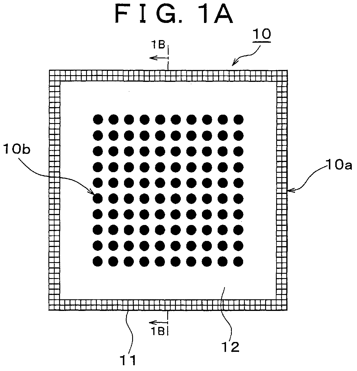
- Figs. 1A, 1B show a separator of the fuel cell according to an embodiment of the invention.
- the separator 10 is constituted by a substrate 10a and a plurality of protrusions 10b.
- the substrate 10a is constituting a mesh foundation 11 and resin layers 12 made of synthetic resin which are bonded to both front and rear surfaces of the mesh foundation 11 in order to cover both front and rear surfaces.
- Figs. 2A, 2B show the mesh foundation 11 which constitutes the substrate 10a.
- Figs. 3A, 3B show the substrate 10a in which both front and rear surfaces of the mesh foundation 11 are covered with the resin layers 12.
- Fig. 4 shows schematically an arrangement of the separator in the fuel cell.
- each protrusion 10b is composed of black lead compound of black lead paint and formed by being dried and solidified (harden) in such a condition that it is implanted in the substrate 10a.
- the mesh foundation 11 has a predetermined rough mesh size, which is set up to a size allowing the black lead compound of black lead paint for composing the protrusion 10b to pass through.
- the mesh foundation 11 is formed by weaving synthetic fibers such as inorganic fibers including glass fiber, carbon fiber, metallic fiber and the like, polyester fiber and polyamide fiber and the like.
- Nonconductive synthetic resin such as polyvinylidene chloride and polyacrylonitrile is applied on the mesh foundation 11 and then, both front and rear surfaces are covered with the resin layers 12 made of synthetic resin so as to produce the substrate 10a.
- Figs. 3A, 3B show the substrate 10a.
- the resin layer 12 constituting the substrate 10a has the function for shielding fuel gas and reactive gas in the fuel cell and includes a plurality of through holes 12a which pass through between the front surface and the rear surface.
- Each through hole 12a is open to the mesh foundation 11. Therefore, each through hole 12a passes through mesh holes in the mesh foundation between the front surface and the rear surface.
- the through hole may be formed of a through hole in the mesh foundation and a mesh hole in the mesh foundation and it is permissible to construct the resin layer integrally with the mesh foundation.
- Black lead coated on the resin layer 12 of the substrate 10a invades each through hole 12a in the substrate 10a so that it is implanted therein.
- the black lead paint implanted forms each protrusion 10b after being dried and solidified (harden).
- positive and negative electrodes 21a, 21b are disposed between solid electrolyte films 22 bonded on the right and left faces so as to form a fuel cell.
- an end of each protrusion 10b makes contact with one electrode 21a while the other end makes contact with the other electrode 21b.
- the substrate 10a shields a gap between both solid electrolyte films 22 so as to form reaction chambers 23a, 23b in which fuel gas (hydrogen gas) or oxidant gas (air) is introduced.
- the separator 10 is produced according to a manufacturing process shown in a flow chart of Fig. 5.
- This manufacturing process indicates an example of the manufacturing method of the separator according to the invention, and includes a substrate manufacturing step (S1) for producing the substrate 10a (see Figs. 6A, 6B, 7A, 7B), a black lead paint coating step (S2) (see Figs. 8A, 8B, 9A and 9B) for implanting each protrusion 10b in the substrate 10a, a drying/solidifying step (a hardening step) (S3) for drying and solidifying (hardening) each protrusion 10b and a grinding step (S4) for grinding each dried and solidified protrusion 10b and a cut step (S5) for cutting the separator in a predetermined size.
- the first method is using a substrate creating plate 30a shown in substrate creating process diagram shown in Figs. 6A, 6B.
- the substrate creating plate 30a is prepared by stretching a screen 32 on the peripheral portion of an opening in a frame body 31.
- the screen 32 is formed by weaving inorganic fiber such as stainless fiber or synthetic fiber such as polyamide fiber, polyester fiber.
- the screen 32 is coated with diazo photo-sensitive emulsion and then processed according to photographic sensitive method so that it has a plurality of through holes 32a in its surface.
- the screen 32 of the substrate creating plate 30a may be produced by drilling appropriately a metallic plate such as stainless plate or synthetic resin plate to form a plurality of through holes.
- a drilling means machine processing, punching, electric discharge processing, laser processing, water jet processing, etching, sand blasting and the like may be applied.
- the screen 32 is coated with synthetic reisn 12b (screen printing) to form the resin layer 12. Consequently, the synthetic resin 12b is applied to the surface of the mesh foundation 11 through each through hole 32a and conveyed through to the rear surface of the mesh foundation 11 so as to form the resin layer 12 on both front and rear surfaces of the mesh foundation 11. In this case, coating with synthetic resin 12b is carried out with a doctor knife 33. Other portions than the through holes in the screen 32 exert masking function to synthetic resin so as to form the through holes 12a at corresponding positions of the mesh foundation 11. Consequently, the substrate 10a is created as shown in Fig. 6B.
- the screen placed on the mesh foundation 11 is coated with synthetic resin 12b for forming the resin layer 12 (screen printing) so as to form the resin layer 12c on both front and rear surfaces of the mesh foundation 11. Then, this is placed on a lower sheet 34 and irradiated with strong light from above. Consequently, a portion in the resin layer 12c corresponding to a black portion 34a on the lower sheet 34 is melted so as to form a through hole 12a and finally, the substrate 10a shown in Fig. 7B is created. A film may be pasted on both front and rear surfaces of the mesh foundation 11 instead of the resin layer 12c.
- the mesh foundation 11 is placed on the lower sheet 34 and irradiated with strong light so that a portion in the film corresponding to the block portion of the lower sheet is melted to form the through holes.
- black lead ink black lead paint
- black lead paint which is a carbon base conductive paint for black lead printing, prepared preliminarily is used.
- the black lead paint is prepared in ink-like condition and applied onto the substrate according to a printing method for forming each protrusion on the substrate.
- black lead such as natural black lead, artificial black lead, thermally expanded black lead or carbon black such as acetylene black, Ketjen black, denka black, furnace black is employed and an appropriate resin binder is added thereto and mixed together.
- a solvent is added as required to adjust the viscosity to one suitable to printing.
- black lead ink a type in which black lead powder or carbon black powder (hereinafter referred to generally as carbon powder) is mixed with acrylic resin binder and the viscosity is adjusted with an appropriate solvent
- carbon powder a type in which carbon powder and epoxy resin binder are mixed together and the viscosity is adjusted with an appropriate solvent
- carbon powder and phenol resin binder are mixed together and the viscosity is adjusted with an appropriate solvent
- carbon powder and various types of thermoplastic resin binders are mixed together and the viscosity is adjusted with an appropriate solvent and others can be mentioned.
- thermoplastic type thermosetting type
- UV hardening type EB hardening type
- thermosetting binder is employed as the resin binder for each of these black lead inks
- the binder needs to be subjected to hardening processing after printing with black lead ink.
- thermoplastic binder is employed as the resin binder, the carbon powder and the resin binder are heated to a melting temperature and agitated together so as to regulate the black lead ink having an appropriate viscosity.
- the black lead printing plate 30b functions as a mask when the black lead ink is printed on the substrate 10a and composed in the same way as the substrate creating plate 30a.
- a plurality of through holes 35a are formed in the screen 35 stretched on the peripheral portion of an opening portion on an end of the frame 34 such that they oppose the through holes 12a possessed by the resin layer 12 of the substrate 10a.
- two types of printing bases 30a, 30d shown in Figs. 8A, 8C are employed.
- the first printing base 30c has a flat smooth top face and the second printing base 30d has a plurality of recess portions 36 opposing the through holes 35a in the black lead printing plate 30b.
- the substrate 10a Upon printing the black lead ink 13 on the substrate 10a, the substrate 10a is placed on the first printing base 30c as shown in Fig. 8A and the black lead printing plate 30b is placed on the substrate 10a. Then, the black lead ink 13 supplied onto the screen 35 of the black lead printing plate 30b is printed using the doctor knife 37. By this printing, the black lead ink 13 invades the respective through holes 35a in the screen 35 and reaches a top face of the first printing base 30c through the through hole 12a in the resin layer 12 of the substrate 10a. Consequently, as shown in Fig. 8B, a plurality of half protrusions 13a protruded from one side are formed on the substrate 10a. Each half protrusion 13a has a length corresponding to the depth of the through hole 35a in the screen 35 of the black lead printing plate 30b.
- the substrate 10a implanted with the respective half protrusions 13a is inverted and placed on the second printing base 30d, and the black lead printing plate 30b is placed on the thus inverted substrate 10a. Then, the black lead ink 13 supplied to the screen 35 of the black lead printing plate 30b is printed using the doctor knife 37.
- the respective half protrusions 13a are fit to the respective recess portions 36 in the second printing base 30d.
- the black lead ink 13 invades the respective through holes 35a in the screen 35 and reaches an end portion of the half protrusion 13a located in the through hole 12a in the resin layer 12 of the substrate 10a, so as to form the half protrusion 13b adjoining the end portion of the half protrusion 13a. Consequently, both half protrusions 13a, 13b are joined together so as to form the protrusion 10b.
- the half protrusion 13b has a length corresponding to the depth of the through hole 35a in the screen 35 of the black lead printing plate 30b. As shown in Fig. 8D, each protrusion 10b protrudes from both front and rear surfaces such that it penetrates the through hole 12a in the resin layer 12.
- Figs. 9A, 9B show a method for forming the protrusion 10b on the substrate 10a by a single printing action.
- the black lead printing plate 30b and the second printing base 30d are employed.
- the substrate 10a is placed on the second printing base 30d and the black lead printing plate 30b is placed on the substrate 10a, such that the respective through holes 35a in the black lead printing plate 30b, the respective through holes 12a in the substrate 10a and the respective recess portions 36 in the second printing base 30d oppose each other.
- the black lead ink 13 is supplied to the screen 35 of the black lead printing plate 30b in this condition and the thus supplied black lead ink 13 is printed with the doctor knife 37.
- the black lead ink 13 reaches the respective through holes 35a in the black lead printing plate 30b, the respective through holes 12a in the substrate 10a and the respective recess portions 36 in the second printing base 30d so as to form the respective protrusions 10b as shown in Fig. 9B.
- the separator 10 in which a plurality of the protrusions 10b are implanted in the substrate 10a is created. After that, this separator 10 is subjected to hardening process, in which the respective protrusions 10b are hardened.
- this separator 10 is subjected to hardening process, in which the respective protrusions 10b are hardened.
- the hardening process it is possible to employ drying/solidifying means, cooling/solidification means or other hardening means depending on the type of resin binder to be used.
- the separator 10 is subjected to grinding process as required and then the cutting process.
- the grinding process the surfaces of the formed protrusions 10b in contact with the electrodes 21a, 21b are ground. Consequently, resin binder adhering to a portion contacting the electrodes 21a, 21b of each protrusion 10b is removed so as to secure an excellent conductivity of each protrusion 10b.
- the separator 10 created in a large area is cut into a size suitable for a fuel cell for use.
- the substrate 10a has a multiple layered structure in which both surfaces of the mesh foundation 11 are covered with the resin layers 12, so that the thickness of the substrate 10a is very small.
- the separator 10 can be constructed in which the thickness of the substrate 10a that becomes a dead space within the structure of a fuel cell is very small.
- the fuel cell can be formed in a small size in the direction of laminating respective components and the weight of the fuel cell can be greatly reduced.
- the black lead ink 13 which is a black lead paint, is applied to a single side or both sides of the substrate 10a so that it invades the through holes 12a in the substrate 10a. Then, the respective protrusions 10b are formed of black lead component of the black lead ink 13. Therefore, the respective protrusions 10b can be formed on the substrate 10a in a very short time, thereby making it possible to greatly reduce manufacturing time and cost for the separator 10.
- the respective protrusions 10b are formed according to the method of coating the substrate 10a with the black lead ink 13, cost on a manufacturing die of the separator 10 can be greatly reduced. From this point of view also, the manufacturing cost of the separator 10 can be greatly reduced and at the same time, it is possible to correspond to diversification of the types of the separators easily.
- the separator for the fuel cell is employed.
- the embodiments do not limit the separator.
- a conductive plate may be manufactured by the method described in the embodiment.
Landscapes
- Chemical & Material Sciences (AREA)
- Life Sciences & Earth Sciences (AREA)
- Engineering & Computer Science (AREA)
- Manufacturing & Machinery (AREA)
- Sustainable Development (AREA)
- Sustainable Energy (AREA)
- Chemical Kinetics & Catalysis (AREA)
- Electrochemistry (AREA)
- General Chemical & Material Sciences (AREA)
- Composite Materials (AREA)
- Fuel Cell (AREA)
Abstract
Description
Claims (13)
- A conductive plate comprising a substrate (10a) and a plurality of protrusions (10b) implanted in the substrate (10a) such that they protrude from a single side or both sides of the substrate (10a), characterized in that;
said substrate (10a) has a multiple layered structure in which a single side or both sides of the mesh foundation are covered with resin layer (12) and contains through holes (12a) at positions corresponding to each of the protrusions (10b) and that the protrusions are formed by invasion of the black lead paint (13) applied on the single side or both sides of the substrate (10a) into each of the through holes (12a) in the substrate (10a). - A conductive plate as claimed in claim 1, characterized in that;
the mesh foundation (11) composing said substrate (10a) is a foundation having mesh holes through which said black lead paint is capable of passing, and
said resin layer (12) has through holes at positions corresponding to each of said protrusions (10b). - A conductive plate as claimed in claim 1 or 2, characterized in that;
said black lead paint is a black lead ink adjusted to a low viscosity by mixing black lead powder with resin made binder while said black lead ink is printed on a single side or both sides of said substrate (10a) so that it invades the through holes (12a) in said substrate (10a) so as to form each of said protrusions (10b). - A conductive plate as claimed in any one of claims 1 to 3
characterized in that;
said conductive plate is a separator for a fuel cell, said protrusions being in contact with electrodes of said fuel cell. - A manufacturing method for a conductive plate characterized by comprising:a step (S1) of preparing a mesh foundation (11);a step (S1) of forming a substrate by covering said mesh foundation (11) with a resin layer, said resin layer (12) being formed by coating a single side or both sides of said mesh foundation (11) with resin or impregnating the mesh foundation (11) with resin and having the through holes (12a) at predetermined positions and;a step (S2) of forming protrusions (10b) protruding from a single side or both sides of the substrate (10a) at positions corresponding to the through holes (12a) in said resin layer (12) by coating the single side or both sides of said substrate (10a) with said black lead paint; anda step (S3) of hardening said protrusions (10b) formed on said substrate (10a).
- A manufacturing method according to claim 5, characterized by further comprising:after said hardening step (S3), grinding the surface of each of said protrusions (10b) which makes contact with said electrodes.
- A manufacturing method according to claim 5 or 6, characterized in that;
in said substrate forming step (S1), placing a screen (32) on said mesh foundation (11), said screen (12) having through holes (32a) facing positions of said mesh foundation (11) to be covered with resin, and
coating said resin (12b) on said screen (12), said resin (12b) being coated on said mesh foundation (11) through said through holes (32a) of said screen (12) so as to form said substrate (10a) in which said mesh foundation (11) are covered with said rein layer (12) having said through holes (12a) at said predetermined positions. - A manufacturing method according to claim 5 or 6, characterized in that;
in said substrate forming step (S1), placing said mesh foundation (11) in which said both sides of said mesh foundation (11) are covered with said resin layer (12c) on a base (34) having black portions (34a) facing positions of said substrate (10a) in which said through holes (12a) are to be formed,
irradiating said mesh foundation (11) with light so as to melt said resin layer (12c) corresponding to said black portions (34a), said through holes (12a) being formed at said predetermined positions in said substrate (10a). - A manufacturing method according to any one of claims 5 to 8, characterized in that;
said substrate (10a) having a first surface and a second surface facing in a direction opposite to said first surface,
in said protrusions forming step (S2), placing said substrate (10a) on a first base (30c) so that said first surface faces upward,placing said screen (35) on said first surface of said substrate (10a), said screen (35) having through holes (35a) facing positions of said mesh foundation (11) on which said protrusions (13a) are to be informed,covering said black leas paint (13) on said screen (35) to invade through holes (12a) of said substrate (10a) through said through holes (35a) of said screen (35) so as to form said protrusions (13a) which are protruded on said first surface integrally with said substrate (10a),placing said substrate (10a) in which said protrusions (13a) are protruded on said first surface, on a second base (30d) so that said second surface faces upward,placing said screen (35) on said second surface of said substrate (10a), said screen (35) having through holes (35a) facing positions of said mesh foundation (11) on which said protrusions (13b) are to be formed,coverning said black leas paint (13) on said screen (35) to reach and adjoin an end portion of said protrusions (13a) located in said through holes (12a) of said substrate (10a) through said through holes (35a) of said screen (35), so as to form protrusions (13b) which are protruded on said second surface integrally with said substrate (10a). - A manufacturing method according to any one of claims 5 to 8 characterized in that;
in said protrusions forming step (S2), placing said substrate (10a) on a base (30d) having holes (36), said holes (36) being located to face positions to be formed said protrusions (10b),placing said screen (35) having through holes (35a), said through holes (35a) being located facing positions in which said protrusions (13b) are to be formed, andcovering said black leas paint (13) on said screen (35) to invade through holes (12a) of said substrate (10a) through said through holes (35a) of said screen (35) to reach a bottom of said holes (36) of said base (30d) so as to form protrusions (10b) which are protruded on said first surface and second surface integrally with said substrate (10a). - A manufacturing method according to claim 5 characterized in that;
said conductive plate is a separator for a fuel cell, said separator forming a reactive chamber of said fuel cell, said protrusions being in contact with electrodes of said fuel cell. - A conductive plate obtainable by the manufacturing method according to claim 5.
- A conductive plate obtainable by the manufacturing method according to claim 6.
Applications Claiming Priority (2)
| Application Number | Priority Date | Filing Date | Title |
|---|---|---|---|
| JP2000361330A JP2002164062A (en) | 2000-11-28 | 2000-11-28 | Separator for fuel cell and its method of manufacture |
| JP2000361330 | 2000-11-28 |
Publications (2)
| Publication Number | Publication Date |
|---|---|
| EP1211742A2 true EP1211742A2 (en) | 2002-06-05 |
| EP1211742A3 EP1211742A3 (en) | 2006-07-19 |
Family
ID=18832781
Family Applications (1)
| Application Number | Title | Priority Date | Filing Date |
|---|---|---|---|
| EP01128192A Withdrawn EP1211742A3 (en) | 2000-11-28 | 2001-11-27 | Conductive plate and manufacturing method thereof |
Country Status (3)
| Country | Link |
|---|---|
| US (1) | US6645658B2 (en) |
| EP (1) | EP1211742A3 (en) |
| JP (1) | JP2002164062A (en) |
Cited By (3)
| Publication number | Priority date | Publication date | Assignee | Title |
|---|---|---|---|---|
| WO2007061407A3 (en) * | 2004-12-29 | 2007-10-04 | 3M Innovative Properties Co | Z-axis electrically conducting flow field separator |
| WO2010039434A3 (en) * | 2008-09-30 | 2010-05-27 | Battelle Memorial Institute | Cassettes for solid-oxide fuel cell stacks and methods of making the same |
| WO2014000997A1 (en) * | 2012-06-29 | 2014-01-03 | Siemens Aktiengesellschaft | Electrical energy store |
Families Citing this family (26)
| Publication number | Priority date | Publication date | Assignee | Title |
|---|---|---|---|---|
| US20020022170A1 (en) * | 2000-08-18 | 2002-02-21 | Franklin Jerrold E. | Integrated and modular BSP/MEA/manifold plates for fuel cells |
| FR2832549B1 (en) * | 2001-11-16 | 2004-05-28 | Commissariat Energie Atomique | FUEL CELL WITH SIGNIFICANT ACTIVE SURFACE AND REDUCED VOLUME AND METHOD FOR MANUFACTURING THE SAME |
| US7125625B2 (en) * | 2002-05-31 | 2006-10-24 | Lynnetech, Inc. | Electrochemical cell and bipolar assembly for an electrochemical cell |
| US20040053104A1 (en) * | 2002-09-12 | 2004-03-18 | Novkov Donald James | Current feeders for electrochemical cell stacks |
| TWI241732B (en) * | 2002-09-25 | 2005-10-11 | E I Du Pont Canada Company | Mesh reinforced fuel cell separator plate |
| JP2005044789A (en) * | 2003-07-04 | 2005-02-17 | Nisshinbo Ind Inc | Porous fuel cell separator, method for producing porous fuel cell separator, and polymer electrolyte fuel cell |
| US7670707B2 (en) * | 2003-07-30 | 2010-03-02 | Altergy Systems, Inc. | Electrical contacts for fuel cells |
| US8679674B2 (en) | 2005-03-25 | 2014-03-25 | Front Edge Technology, Inc. | Battery with protective packaging |
| US7846579B2 (en) | 2005-03-25 | 2010-12-07 | Victor Krasnov | Thin film battery with protective packaging |
| US7862927B2 (en) | 2007-03-02 | 2011-01-04 | Front Edge Technology | Thin film battery and manufacturing method |
| US8870974B2 (en) | 2008-02-18 | 2014-10-28 | Front Edge Technology, Inc. | Thin film battery fabrication using laser shaping |
| US7862627B2 (en) | 2007-04-27 | 2011-01-04 | Front Edge Technology, Inc. | Thin film battery substrate cutting and fabrication process |
| US8628645B2 (en) | 2007-09-04 | 2014-01-14 | Front Edge Technology, Inc. | Manufacturing method for thin film battery |
| US8502494B2 (en) | 2009-08-28 | 2013-08-06 | Front Edge Technology, Inc. | Battery charging apparatus and method |
| US8865340B2 (en) | 2011-10-20 | 2014-10-21 | Front Edge Technology Inc. | Thin film battery packaging formed by localized heating |
| US9887429B2 (en) | 2011-12-21 | 2018-02-06 | Front Edge Technology Inc. | Laminated lithium battery |
| US8864954B2 (en) | 2011-12-23 | 2014-10-21 | Front Edge Technology Inc. | Sputtering lithium-containing material with multiple targets |
| US9257695B2 (en) | 2012-03-29 | 2016-02-09 | Front Edge Technology, Inc. | Localized heat treatment of battery component films |
| US9077000B2 (en) | 2012-03-29 | 2015-07-07 | Front Edge Technology, Inc. | Thin film battery and localized heat treatment |
| US9159964B2 (en) | 2012-09-25 | 2015-10-13 | Front Edge Technology, Inc. | Solid state battery having mismatched battery cells |
| US8753724B2 (en) | 2012-09-26 | 2014-06-17 | Front Edge Technology Inc. | Plasma deposition on a partially formed battery through a mesh screen |
| US9356320B2 (en) | 2012-10-15 | 2016-05-31 | Front Edge Technology Inc. | Lithium battery having low leakage anode |
| KR101454081B1 (en) | 2012-12-26 | 2014-10-22 | 삼성전기주식회사 | Solid oxide fuel cell |
| US10008739B2 (en) | 2015-02-23 | 2018-06-26 | Front Edge Technology, Inc. | Solid-state lithium battery with electrolyte |
| US10957886B2 (en) | 2018-03-14 | 2021-03-23 | Front Edge Technology, Inc. | Battery having multilayer protective casing |
| FR3115217B1 (en) * | 2020-10-16 | 2023-12-08 | Novares France | Water separator intended to be integrated into a hydrogen engine of a vehicle |
Family Cites Families (9)
| Publication number | Priority date | Publication date | Assignee | Title |
|---|---|---|---|---|
| US4658499A (en) * | 1982-02-08 | 1987-04-21 | California Institute Of Technology | Bipolar battery plate |
| JPS59149657A (en) * | 1983-02-02 | 1984-08-27 | Toshiba Corp | Fuel cell |
| JPH0574469A (en) | 1991-09-12 | 1993-03-26 | Yamaha Motor Co Ltd | Fuel cell separator |
| DE4443688C1 (en) * | 1994-12-08 | 1996-03-28 | Mtu Friedrichshafen Gmbh | Bipolar plate for fuel-cell stack anode and cathode sepn. and contact |
| KR100372926B1 (en) * | 1998-06-02 | 2003-02-25 | 마쯔시다덴기산교 가부시키가이샤 | Polymer electrolyte fuel cell and method of manufacture thereof |
| CA2303212A1 (en) * | 1998-07-10 | 2000-01-20 | Kabushiki Kaisha Toyota Chuo Kenkyusho | A fuel cell separator and a method for producing the same |
| JP2000133282A (en) * | 1998-10-21 | 2000-05-12 | Ishikawajima Harima Heavy Ind Co Ltd | Solid polymer electrolyte fuel cell separator |
| ID26558A (en) | 1998-12-25 | 2001-01-18 | Araco Kk | FUEL BATTERY, SEPARATOR FOR FUEL BATTERY AND SEPARATOR MAKING METHOD |
| US6146779A (en) * | 1999-04-01 | 2000-11-14 | Plug Power Inc. | Fluid flow plate, fuel cell assembly system, and method employing same for controlling heat in fuel cells |
-
2000
- 2000-11-28 JP JP2000361330A patent/JP2002164062A/en active Pending
-
2001
- 2001-11-26 US US09/991,996 patent/US6645658B2/en not_active Expired - Fee Related
- 2001-11-27 EP EP01128192A patent/EP1211742A3/en not_active Withdrawn
Cited By (7)
| Publication number | Priority date | Publication date | Assignee | Title |
|---|---|---|---|---|
| WO2007061407A3 (en) * | 2004-12-29 | 2007-10-04 | 3M Innovative Properties Co | Z-axis electrically conducting flow field separator |
| US7862956B2 (en) | 2004-12-29 | 2011-01-04 | 3M Innovative Properties Company | Z-axis electrically conducting flow field separator |
| WO2010039434A3 (en) * | 2008-09-30 | 2010-05-27 | Battelle Memorial Institute | Cassettes for solid-oxide fuel cell stacks and methods of making the same |
| US8293426B2 (en) | 2008-09-30 | 2012-10-23 | Battelle Memorial Institute | Cassettes for solid-oxide fuel cell stacks and methods of making the same |
| AU2009298953B2 (en) * | 2008-09-30 | 2016-07-07 | Battelle Memorial Institute | Cassettes for solid-oxide fuel cell stacks and methods of making the same |
| WO2014000997A1 (en) * | 2012-06-29 | 2014-01-03 | Siemens Aktiengesellschaft | Electrical energy store |
| US10096874B2 (en) | 2012-06-29 | 2018-10-09 | Siemens Aktiengesellschaft | Electrical energy store |
Also Published As
| Publication number | Publication date |
|---|---|
| EP1211742A3 (en) | 2006-07-19 |
| JP2002164062A (en) | 2002-06-07 |
| US20020065000A1 (en) | 2002-05-30 |
| US6645658B2 (en) | 2003-11-11 |
Similar Documents
| Publication | Publication Date | Title |
|---|---|---|
| US6645658B2 (en) | Conductive plate and manufacturing method thereof | |
| Christensen et al. | Cyclable lithium and capacity loss in Li-ion cells | |
| AU2003239177B2 (en) | Carbon fiber reinforced plastic bipolar plates with continuous electrical pathways | |
| EP0570590A1 (en) | Thin battery and monolithic thin battery | |
| US5431701A (en) | Manufacturing method of film type battery | |
| EP2359429A1 (en) | Multifunctional composite | |
| CN108352532A (en) | It is capable of basic material and layer compound, its manufacturing method and its application of conduction | |
| KR20140031148A (en) | Method for fabricating a fuel cell including a membrane-electrode assembly | |
| KR20170094983A (en) | An electrode for an electrochemical device and a method for manufacturing the same | |
| EP0560731A1 (en) | Laminated fuel cell components | |
| US6740442B1 (en) | Unit cell of flat solid oxide fuel cell and fuel cell stack comprising the same | |
| EP1796195B1 (en) | Method of producing gasket for fuel cells | |
| US6224993B1 (en) | Electrolyte for solid oxide fuel cells | |
| EP3552235A1 (en) | Parallelisable method for integrating power chips and power electronics modules | |
| CN114824496B (en) | Laminated electrode body, resin-fixed laminated electrode body, and all-solid-state battery | |
| CN102106028B (en) | Membrane-electrode assembly, method of producing the assembly, and solid polymer-type fuel cell employing the same | |
| KR102295101B1 (en) | Manufacturing method of secondary battery comprising electrode with 3 dimensional structure using electrode stacking technique | |
| JPH0434871A (en) | Manufacture of battery | |
| KR102352369B1 (en) | Preparation method of parts for redox flow battery and redox flow battery including the same | |
| US20080116609A1 (en) | In-Situ Molding Of Fuel Cell Separator Plate Reinforcement | |
| EP4588118A1 (en) | Ceramic composite separator and method for manufacturing the same | |
| JP2004335121A (en) | Fuel cell and manufacturing method thereof | |
| KR20160133265A (en) | Composite separation plate for fuel cell and method for manufacturing the same | |
| US20240113393A1 (en) | Protective coatings for lithium metal anodes including edges | |
| Das et al. | Materials and Applications of 3D Print for Solid-State Batteries |
Legal Events
| Date | Code | Title | Description |
|---|---|---|---|
| PUAI | Public reference made under article 153(3) epc to a published international application that has entered the european phase |
Free format text: ORIGINAL CODE: 0009012 |
|
| 17P | Request for examination filed |
Effective date: 20011224 |
|
| AK | Designated contracting states |
Kind code of ref document: A2 Designated state(s): AT BE CH CY DE DK ES FI FR GB GR IE IT LI LU MC NL PT SE TR |
|
| AX | Request for extension of the european patent |
Free format text: AL;LT;LV;MK;RO;SI |
|
| RAP1 | Party data changed (applicant data changed or rights of an application transferred) |
Owner name: ARACO KABUSHIKI KAISHA |
|
| PUAL | Search report despatched |
Free format text: ORIGINAL CODE: 0009013 |
|
| AK | Designated contracting states |
Kind code of ref document: A3 Designated state(s): AT BE CH CY DE DK ES FI FR GB GR IE IT LI LU MC NL PT SE TR |
|
| AX | Request for extension of the european patent |
Extension state: AL LT LV MK RO SI |
|
| RIC1 | Information provided on ipc code assigned before grant |
Ipc: H01M 8/10 20060101ALI20060609BHEP Ipc: H01M 8/02 20060101AFI20020416BHEP |
|
| AKX | Designation fees paid |
Designated state(s): DE FR GB |
|
| 17Q | First examination report despatched |
Effective date: 20070905 |
|
| STAA | Information on the status of an ep patent application or granted ep patent |
Free format text: STATUS: THE APPLICATION IS DEEMED TO BE WITHDRAWN |
|
| 18D | Application deemed to be withdrawn |
Effective date: 20080116 |