EP1211636A1 - Filtering device and method for reducing noise in electrical signals, in particular acoustic signals and images - Google Patents
Filtering device and method for reducing noise in electrical signals, in particular acoustic signals and images Download PDFInfo
- Publication number
- EP1211636A1 EP1211636A1 EP00830782A EP00830782A EP1211636A1 EP 1211636 A1 EP1211636 A1 EP 1211636A1 EP 00830782 A EP00830782 A EP 00830782A EP 00830782 A EP00830782 A EP 00830782A EP 1211636 A1 EP1211636 A1 EP 1211636A1
- Authority
- EP
- European Patent Office
- Prior art keywords
- samples
- signal
- input
- sample
- fuzzy
- Prior art date
- Legal status (The legal status is an assumption and is not a legal conclusion. Google has not performed a legal analysis and makes no representation as to the accuracy of the status listed.)
- Withdrawn
Links
Images


Classifications
-
- G—PHYSICS
- G06—COMPUTING; CALCULATING OR COUNTING
- G06N—COMPUTING ARRANGEMENTS BASED ON SPECIFIC COMPUTATIONAL MODELS
- G06N3/00—Computing arrangements based on biological models
- G06N3/02—Neural networks
- G06N3/04—Architecture, e.g. interconnection topology
- G06N3/043—Architecture, e.g. interconnection topology based on fuzzy logic, fuzzy membership or fuzzy inference, e.g. adaptive neuro-fuzzy inference systems [ANFIS]
-
- G—PHYSICS
- G06—COMPUTING; CALCULATING OR COUNTING
- G06F—ELECTRIC DIGITAL DATA PROCESSING
- G06F2218/00—Aspects of pattern recognition specially adapted for signal processing
- G06F2218/02—Preprocessing
- G06F2218/04—Denoising
Definitions
- the present invention refers to a filtering device and method for reducing noise in electrical signals, in particular acoustic (voice) signals and images.
- undesired components may be any type of noise (white noise, flicker, etc.) or other types of superimposed acoustic or visual signals.
- Linear filters are at present the most widely used instruments for filtering noise.
- Finite-impulse filters FIRs eliminate all the harmonics of a signal having a frequency higher than the cutoff frequency of the filter and improve the signal-to-noise ratio (SNR).
- FFT fast Fourier transform
- Another linear filtering technique is based on the fast Fourier transform (FFT), where the signal is transformed into the frequency domain, the undesired harmonics are removed, and then the inverse Fourier transform is calculated.
- average filters are simple to design and may be implemented through simple hardware circuits. Average filters are based on the comparison of the individual signal samples in an time interval with the average of all the samples in the same time interval. On the basis of this comparison, the individual samples are selectively attenuated.
- the aim of the invention is thus to provide a filtering method and device that does not cause a sensible deterioration of the signal and at the same time preserves the edges of the signal.
- a device and method are provided for filtering electrical signals, as respectively defined in Claim 1 and Claim 24.
- the filter and the method described are particularly useful in the case of signals having steep edges, for which the aim is to preserve the edges of the signals. Furthermore, it is possible to filter signals affected by white and non-white noise, such as flicker noise. Through the present method it is moreover possible to eliminate from a signal other signals that are superimposed on it and are characterized by a wide spectral range.
- the device and the method described are based upon a neuro-fuzzy network. They are implemented with a moving-average filtering technique in which the weighting factors (or weights) for the final reconstruction of the signal are calculated in a neuro-fuzzy network according to specific fuzzy rules. This enables a better reduction of the noise.
- the fuzzy rules operate on different variables, referred to as signal features. Described hereinafter are three signal features and six fuzzy rules.
- the proposed filter is suitable for visual signals or acoustic signals, even ones with sudden variations.
- Various types of functions or signal features can be used to create the rules. With the method described, the signal features are correlated to the position of the sample in the considered sample window, to the difference between a given sample and the sample at the center of the window, and to the difference between a given sample and the average of samples in the window. These signal features may have a considerable influence on the values of the weights for the reconstruction of the signal; in addition, they may be calculated in a relatively simple manner.
- the method and the filter according to the invention moreover comprise a neuro-fuzzy filter bank.
- the signal may be split into different sub-bands according to wavelet theory: each sub-band signal may be filtered by a neuro-fuzzy network, and then the various sub-bands can be reconstructed by the synthesis filter bank.
- wavelet theory in the first sub-band the signal features have a low frequency, whereas in the last sub-band the signal features have the maximum frequency. If non-white noise (colored noise) is to be removed, this is approximated by white noise in each individual sub-band. Given that a neuro-fuzzy network works well on white noise, this solution leads to a sensible reduction in noise.
- the network is trained by supplying some configurations of input and output signals (the configuration of the output signal that it is required to obtain as a result of the network evolution is called target configuration).
- the training algorithm is based upon one of the known learning methods, such as gradient descent, a genetic algorithm, the simulated annealing method, random search, or any other method for function optimization.
- Figure 1 shows a filter 1 comprising a signal-feature computation unit 2, a neuro-fuzzy network 3, a reconstruction unit 4, and a training unit 5.
- the signal-feature computation unit 2 receives at the input a signal In including of a plurality of input samples e ( i ), stores, at each clock cycle, (2 N + 1) input samples e ( i ) (which represent a work window for filter 1) in an internal buffer, computes the signal features X 1( i ), X 2( i ), and X 3( i ) for each input sample e ( i ) on the basis of all the input samples belonging to the work window (as described in detail hereinafter), and supplies the signal features X 1( i ), X 2( i ), and X 3( i ) thus calculated to the neuro-fuzzy network 3.
- the neuro-fuzzy network 3 processes the signal features X 1( i ), X 2( i ), and X 3( i ) and generates at the output a reconstruction weight oL 3( i ) for each input sample e ( i ).
- the neuro-fuzzy network 3 first performs a fuzzification operation, then applies preset fuzzy rules, and finally carries out a defuzzification operation.
- the reconstruction weight oL 3( i ) thus obtained is hence the weighted sum of all the input samples e ( i ) in the same work window, as explained in detail hereinafter with reference to Figures 2 and 3.
- the reconstruction unit 4 receives the reconstruction weights oL 3( i ) and the input samples e ( i ) and, after accumulating a sufficient number of input samples e ( i ) and of corresponding reconstruction weights oL 3( i ), generates an output sample u ( i ) the sequence of which forms an output signal Out.
- the training unit 5 is operative only initially, so as to train the neuro-fuzzy network 3 and modify the weights of the network with the aim of obtaining an optimal behavior of the filter 1, as described in detail hereinafter.
- the signal features X 1( i ), X 2( i ), and X 3( i ), computed in the signal-feature computation unit 2 are correlated, respectively, to the distance between each sample and the central sample of the considered window, to the difference between a given sample and the sample at the center of the window, and to the difference between a given sample and the average of samples in the window, and are normalized so as to obtain values between 0 and 1.
- the neuro-fuzzy network 3 is a three-layer fuzzy network the functional representation of which appears in Figure 2, in which, for reasons of simplicity, the index i in parenthesis for the specific sample within the respective work window is not indicated. Nevertheless, as mentioned above, and as will emerge more clearly from the flowchart of Figures 3a, 3b, the neuro-fuzzy processing represented by Figure 2 is repeated for each input sample e ( i ).
- first-layer neurons 6 each of which, starting from the three signal features X 1, X 2 and X 3 (generically designated by X1 ) and using as weights the average value W m ( l, k ) and the variance W v ( l, k ) of the membership functions, supplies a first-layer output oL 1( l , k ) (hereinafter also designated by oL 1( m )) calculated as follows:
- a fuzzy AND operation is performed, using the norm of the minimum, in such a way as to obtain N second-layer outputs oL 2 ( n ).
- N is equal to 6.
- a fuzzy AND operation using the norm of the minimum is based upon rules of the type:
- each second-layer output oL 2( n ) is equal to the minimum one among the products of the M outputs oL 1( m ) of the first-layer neurons 6 and a respective second-layer weight W FA ( m , n ).
- the third layer corresponds to a defuzzification operation and supplies at output a discrete-type reconstruction weight oL 3, using N third-layer weights W DF ( n ).
- the defuzzification method is that of the center of gravity (centroid) and is represented in Figure 2 by a third-layer neuron 8 supplying the reconstruction weight oL 3 according to the equation
- the training unit 5 operates only in an initial learning stage, when an input signal In having a known configuration is supplied to the filter 1, the output signal Out obtained is compared with a target signal Tg, and the distance between the obtained signal Out and the target signal Tg is evaluated on the basis of a fitness function.
- This fitness function may be, for example, the quadratic signal/noise ratio having the following expression: in which T is the total number of input samples e ( i ).
- the first-layer weights (mean value W m ( l , k ) and variance W v ( l , k ) of the gaussian membership functions) and the third-layer weights W DF ( n ) are modified, and a new fitness evaluation is performed.
- the second-layer weights W FA ( m , n ) are instead randomly initialized and are not modified.
- the learning process is iterated until a preset value of the fitness function is achieved or until a preset number of genetic algorithms have been generated or a preset number of steps of the selected optimization algorithm has been performed.
- the neuro-fuzzy network 3 implements an adaptive algorithm and overcomes the limitations of neural networks or of fuzzy systems considered separately.
- fuzzy systems do not have learning capabilities and, if the selection of the fuzzy rules is not accurate, the fuzzy algorithm does not behave satisfactorily.
- using the neuro-fuzzy network 3 and carrying out a prior learning step it is possible to approach a signal having a complex mathematical structure, for example the voice in a noisy environment, without any prior knowledge of the mathematical laws governing the said system.
- the filter 1 is initialized, step 10, as is a window counter p , step 11.
- the window counter p is incremented by (2 N + 1), equal to the number of input samples e ( i ) in a work window, step 12, and the input samples of a work window ranging between e ( p ) and e ( p + 2 N ) are loaded, step 13.
- a sum-of-samples counter h is initialized at 0, and a sum-of-samples variable S (0) is initialized with the value of the input sample e ( p ), step 14.
- the sum-of-samples counter h is incremented by one unit, step 15, and the sum-of-samples variable S ( h ) is incremented with the value of a sample e ( p + h ), step 20.
- the sum-of-samples variable S ( h ) is equal to the sum of all the input samples e ( i ) and may be directly used for calculating the signal features.
- a sample counter i for the input samples within the considered work window is then reset to zero, step 23, and subsequently incremented by one unit, step 24; a feature counter l for the number of signal features used (in the present case, 3) is reset to zero, step 25, and subsequently incremented, step 26; and a function counter k for the number of membership functions used for each signal feature (in the present case, 2) is reset to zero, step 30, and subsequently incremented, step 31.
- the first-layer weights (the mean value W m ( l , k ) and the variance W v ( l, k )) are loaded, step 32, and the first-layer outputs oL 1( l , k ) are calculated in accordance with equation (4), step 33.
- a second-layer neuron counter n is reset to zero, step 39, and incremented by one unit, step 40; an algorithm counter m is reset to zero, step 41, and incremented, step 42; and the second-layer weights W FA ( m , n ) for the n -th second-layer neuron 7 are loaded, steps 43, 44.
- the second-layer output oL 2( n ) for the n -th second-layer neuron 7 is calculated using equation (5), step 45, and the procedure of steps 40-45 is repeated for all the n second-layer neurons 7.
- the second-layer neuron counter n is reset again, step 51, and incremented by one unit, step 52; all the third-layer weights W DF ( n ) are loaded in succession, steps 53, 54; at the end of loading (output YES from step 54) the reconstruction weight oL 3( i ) is calculated in accordance with equation (6), step 55.
- a sum counter j is reset to zero, step 62, and the input sample e ( i ) is added to the previous 2 N input samples e ( i - j), and the sum is stored in a variable E , step 63.
- filtering is based on a multi-resolution analysis obtained through a filter bank in phase quadrature.
- Wavelet theory furnishes the theoretical basis for multi-resolution.
- a multi-resolution analysis defines a set of nested subspaces of a square summable function space, i.e., the space of the finite-energy functions, widely known in physics and electrical engineering.
- a projection of a function in one of these subspaces isolates the "roughest” details of the function, whilst projection of the function in the orthonormal complement of this subspace isolates the "finer” details of the function.
- the procedure may be iterated to obtain a pyramid. From wavelet theory it is known that the operation may be performed using a bank of FIR filters, in which each FIR filter is followed by a subsampler). The signal thus split into sub-bands can be reconstructed using a bank of complementary filters, each of which is provided with a sample incrementer (upsampler).
- a first embodiment of the above-mentioned solution is shown in Figure 4 and regards a multi-resolution filter 80 generating two subspaces and using a first pair of Finite Impulse Response Quadrature Mirror Filters (FIR QMFs) for the analysis and a second pair of FIR QMFs for the synthesis.
- FIR QMFs Finite Impulse Response Quadrature Mirror Filters
- the multi-resolution filter 80 receives, on an input 81, an input signal s i ( t ).
- the input FIR filters H 0 , H 1 have transfer functions shown in Figure 5 and thus define, respectively, a low-pass filter and a high-pass filter, and have the structure shown in Figure 6, where the generic tap h ( r ) corresponds to h 0 ( r ) or to h 1 ( r ), according to whether it is the input FIR filter H 0 or the input FIR filter H 1 .
- the outputs of the input FIR filters H 0 , H 1 are each connected to a respective subsampling unit 84, 85 which discards the odd samples from the input signal , and retains only the even samples, generating a respective signal e 0 ( t ), e 1 ( t ).
- the outputs of the subsampling units 84, 85 are each connected to a respective neuro-fuzzy filter 86, 87. Both of the neuro-fuzzy filters 86, 87 have the structure shown in Figure 1.
- the output signals u 0 ( t ), u 1 ( t ) of the neuro-fuzzy filters 86, 87 are each supplied to a respective upsampler 88, 89 which generates a respective output signal u 0 u ( t ), u 1 u ( t ) by entering a zero sample between each pair of samples of the respective output signal u 0 ( t ), u 1 ( t ) of the neuro-fuzzy filters 86, 87.
- the outputs of the of the upsampling units 88, 89 are each connected to a respective output FIR filter G 0 , G 1 . These filters too have each a respective transfer function given by equation (9) and equation (10), respectively.
- Figure 7 shows a multi-resolution filter 95 using eight subspaces.
- the input signal s i ( t ) is initially supplied to two first synthesis FIR filters H 001 , H 102 , respectively of the low-pass type and of the high-pass type, and is then subsampled in two first subsampling units 96, 97, in a similar way as described for the units 85, 86 of Figure 4.
- the sequences of samples thus obtained are each supplied to two synthesis filters (and hence altogether to four second synthesis FIR filters H 011 , H 112 , H 013 , and H 114 ).
- the outputs of the second synthesis FIR filters H 011 , H 112 , H 013 , and H 114 are then supplied to four second subsampling units 100-103, and each sequence thus obtained is supplied to two third synthesis FIR filters (and hence altogether to eight third synthesis FIR filters H 021 , H 122 , H 023 , H 124 , H 025 , H 126 , H 027 , H 128 ), generating eight sequences of samples.
- the eight sample sequences are then supplied to eight third subsampling units 107-114 and processed in respective neuro-fuzzy filters 120-127 having the structure illustrated in Figure 1.
- the sample sequences present on the outputs of the neuro-fuzzy filters 120-127 are then incremented via upsampling units 130-137 and supplied to respective first synthesis FIR filters G 021 , G 122 , G 023 , G 124 , G 025 , G 126 , G 027 , and G 128 .
- the sample sequences thus obtained are added up two by two through four adders 140-143 (with a reverse process with respect to the one followed downstream of the second subsampling units 100-103), supplied to four upsampling units 146-149, and filtered again through four second synthesis FIR filters G 011 , G 112 , G 013 , and G 114 .
- the sample sequences thus obtained are added up two by two through two adders 150, 151 (according to a reverse process with respect to the one followed downstream of the first subsampling units 96, 97), incremented by two upsampling units 154, 155, filtered through two third synthesis FIR filters G 001 and G 102 , and finally summed in an adder 160 so as to supply the output signal s o ( t ).
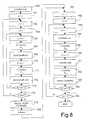
- Figure 8 shows a flowchart of the sequence of steps performed using a multi-resolution filter with a preset arbitrary number of splittings into subspaces.
- the samples of the input signal s i ( t ) are loaded, step 160; then a space split counter j is initialized at -1, step 161, and incremented by one unit, step 162; a subspace counter k is initialized at zero, step 163, and incremented by one unit, step 164. Then the samples of the input signal s i ( t ) are filtered using the filter H 0 jk (thus, at the first iteration, using the filter H 001 ) , step 165, and the filtered samples are downsampled, step 166.
- step 170 the samples of the input signal s i ( t ) are filtered using the filter H 1 jk (thus, at the first iteration, using the filter H 102 ), step 171, and the filtered samples are downsampled, step 172.
- step 174 it is checked whether the splitting into subspaces is terminated (i.e., whether the space split counter j has reached the preset maximum), step 174. If it has not, the procedure returns to step 162; if it has, all the obtained sample sequences are filtered using the neuro-fuzzy filter of Figure 1, step 175.
- the space split counter j is initialized at its maximum value plus one unit, step 180, and then decreased by one unit, step 181, the subspace counter k is initialized at zero, step 182, and incremented by one unit, step 183.
- the first sample sequence at output of the first neuro-fuzzy filter 120, in Figure 7) is upsampled, step 184, and filtered using a filter G 0jk (thus, at the first iteration, using the filter G 021 ), step 185.
- step 190 a second sample sequence at the output of a second neuro-fuzzy filter (121, in Figure 7) is upsampled, step 191, and filtered using a filter G 1jk (thus, at the first iteration, using the filter G 121 ), step 192.
- the samples at the output of the filters G 0jk and G 1jk are then summed, step 193.
- step 194 It is then checked whether the subspace counter k is equal to 2 ( j +1) , step 194; if it is not, the cycle comprising steps 183-193 is repeated (processing the sample sequences at the output of the subsequent neuro-fuzzy filters); if it is (output YES from step 194), it is checked whether the end has been reached, step 195; if it has not, the procedure returns to step 181, decreasing the space split counter j and processing the sample sequences previously upsampled, filtered and summed. The loop defined by steps 181-194 is repeated until a single sequence of samples is obtained, corresponding to the output signal S o ( t ), output YES from step 195.
- FIG. 9 shows the hardware implementation of the neuro-fuzzy filter 1 of Figure 1.
- the neuro-fuzzy filter 1 comprises a data memory 200, three work memories 201-203, a signal features calculation module 205, a control unit 206, a first-layer output memory unit 207, a second-layer output calculating unit 208, a reconstruction-weight calculating unit 209, and a reconstruction unit 210.
- the data memory 200 stores the (2 N + 1) samples e ( i ) of each work window and comprises (2 N + 1) registers, each having 16 bits.
- the work memories 201-203 are nonvolatile memories, for example ROM, PROM, EPROM, EEPROM or flash memories.
- the first work memory 201 stores the first signal feature X 1( i ) and comprises (2 N + 1) sixteen-bit memory locations. Since the value of the first signal feature X 1( i ) for the i -th sample is constant in the various sample windows, as is evident from equation (1), the contents of the first work memory 201 must not be modified during the learning step or during operation of the neuro-fuzzy filter 1, and the first work memory 201 may be implemented using any one of the technologies referred to above.
- the second work memory 202 stores the values of the two gaussian curves described by equation (2) according to the values of the signal features X 1, X 2, and X 3. Since the values of these gaussian curves depend upon the second-layer weights W m ( l , k ) , W v (l, k ), when a learning step is provided, the second work memory 202 must be of the programmable type, for example of the EPROM, EEPROM or flash type. To avoid the use of a memory of excessive size, the gaussian functions (which represent the membership functions of the signal features X 1, X 2, X 3, as discussed above) are stored as discrete values, according to the desired level of accuracy.
- the second work memory 202 must have a storage capacity of 256 x 16 x 6 bits.
- the second work memory 202 is then addressed starting from the current values (corresponding to the i -th sample) of the signal features X 1, X 2, X 3 supplied by the first work memory 201 and by the signal features calculation module 205, and outputs (to the first-layer output memory unit 207) the values of the six first-layer outputs oL 1 ( m ).
- the third work memory 203 stores the second-layer weights W FA ( m , n ) and the third-layer weights W DF ( n ). Since the third-layer weights W DF ( n ) are generally modified during the learning step, the third work memory 203 is of a programmable type, as is the second work memory 202. In detail, if there are M x N second-layer weights W FA ( m , n ) and N third-layer weights W DF ( n ), the work memory 203 comprises (16 x M x N + 16 x N ) bits.
- the signal features calculation module 205 comprises a hardware network (not shown) represented as divided into a first part 205a for calculating the second signal feature X 2 ( i ) and a second part 205b for calculating the third signal feature X 2 ( i ).
- this module comprises a sample memory (having 2 N + 1 locations), a unit for calculating the average value av, a unit for calculating the maximum of the differences between all the input samples and the central sample max ( diff ), a unit for calculating the maximum of the differences between all the input samples and the average value max ( diff_av ), and a unit for calculating the fractions defined by equations (2) and (3).
- the first-layer output memory unit 207 comprises six registers 212 which store the first-layer outputs oL 1 ( m ) supplied by the second work memory 202.
- the second-layer output calculating unit 208 comprises two modules, namely, a first multiplication module 208a and a minimum module 208b.
- the first multiplication module 208a includes six first multiplication units 213 each of which multiplies a respective first-layer output oL 1( m ) (supplied by the first-layer output memory unit 207) by n respective second-layer weights W FA ( m, n ) (supplied by the second work memory 203);
- the second multiplication module 208b includes six minimum units 214 which, starting from the six respective products oL 1( m ) x W FA ( m, n ), calculate the minimum thereof, supplying at the output a respective second-layer output oL 2( n ).
- the reconstruction-weight calculating unit 209 comprises two modules, namely, a second multiplication module 209a and a defuzzification module 209b.
- the second multiplication module 209a includes six second multiplication units 215 which multiply a respective second-layer output oL 2( n ), supplied by the second-layer output calculating unit 208, by a respective third-layer weight W DF ( n ), supplied by the third work memory 203.
- the defuzzification module 209b calculates the reconstruction weights oL 3, adding the products supplied by the second multiplication module 209a, adding together the second-layer outputs oL 2( n ), and calculating the ratio between the two sums in accordance with equation (6).
- the reconstruction unit 210 stores the reconstruction weights oL 3( i ) as these are supplied by the reconstruction-weight calculating unit 209 and, as soon as it has stored 2 N + 1 reconstruction weights oL 3, it calculates the output sample u (2 N + 1) in accordance with equation (7), also using the values of the 2 N + 1 samples supplied by the data memory 200. Subsequently, upon receipt of the next reconstruction weight oL 3(2 N + 2), it calculates the output sample u (2 N + 2) using also the previous 2 N reconstruction weights oL 3 and as many samples coming from the data memory 200, in accordance with equation (7).
- the control unit 206 determines the processing sequence and data loading/transfer between the various units and modules. To calculate a single output sample, the control unit repeats the sequence of steps of the fuzzy algorithm 2 N + 1 times, updates the data memory 200 at the end of 2 N + 1 cycles, and controls loading of successive 2 N + 1 samples.
- the method and filter reduce the noise of the input signal, whether the noise in question is of a white type or of a colored type, and enable separation of signals having different features.
- the filter preserves the steep edges of the signals without causing any losses of signal features, as is evident from a comparison between Figures 10a, 10b, and 10c.
- Figure 10a is a plot of a non-noisy voice signal (namely, a signal fragment corresponding to the vowel "e", with sampling at 44.1 kHz and a 16-bit A-D conversion resolution);
- Figure 10b is a plot the same signal as in Figure 10a, in presence of white noise;
- Figure 10c shows the result of filtration of the signal of Figure 10b using the filter device 95 of Figure 7.
- the filter can be trained, it can be adapted to a specific type of initial signal and can be subsequently modified if so required.
- the filter can be initially adapted to a first type of acoustic signal (for instance, a male voice with white noise, training being performed with two signals, one in the presence of white noise and one in the absence of noise).
- the learning step can be repeated for signals of a different type, for example a female voice.
- the new weights thus calculated can replace the previous ones or be stored in addition to the previous ones; in the latter case, the control unit 206 controlling the filter 1 can control sending, to the units 207-209 ( Figure 9), either of the first or of the second samples according to the use of the filter.
Abstract
The filtering device (80) comprises a neuro-fuzzy filter (1;
80) and implements a moving-average filtering technique in
which the weights for final reconstruction of the signal
(oL3 (i)) are calculated in a neuro-fuzzy network (3)
according to specific fuzzy rules. The fuzzy rules operate
on three signal features (X1(i), X2(i), X3(i)) for each
input sample (e(i)). The signal features are correlated to
the position of the sample in the considered sample window,
to the difference between a sample and the sample at the
center of the window, and to the difference between a sample
and the average of the samples in the window. The filter
device for the analysis of a voice signal comprises a bank
of neuro-fuzzy filters (86, 87). The signal is split into a
number of sub-bands, according to wavelet theory, using a
bank of analysis filters including a pair of FIR QMFs (H 0,
H 1) and a pair of downsamplers (85, 86); each sub-band signal
is filtered by a neuro-fuzzy filter (86, 87), and then the
various sub-bands are reconstructed by a bank of synthesis
filters including a pair of upsamplers (88, 89), a pair of
FIR QMFs (G 0, G 1), and an adder node (92).
Description
The present invention refers to a filtering device and
method for reducing noise in electrical signals, in
particular acoustic (voice) signals and images.
As is known, filters operating according to various linear
and nonlinear techniques are used to remove undesired
components from electrical signals. In particular, undesired
components may be any type of noise (white noise, flicker,
etc.) or other types of superimposed acoustic or visual
signals.
Linear filters are at present the most widely used
instruments for filtering noise. Finite-impulse filters
(FIRs) eliminate all the harmonics of a signal having a
frequency higher than the cutoff frequency of the filter and
improve the signal-to-noise ratio (SNR). Another linear
filtering technique is based on the fast Fourier transform
(FFT), where the signal is transformed into the frequency
domain, the undesired harmonics are removed, and then the
inverse Fourier transform is calculated.
As far as nonlinear techniques are concerned, average
filters are simple to design and may be implemented through
simple hardware circuits. Average filters are based on the
comparison of the individual signal samples in an time
interval with the average of all the samples in the same
time interval. On the basis of this comparison, the
individual samples are selectively attenuated.
All these methods share the disadvantage that, when removing
the noise, also some of the components of the original
signal are removed.
Furthermore, none of the current techniques, whether linear
or nonlinear ones, including average filtering, is able to
preserve steep edges of the signal. If a moving-average
filter is used, the width of the window must be very small
if steep edges are to be preserved. However, if the size of
the window becomes small, there is no significant reduction
in noise energy. If linear filters are used, all the
frequencies above the cutoff frequency are eliminated, with
consequent marked distortion of the signal.
The aim of the invention is thus to provide a filtering
method and device that does not cause a sensible
deterioration of the signal and at the same time preserves
the edges of the signal.
According to the present invention a device and method are
provided for filtering electrical signals, as respectively
defined in Claim 1 and Claim 24.
The filter and the method described are particularly useful
in the case of signals having steep edges, for which the aim
is to preserve the edges of the signals. Furthermore, it is
possible to filter signals affected by white and non-white
noise, such as flicker noise. Through the present method it
is moreover possible to eliminate from a signal other
signals that are superimposed on it and are characterized by
a wide spectral range.
The device and the method described are based upon a neuro-fuzzy
network. They are implemented with a moving-average
filtering technique in which the weighting factors (or
weights) for the final reconstruction of the signal are
calculated in a neuro-fuzzy network according to specific
fuzzy rules. This enables a better reduction of the noise.
The fuzzy rules operate on different variables, referred to
as signal features. Described hereinafter are three signal
features and six fuzzy rules.
The proposed filter is suitable for visual signals or
acoustic signals, even ones with sudden variations. Various
types of functions or signal features can be used to create
the rules. With the method described, the signal features
are correlated to the position of the sample in the
considered sample window, to the difference between a given
sample and the sample at the center of the window, and to
the difference between a given sample and the average of
samples in the window. These signal features may have a
considerable influence on the values of the weights for the
reconstruction of the signal; in addition, they may be
calculated in a relatively simple manner.
The method and the filter according to the invention
moreover comprise a neuro-fuzzy filter bank. In this way,
the signal may be split into different sub-bands according
to wavelet theory: each sub-band signal may be filtered by a
neuro-fuzzy network, and then the various sub-bands can be
reconstructed by the synthesis filter bank. As is known from
wavelet theory, in the first sub-band the signal features
have a low frequency, whereas in the last sub-band the
signal features have the maximum frequency. If non-white
noise (colored noise) is to be removed, this is approximated
by white noise in each individual sub-band. Given that a
neuro-fuzzy network works well on white noise, this solution
leads to a sensible reduction in noise.
The network is trained by supplying some configurations of
input and output signals (the configuration of the output
signal that it is required to obtain as a result of the
network evolution is called target configuration). The
training algorithm is based upon one of the known learning
methods, such as gradient descent, a genetic algorithm, the
simulated annealing method, random search, or any other
method for function optimization.
For an understanding of the present invention, preferred
embodiments thereof are now described, purely to furnish
non-limiting examples, with reference to the attached
drawings, in which:
- Figure 1 is a block diagram showing the general architecture of the filter according to the invention;
- Figure 2 represents the topology of a block of Figure 1 for a neuro-fuzzy network;
- Figures 3a and 3b show a flowchart of the operations performed by the filter of Figure 1;
- Figure 4 shows a block diagram of a filtering device using the filter of Figure 1;
- Figure 5 shows the transfer functions of digital filters belonging to the filtering device of Figure 4;
- Figure 6 shows the block diagram of some digital filters belonging to the filtering device of Figure 4;
- Figure 7 shows a block diagram of another filtering device using the filter of Figure 1;
- Figure 8 shows a flowchart of the operation of the filtering device of Figure 7;
- Figure 9 shows a block diagram for the hardware implementation of the filter of Figure 1; and
- Figures 10a, 10b, and 10c respectively show a voice signal free from noise, the same signal superimposed on white noise, and the same signal after filtering according to the invention.
Figure 1 shows a filter 1 comprising a signal-feature
computation unit 2, a neuro-fuzzy network 3, a
reconstruction unit 4, and a training unit 5.
The signal-feature computation unit 2 receives at the input
a signal In including of a plurality of input samples e(i),
stores, at each clock cycle, (2N + 1) input samples e(i)
(which represent a work window for filter 1) in an internal
buffer, computes the signal features X1(i), X2(i), and X3(i)
for each input sample e(i) on the basis of all the input
samples belonging to the work window (as described in detail
hereinafter), and supplies the signal features X1(i),
X2(i), and X3(i) thus calculated to the neuro-fuzzy network
3.
The neuro-fuzzy network 3 processes the signal features
X1(i), X2(i), and X3(i) and generates at the output a
reconstruction weight oL3(i) for each input sample e(i). To
this aim, starting from the signal features X1(i), X2(i),
and X3(i) and for each input sample e(i), the neuro-fuzzy
network 3 first performs a fuzzification operation, then
applies preset fuzzy rules, and finally carries out a
defuzzification operation. The reconstruction weight oL3(i)
thus obtained is hence the weighted sum of all the input
samples e(i) in the same work window, as explained in detail
hereinafter with reference to Figures 2 and 3.
The reconstruction unit 4 receives the reconstruction
weights oL3(i) and the input samples e(i) and, after
accumulating a sufficient number of input samples e(i) and
of corresponding reconstruction weights oL3(i), generates an
output sample u(i) the sequence of which forms an output
signal Out.
The training unit 5 is operative only initially, so as to
train the neuro-fuzzy network 3 and modify the weights of
the network with the aim of obtaining an optimal behavior of
the filter 1, as described in detail hereinafter.
The signal features X1(i), X2(i), and X3(i), computed in the
signal-feature computation unit 2, are correlated,
respectively, to the distance between each sample and the
central sample of the considered window, to the difference
between a given sample and the sample at the center of the
window, and to the difference between a given sample and the
average of samples in the window, and are normalized so as
to obtain values between 0 and 1.
In detail, given a window of (2N + 1) input samples e(i),
with i = 0, ..., 2N, the signal features X1(i), X2(i), and
X3(i) for each input sample e(i) are defined as
X 1(i )= i -N N
X 2(i )= e (i )-e (N ) max(diff )
X 3(i )= e (i )-av max(diff _av )
where N is the position of a central sample e(N) in the work
window;
max (diff) = max (e(k)-e(N)) with k = 0, ..., 2N, i.e., the maximum of the differences between all the input samples e (k) and the central sample e(N);
av is the average value of the input samples e(i); and
max (diff_av) = max (e(k)-av) with k = 0, ..., 2N, i.e., the maximum of the differences between all the input samples e(k) and the average value av.
The neuro-fuzzy network 3 is a three-layer fuzzy network the
functional representation of which appears in Figure 2, in
which, for reasons of simplicity, the index i in parenthesis
for the specific sample within the respective work window is
not indicated. Nevertheless, as mentioned above, and as will
emerge more clearly from the flowchart of Figures 3a, 3b,
the neuro-fuzzy processing represented by Figure 2 is
repeated for each input sample e(i).
In detail, starting from the three signal features X1, X2
and X3 (or generically from 1 signal features X1) and given
k membership functions of a gaussian type for each signal
feature (described by the average value Wm (l, k) and by the
variance Wv (l, k), a fuzzification operation is performed in
which the membership level of the signal features X1, X2 and
X3 is evaluated with respect to each membership function
(here two for each signal feature, so that k = 2; in all
there are M = 1 x k = 6 membership functions).
In Figure 2, the above operation is represented by six
first-layer neurons 6, each of which, starting from the
three signal features X1, X2 and X3 (generically designated
by X1) and using as weights the average value Wm (l, k) and
the variance Wv (l, k) of the membership functions, supplies a
first-layer output oL1(l, k) (hereinafter also designated by
oL1(m)) calculated as follows:
 Hereinafter, a fuzzy AND operation is performed, using the
norm of the minimum, in such a way as to obtain N second-layer
outputs oL2 (n). For example, N is equal to 6. As is
known, a fuzzy AND operation using the norm of the minimum
is based upon rules of the type:
Hereinafter, a fuzzy AND operation is performed, using the
norm of the minimum, in such a way as to obtain N second-layer
outputs oL2 (n). For example, N is equal to 6. As is
known, a fuzzy AND operation using the norm of the minimum
is based upon rules of the type:
...
In practice, with the neuro-fuzzy network of Figure 2, each
second-layer output oL2(n) is equal to the minimum one among
the products of the M outputs oL1(m) of the first-layer
neurons 6 and a respective second-layer weight WFA (m, n).
In Figure 2 the above operation is represented by N second-layer
neurons 7 which implement the equation

Finally, the third layer corresponds to a defuzzification
operation and supplies at output a discrete-type
reconstruction weight oL3, using N third-layer weights
WDF (n). The defuzzification method is that of the center of
gravity (centroid) and is represented in Figure 2 by a
third-layer neuron 8 supplying the reconstruction weight oL3
according to the equation

The reconstruction unit 4 then awaits a sufficient number of
samples e(i) and corresponding reconstruction weights oL3(i)
(at least 2N + 1, corresponding to the width of a work
window) and calculates an output sample u(i) as the weighted
sum of the input samples e(i - j), with j = 0 ... 2N, using
the reconstruction weights oL3 (i - j), according to the
equation

The training unit 5 operates only in an initial learning
stage, when an input signal In having a known configuration
is supplied to the filter 1, the output signal Out obtained
is compared with a target signal Tg, and the distance
between the obtained signal Out and the target signal Tg is
evaluated on the basis of a fitness function. This fitness
function may be, for example, the quadratic signal/noise
ratio having the following expression:
 in which T is the total number of input samples e(i).
Using the fitness function and applying a method for
function optimization, such as the gradient-descent method,
a genetic algorithm, the simulated-annealing method, and
random search, the first-layer weights (mean value Wm (l, k)
and variance Wv (l, k) of the gaussian membership functions)
and the third-layer weights WDF (n) are modified, and a new
fitness evaluation is performed. The second-layer weights
WFA (m, n) are instead randomly initialized and are not
modified. The learning process is iterated until a preset
value of the fitness function is achieved or until a preset
number of genetic algorithms have been generated or a preset
number of steps of the selected optimization algorithm has
been performed.
In this way, the neuro-fuzzy network 3 implements an
adaptive algorithm and overcomes the limitations of neural
networks or of fuzzy systems considered separately. In fact,
fuzzy systems do not have learning capabilities and, if the
selection of the fuzzy rules is not accurate, the fuzzy
algorithm does not behave satisfactorily. Instead, using the
neuro-fuzzy network 3 and carrying out a prior learning step
it is possible to approach a signal having a complex
mathematical structure, for example the voice in a noisy
environment, without any prior knowledge of the mathematical
laws governing the said system.
Operation of the filter 1 of Figure 1 is described in detail
hereinafter with reference to Figures 3a and 3b.
Initially, the filter 1 is initialized, step 10, as is a
window counter p, step 11. Then the window counter p is
incremented by (2N + 1), equal to the number of input
samples e(i) in a work window, step 12, and the input
samples of a work window ranging between e(p) and e(p + 2N)
are loaded, step 13. A sum-of-samples counter h is
initialized at 0, and a sum-of-samples variable S(0) is
initialized with the value of the input sample e(p), step
14. Next, the sum-of-samples counter h is incremented by one
unit, step 15, and the sum-of-samples variable S(h) is
incremented with the value of a sample e(p + h), step 20.
After the sum of (2N + 1) input samples (output YES from
step 21), the sum-of-samples variable S(h) is equal to the
sum of all the input samples e(i) and may be directly used
for calculating the signal features.
Subsequently, using equations (1), (2) and (3) and the value
of the sum-of-samples variable S(h), the signal features X1,
X2, X3 are calculated for each sample e(p) - e(p + 2N)
belonging to the considered work window, step 22. A sample
counter i for the input samples within the considered work
window is then reset to zero, step 23, and subsequently
incremented by one unit, step 24; a feature counter l for
the number of signal features used (in the present case, 3)
is reset to zero, step 25, and subsequently incremented,
step 26; and a function counter k for the number of
membership functions used for each signal feature (in the
present case, 2) is reset to zero, step 30, and subsequently
incremented, step 31. Next, the first-layer weights (the
mean value Wm (l, k) and the variance Wv (l, k)) are loaded,
step 32, and the first-layer outputs oL1(l, k) are
calculated in accordance with equation (4), step 33.
Loading of the first-layer weights Wm (l, k), Wv (l, k) and
calculation of the first-layer outputs oL1 (l, k) are
repeated for all the membership functions (output YES from
step 34) and for all the signal features (output YES from
step 35).
Next, a second-layer neuron counter n is reset to zero, step
39, and incremented by one unit, step 40; an algorithm
counter m is reset to zero, step 41, and incremented, step
42; and the second-layer weights WFA (m, n) for the n-th
second-layer neuron 7 are loaded, steps 43, 44. Then, the
second-layer output oL2(n) for the n-th second-layer neuron
7 is calculated using equation (5), step 45, and the
procedure of steps 40-45 is repeated for all the n second-layer
neurons 7.
At the end (output YES from step 50), the second-layer
neuron counter n is reset again, step 51, and incremented by
one unit, step 52; all the third-layer weights WDF (n) are
loaded in succession, steps 53, 54; at the end of loading
(output YES from step 54) the reconstruction weight oL3(i)
is calculated in accordance with equation (6), step 55.
The reconstruction weights oL3(i) thus calculated and the
respective input samples e(i) are stored, step 60, and the
procedure described for steps 24-60 is repeated for
successive input samples e(i) until (2N + 1) input samples
e(i) are reached (output YES from step 61).
Next, a sum counter j is reset to zero, step 62, and the
input sample e(i) is added to the previous 2N input samples
e(i - j), and the sum is stored in a variable E, step 63.
After the sum of (2N + 1) input samples has been carried
out, an output sample u(i) is calculated in accordance with
equation 7, step 65.
The entire cycle described by steps 12-65 is repeated as
long as input samples e(i) are present; at the end (output
YES from step 70), the sample processing procedure
terminates.
According to another aspect of the invention, filtering is
based on a multi-resolution analysis obtained through a
filter bank in phase quadrature. Wavelet theory furnishes
the theoretical basis for multi-resolution.
As is known, a multi-resolution analysis defines a set of
nested subspaces of a square summable function space, i.e.,
the space of the finite-energy functions, widely known in
physics and electrical engineering. On the basis of the
above analysis, a projection of a function in one of these
subspaces isolates the "roughest" details of the function,
whilst projection of the function in the orthonormal
complement of this subspace isolates the "finer" details of
the function. The procedure may be iterated to obtain a
pyramid. From wavelet theory it is known that the operation
may be performed using a bank of FIR filters, in which each
FIR filter is followed by a subsampler). The signal thus
split into sub-bands can be reconstructed using a bank of
complementary filters, each of which is provided with a
sample incrementer (upsampler).
A first embodiment of the above-mentioned solution is shown
in Figure 4 and regards a multi-resolution filter 80
generating two subspaces and using a first pair of Finite
Impulse Response Quadrature Mirror Filters (FIR QMFs) for
the analysis and a second pair of FIR QMFs for the
synthesis.
In detail, the multi-resolution filter 80 receives, on an
input 81, an input signal si (t). The input signal si (t) is
supplied to two input FIR filters H 0, H 1 which perform a
convolution operation so to output a corresponding filtered
signal  ,
,  equal to:

 in which M is the order of the filters H 0, H 1;
  ,
,  is the t-th sample of the respective output sequence; si (t)
is the t-th sample of the input sequence; h0 (r), h1 (r) is the
t-th tap of the input FIR filter H 0, H 1, in which
is the t-th sample of the respective output sequence; si (t)
is the t-th sample of the input sequence; h0 (r), h1 (r) is the
t-th tap of the input FIR filter H 0, H 1, in which
h1 (r ) = (-1) r -1 h 0 (2I - r + 1)
where I is an integer.
The input FIR filters H 0, H 1 have transfer functions shown in
Figure 5 and thus define, respectively, a low-pass filter
and a high-pass filter, and have the structure shown in
Figure 6, where the generic tap h(r) corresponds to h 0(r) or
to h1 (r), according to whether it is the input FIR filter H 0
or the input FIR filter H 1.
The outputs of the input FIR filters H 0, H 1 are each
connected to a respective subsampling unit 84, 85 which
discards the odd samples from the input signal  ,
,  and retains only the even samples, generating a respective
signal e 0(t), e 1(t). The outputs of the
and retains only the even samples, generating a respective
signal e 0(t), e 1(t). The outputs of the subsampling units 84,
85 are each connected to a respective neuro- fuzzy filter 86,
87. Both of the neuro- fuzzy filters 86, 87 have the
structure shown in Figure 1.
The output signals u 0(t), u 1(t) of the neuro- fuzzy filters
86, 87 are each supplied to a respective upsampler 88, 89
which generates a respective output signal u 0 u (t), u 1 u (t) by
entering a zero sample between each pair of samples of the
respective output signal u 0(t), u 1(t) of the neuro- fuzzy
filters 86, 87. The outputs of the of the upsampling units
88, 89 are each connected to a respective output FIR filter
G 0, G 1. These filters too have each a respective transfer
function given by equation (9) and equation
(10), respectively.
Finally, the output signals of the output FIR filters G 0, G 1
are added together, sample by sample, by an adder 92.
Figure 7 shows a multi-resolution filter 95 using eight
subspaces. In detail, the input signal si (t) is initially
supplied to two first synthesis FIR filters H 001, H 102,
respectively of the low-pass type and of the high-pass type,
and is then subsampled in two first subsampling units 96,
97, in a similar way as described for the units 85, 86 of
Figure 4. The sequences of samples thus obtained are each
supplied to two synthesis filters (and hence altogether to
four second synthesis FIR filters H 011, H 112, H 013, and H 114).
The outputs of the second synthesis FIR filters H 011, H 112,
H 013, and H 114 are then supplied to four second subsampling
units 100-103, and each sequence thus obtained is supplied
to two third synthesis FIR filters (and hence altogether to
eight third synthesis FIR filters H 021, H 122, H 023, H 124, H 025,
H 126, H 027, H 128), generating eight sequences of samples. The
eight sample sequences are then supplied to eight third
subsampling units 107-114 and processed in respective neuro-fuzzy
filters 120-127 having the structure illustrated in
Figure 1. The sample sequences present on the outputs of the
neuro-fuzzy filters 120-127 are then incremented via
upsampling units 130-137 and supplied to respective first
synthesis FIR filters G 021, G 122, G 023, G124, G 025, G 126, G 027, and
G 128. The sample sequences thus obtained are added up two by
two through four adders 140-143 (with a reverse process with
respect to the one followed downstream of the second
subsampling units 100-103), supplied to four upsampling
units 146-149, and filtered again through four second
synthesis FIR filters G 011, G 112, G 013, and G 114.
The sample sequences thus obtained are added up two by two
through two adders 150, 151 (according to a reverse process
with respect to the one followed downstream of the first
subsampling units 96, 97), incremented by two upsampling
units 154, 155, filtered through two third synthesis FIR
filters G 001 and G 102, and finally summed in an adder 160 so
as to supply the output signal s o (t).
Figure 8 shows a flowchart of the sequence of steps
performed using a multi-resolution filter with a preset
arbitrary number of splittings into subspaces.
Initially, the samples of the input signal si (t) are loaded,
step 160; then a space split counter j is initialized at -1,
step 161, and incremented by one unit, step 162; a subspace
counter k is initialized at zero, step 163, and incremented
by one unit, step 164. Then the samples of the input signal
si (t) are filtered using the filter H 0 jk (thus, at the first
iteration, using the filter H 001), step 165, and the filtered
samples are downsampled, step 166. Next, the subspace
counter k is incremented, step 170; the samples of the input
signal si (t) are filtered using the filter H 1 jk (thus, at the
first iteration, using the filter H 102), step 171, and the
filtered samples are downsampled, step 172.
It is checked whether the subspace counter k is equal to
2( j +1); if it is not, the cycle comprising steps 164-172 is
repeated (in the iterations following on the first,
filtering is performed on the samples obtained in the
previous iteration with the filter H 0( j -1)( k -2) or H 1( j -1)( k -2)) ; if
it is (output YES from step 173) , it is checked whether the
splitting into subspaces is terminated (i.e., whether the
space split counter j has reached the preset maximum), step
174. If it has not, the procedure returns to step 162; if it
has, all the obtained sample sequences are filtered using
the neuro-fuzzy filter of Figure 1, step 175.
Next, the space split counter j is initialized at its
maximum value plus one unit, step 180, and then decreased by
one unit, step 181, the subspace counter k is initialized at
zero, step 182, and incremented by one unit, step 183. Next,
the first sample sequence at output of the first neuro-fuzzy
filter (120, in Figure 7) is upsampled, step 184, and
filtered using a filter G0jk (thus, at the first iteration,
using the filter G 021), step 185. Then, the subspace counter
k is incremented again, step 190; a second sample sequence
at the output of a second neuro-fuzzy filter (121, in Figure
7) is upsampled, step 191, and filtered using a filter G1jk
(thus, at the first iteration, using the filter G 121), step
192. The samples at the output of the filters G0jk and G1jk
are then summed, step 193.
It is then checked whether the subspace counter k is equal
to 2( j +1), step 194; if it is not, the cycle comprising steps
183-193 is repeated (processing the sample sequences at the
output of the subsequent neuro-fuzzy filters); if it is
(output YES from step 194), it is checked whether the end
has been reached, step 195; if it has not, the procedure
returns to step 181, decreasing the space split counter j
and processing the sample sequences previously upsampled,
filtered and summed. The loop defined by steps 181-194 is
repeated until a single sequence of samples is obtained,
corresponding to the output signal So (t), output YES from
step 195.
Figure 9 shows the hardware implementation of the neuro-fuzzy
filter 1 of Figure 1. In detail, the neuro-fuzzy
filter 1 comprises a data memory 200, three work memories
201-203, a signal features calculation module 205, a control
unit 206, a first-layer output memory unit 207, a second-layer
output calculating unit 208, a reconstruction-weight
calculating unit 209, and a reconstruction unit 210.
The data memory 200 stores the (2N + 1) samples e(i) of each
work window and comprises (2N + 1) registers, each having 16
bits.
The work memories 201-203 are nonvolatile memories, for
example ROM, PROM, EPROM, EEPROM or flash memories.
In particular, the first work memory 201 stores the first
signal feature X1(i) and comprises (2N + 1) sixteen-bit
memory locations. Since the value of the first signal
feature X1(i) for the i-th sample is constant in the various
sample windows, as is evident from equation (1), the
contents of the first work memory 201 must not be modified
during the learning step or during operation of the neuro-fuzzy
filter 1, and the first work memory 201 may be
implemented using any one of the technologies referred to
above.
The second work memory 202 stores the values of the two
gaussian curves described by equation (2) according to the
values of the signal features X1, X2, and X3. Since the
values of these gaussian curves depend upon the second-layer
weights Wm (l, k), W v (l, k), when a learning step is provided,
the second work memory 202 must be of the programmable type,
for example of the EPROM, EEPROM or flash type. To avoid the
use of a memory of excessive size, the gaussian functions
(which represent the membership functions of the signal
features X1, X2, X3, as discussed above) are stored as
discrete values, according to the desired level of accuracy.
For example, if the membership functions have 256 values,
with an accuracy of 16 bits per value, considering two sets
of fuzzy rules for each signal feature X1, X2, and X3, the
second work memory 202 must have a storage capacity of
256 x 16 x 6 bits. The second work memory 202 is then
addressed starting from the current values (corresponding to
the i-th sample) of the signal features X1, X2, X3 supplied
by the first work memory 201 and by the signal features
calculation module 205, and outputs (to the first-layer
output memory unit 207) the values of the six first-layer
outputs oL1 (m).
The third work memory 203 stores the second-layer weights
WFA (m, n) and the third-layer weights WDF (n). Since the third-layer
weights WDF (n) are generally modified during the
learning step, the third work memory 203 is of a
programmable type, as is the second work memory 202. In
detail, if there are M x N second-layer weights WFA (m, n) and
N third-layer weights WDF (n), the work memory 203 comprises
(16 x M x N + 16 x N) bits.
The signal features calculation module 205 comprises a
hardware network (not shown) represented as divided into a
first part 205a for calculating the second signal feature
X2 (i) and a second part 205b for calculating the third
signal feature X2 (i). In the signal features calculation
module 205 the operations represented by equations (2) and
(3) are performed, and this module comprises a sample memory
(having 2N + 1 locations), a unit for calculating the
average value av, a unit for calculating the maximum of the
differences between all the input samples and the central
sample max (diff), a unit for calculating the maximum of the
differences between all the input samples and the average
value max (diff_av), and a unit for calculating the fractions
defined by equations (2) and (3).
The first-layer output memory unit 207 comprises six
registers 212 which store the first-layer outputs oL1 (m)
supplied by the second work memory 202.
The second-layer output calculating unit 208 comprises two
modules, namely, a first multiplication module 208a and a
minimum module 208b. In detail, the first multiplication
module 208a includes six first multiplication units 213 each
of which multiplies a respective first-layer output oL1(m)
(supplied by the first-layer output memory unit 207) by n
respective second-layer weights WFA (m, n) (supplied by the
second work memory 203); the second multiplication module
208b includes six minimum units 214 which, starting from the
six respective products oL1(m) x WFA (m, n), calculate the
minimum thereof, supplying at the output a respective
second-layer output oL2(n).
The reconstruction-weight calculating unit 209 comprises two
modules, namely, a second multiplication module 209a and a
defuzzification module 209b. In detail, the second
multiplication module 209a includes six second
multiplication units 215 which multiply a respective second-layer
output oL2(n), supplied by the second-layer output
calculating unit 208, by a respective third-layer weight
WDF (n), supplied by the third work memory 203. The
defuzzification module 209b calculates the reconstruction
weights oL3, adding the products supplied by the second
multiplication module 209a, adding together the second-layer
outputs oL2(n), and calculating the ratio between the two
sums in accordance with equation (6).
The reconstruction unit 210 stores the reconstruction
weights oL3(i) as these are supplied by the reconstruction-weight
calculating unit 209 and, as soon as it has stored
2N + 1 reconstruction weights oL3, it calculates the output
sample u(2N + 1) in accordance with equation (7), also using
the values of the 2N + 1 samples supplied by the data memory
200. Subsequently, upon receipt of the next reconstruction
weight oL3(2N + 2), it calculates the output sample
u(2N + 2) using also the previous 2N reconstruction weights
oL3 and as many samples coming from the data memory 200, in
accordance with equation (7).
The control unit 206 determines the processing sequence and
data loading/transfer between the various units and modules.
To calculate a single output sample, the control unit
repeats the sequence of steps of the fuzzy algorithm 2N + 1
times, updates the data memory 200 at the end of 2N + 1
cycles, and controls loading of successive 2N + 1 samples.
The advantages of the method and filter illustrated herein
are described below. First, the method and filter reduce the
noise of the input signal, whether the noise in question is
of a white type or of a colored type, and enable separation
of signals having different features. The filter preserves
the steep edges of the signals without causing any losses of
signal features, as is evident from a comparison between
Figures 10a, 10b, and 10c. In particular, Figure 10a is a
plot of a non-noisy voice signal (namely, a signal fragment
corresponding to the vowel "e", with sampling at 44.1 kHz
and a 16-bit A-D conversion resolution); Figure 10b is a
plot the same signal as in Figure 10a, in presence of white
noise; and Figure 10c shows the result of filtration of the
signal of Figure 10b using the filter device 95 of Figure 7.
Since the filter can be trained, it can be adapted to a
specific type of initial signal and can be subsequently
modified if so required. For example, the filter can be
initially adapted to a first type of acoustic signal (for
instance, a male voice with white noise, training being
performed with two signals, one in the presence of white
noise and one in the absence of noise). Then, the learning
step can be repeated for signals of a different type, for
example a female voice. The new weights thus calculated can
replace the previous ones or be stored in addition to the
previous ones; in the latter case, the control unit 206
controlling the filter 1 can control sending, to the units
207-209 (Figure 9), either of the first or of the second
samples according to the use of the filter.
Finally, it is clear that numerous variations and
modifications may be made to the method and filter described
and illustrated herein, all falling within the scope of the
invention, as defined in the annexed claims.
Claims (38)
- A filtering device (80; 95) for filtering signals having steep edges, characterized by at least one neuro-fuzzy filter (1).
- A filtering device according to Claim 1, characterized in that said neuro-fuzzy filter (1) comprises:a signal-feature calculating unit (2) receiving input samples (e(i)) of a signal (In) to be filtered and generating signal features (X1(i), X2(i), X3(i)) ;a neuro-fuzzy network (3) receiving said signal features and generating reconstruction weights (oL3(i)); anda moving-average reconstruction unit (4) receiving said input samples (e(i)) and said reconstruction weights (oL3(i)), and generating output samples (u(i)) from said input samples and said reconstruction weights.
- A filtering device according to Claim 2, characterized in that said signal-feature calculating unit (2) comprises a memory (200) storing a first plurality of input samples (e(i)) forming a first window, and a feature-calculating network (201, 205) receiving said first plurality of input samples and supplying a plurality of features (X1(i), X2(i), X3(i)) for each one of said input samples.
- A device according to Claim 3, characterized in that said feature-calculating network (201, 205) comprises first feature-providing means (201) which generate, for each of said input samples (e(i)), a first signal feature (X1(i)) correlated to a position of said input sample in said first window; second feature-providing means (205a) which generate, for each of said input samples (e(i)), a second signal feature (X2(i)) correlated to the difference between said input sample and a central sample (e(N)) in said first window; and third feature-providing means (205b) which generate, for each of said input samples (e(i)), a third signal feature (X3(i)) correlated to the difference between said input sample and an average sample value in said first window.
- A device according to Claim 4, characterized in that said first feature-providing means (201) generate said first signal feature (X1(i)) for an input sample (e(i)) according to the relation
- A device according to Claim 5, characterized in that said first feature-providing means comprise a first work memory (201) storing said first signal feature (X1(i)) for each one of said input samples (e(i)).
- A device according to any of Claims 4-6, characterized in that said second feature-providing means (205a) generate said second signal feature (X2(i)) for an input sample (e(i)) according to the relation
- A device according to any of Claims 4-7, characterized in that said third feature-providing means (205b) generate said third signal feature (X3(i)) for an input sample (e(i)) according to the relation
- A device according to any of Claims 2-8, characterized in that said neuro-fuzzy network (3) comprises:fuzzification neurons (6, 202) receiving said signal features (X1(i), X2(i), X3(i)) of an input sample (e(i)) and generating first-layer outputs (oL1) defining a confidence level of said signal features with respect to preset membership functions;fuzzy neurons (7) of an AND type, receiving said first-layer outputs and generating second-layer outputs (oL2) deriving from fuzzy rules; anda defuzzification neuron (8) receiving said second-layer outputs and generating a reconstruction weight (oL3) for each of said input samples (e(i)), using a center-of-gravity criterion.
- A device according to Claim 9, characterized in that said membership functions are gaussian functions, and said first-layer outputs are calculated according to the equationwherein oL1(l, k) is a first-layer output, X1 is a signal feature, Wm (l, k) is the mean value, and Wv (l, k) is the variance of a gaussian function.

- A filtering device according to Claim 9 or 10, characterized in that it comprises two membership functions for each one of said signal features (X1(i), X2(i), X3(i)).
- A filtering device according to any of Claims 9-11, characterized in that said first-layer neurons (6) comprise a second work memory (202) storing values of said first-layer outputs (oL1(l, k)) for each value of said signal features (X1(i), X2(i), X3(i)).
- A filtering device according to any of Claims 9-12, characterized in that said fuzzy rules are of an AND type, and said second-layer outputs (oL2) use the norm of the minimum.
- A filtering device according to Claim 13, characterized in that said second-layer outputs are calculated according to the equationwherein oL2(n) is a second-layer output; WFA (m, n) is a second-layer weight, and oL1(l, k) is a first-layer output.

- A filtering device according to Claim 14, characterized in that said second-layer neurons (7) comprise a plurality of multiplication units (213) and a plurality of minimum modules (214) cascade-connected together.
- A filtering device according to any of Claims 9-15, characterized in that said reconstruction weights are calculated according to the equationwherein oL3(n) is a reconstruction weight; WDF (n) are third-layer weights, and oL2(n) is a second-layer output.

- A filtering device according to any of Claims 9-16, characterized in that said moving-average reconstruction unit (4) receives a second plurality of input samples (e(i)) forming a second window, and a corresponding plurality of reconstruction weights (oL3(i)), and calculates each of said output samples (u(i)) according to the equationwherein e(i-j) is an (i-j) -th input sample, and oL3(i-j) is a reconstruction weight associated to an (i-j) -th input sample.

- A filtering device according to any of Claims 9-17, characterized by a training unit (5) having a first input connected to said moving-average reconstruction unit (4) and receiving said output samples (u(i)), a second input receiving a desired output signal (Tg), and an output connected to said neuro-fuzzy network (3) to supply optimized weighting values.
- A filtering device according to any of Claims 1-18, characterized by a first splitting stage (H 1, H 0, 84, 85; H 001, H 102, 96, 97) generating at least two streams of samples to be filtered; one said neuro-fuzzy filter (86, 87; 120-127) for each stream of samples to be filtered, each of said neuro-fuzzy filters generating a respective stream of filtered samples; and a first recomposition stage (88, 89, 92, G 0, G 1; 154, 155, 160, G 001, G 102) receiving said streams of filtered samples and generating a single stream of output samples (so ).
- A filtering device according to Claim 19, characterized by a plurality of further splitting stages (H 011-H 128, 100-114) cascade-connected together and to said first splitting stage (H 001, H 102, 96, 97), and a plurality of further recomposition stages (130-151, G 021-G 114) cascade-connected to each other between said neuro-fuzzy filters (120-127) and said first recomposition stage (154, 155, 160, G 001, G 102).
- A filtering device according to Claim 19 or 20, characterized in that said splitting stages (H 1, H 0, 84, 85; H 001 -H 128, 96-114) each comprise a first and a second analysis filters (H 1, H 0, H 001-H 128) in phase quadrature to each other and receiving a stream of samples to be split, said first and a second analysis filters generating a respected stream of split samples, and a first and a second downsampling unit (84, 85; 96-114), each of which receives a respective stream of split samples,
and in that said recomposition stages (88, 89, 92, G 0, G 1; 130-160, G 021-G 102) each comprise a first and a second upsampling units (88, 89; 130-137, 146-149, 154, 155), each first and a second upsampling units receiving a respective stream of samples to be incremented and generating a respective stream of incremented samples; a first and a second synthesis filters (G 0, G 1; G 021-G 102) in quadrature with to each other and complementary to said analysis filters, each of said first and a second synthesis filters receiving a respective stream of incremented samples and generating a respective stream of partial samples; and an adder node (92; 140-143, 150, 151, 160) receiving said streams of partial samples and generating a stream of added samples. - A filtering device according to Claim 21, characterized in that said analysis filters (H 1, H 0; H 001-H 128) are quadrature mirror filters (QMFs), and said synthesis filters (G 0, G 1; G 021-G 102) are QMFs complementary to said analysis filters.
- A filtering device according to Claim 22, characterized in that said quadrature mirror filters (H 1, H 0; H 001-H 128; G 0, G 1; G 021-G 102) are convolutive filters.
- A method for reducing noise in a filter having sharp edges, characterized by a neuro-fuzzy filtering step.
- A method according to Claim 24, characterized in that it comprises the steps of:calculating signal features (X1(i), X2(i), X3(i)) from input samples (e(i)) of a signal (In) to be filtered;calculating reconstruction weights (oL3) from said signal features using a neuro-fuzzy network (3); andreconstructing, from said input samples and said reconstruction weights and using a moving-average filter, an output signal (Out) including a plurality of output samples (u(i)).
- A method according to Claim 25, characterized by the steps of:storing a first plurality of input samples (e(i)) forming a first window; andcalculating, from said first plurality of input samples, a plurality of signal features (X1(i), X2(i), X3(i)) for each of said input samples.
- A method according to Claim 26, characterized in that said step of calculating a plurality of signal features for each of said input samples comprises the steps of:calculating a first signal feature (X1(i)) correlated to a position of said input sample (e(i)) in said first window;calculating a second signal feature (X2(i)) correlated to the difference between said input sample and a central sample in said first window; andcalculating a third signal feature (X3(i)) correlated to the difference between said input sample and an average sample value av in said first window.
- A method according to Claim 26 or 27, characterized in that said step of calculating reconstruction weights (oL3) comprises the steps of:performing a fuzzification operation and calculating first-layer outputs (oL1) defining confidence levels of said signal features (X1(i), X2(i), X3(i)) with respect to preset membership functions;performing a fuzzy AND operation and generating second-layer outputs (oL2) deriving from fuzzy rules, starting from said first-layer outputs; andperforming a defuzzification operation on said second-layer outputs and generating a reconstruction weight (oL3) for each one of said input samples (e(i)), using a center-of-gravity criterion of the.
- A method according to Claim 28, characterized in that said membership functions are gaussian functions, and said first-layer outputs are calculated according to the equationwherein oL1(l, k) is a first-layer output, X1 is a signal feature, Wm (l, k) is the mean value, and Wv (l, k) is the variance of a gaussian function.

- A method according to Claim 28 or 29, characterized in that said second-layer outputs are calculated according to the equationwherein oL2(n) is a second-layer output; WFA (m, n) is a second-layer weight, and oL1(l, k) is a first-layer output.
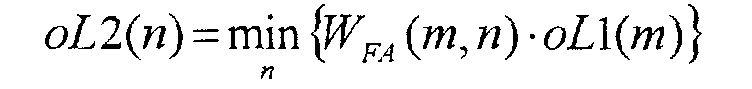
- A method according to any of Claims 28-30, characterized in that said reconstruction weights are calculated according to the equationwherein oL3 is a reconstruction weight; WDF (n) are third-layer weights, and oL2(n) is a second-layer output.

- A method according to any of Claims 26-31, characterized in that said step of reconstructing using a moving-average filter comprises the steps of:wherein e(i-j) is an (i-j) -th input sample, and oL3 (i-j) is a reconstruction weight associated to an (i-j)-th input sample.receiving a second plurality of input samples (e(i)) forming a second window, and a respective plurality of reconstruction weights (oL3(i)); andcalculating each of said output samples according to the equation

- A method according to any of Claims 24-32, characterized by a training step for training weights used in said neuro-fuzzy filtering step.
- A method according to Claim 33, characterized in that said training step comprises the steps of:generating an input signal having a known configuration;filtering said input signal having a known configuration to obtain a test output signal;comparing said test output signal with a desired signal (Tg) to obtain a distance between said test output signal and said desired signal;calculating a fitness function from said distance; andoptimizing said weights in accordance with said fitness function.
- A method according to any of Claims 26-34, characterized by a multiresolution analysis whereby the signal is splitted into sub-bands through orthonormal wavelets.
- A method according to Claim 35, characterized by the steps of:splitting a stream of input samples into at least two streams of samples to be filtered;filtering each stream of samples to be filtered using a respective neuro-fuzzy filter (86, 87; 120-127) to obtain at least two streams of filtered samples; andrecomposing said streams of filtered samples to generate a single stream of output samples (so ).
- A method according to Claim 36, characterized in that, before performing said step of filtering, said step of splitting is repeated a preset number of times, and in that, after performing said step of filtering, said step of recomposing is repeated said preset number of times.
- A method according to Claim 36 or 37, characterized in that said step of splitting comprises the steps of:and in that said step of recomposing comprises the steps of:feeding a stream of samples to be split to two analysis filters in phase quadrature to each other;generating two streams of filtered split samples; anddownsampling said streams of filtered split samples,upsampling streams of samples to be incremented, generating streams of incremented samples;filtering said streams of incremented samples using two synthesis filters in phase quadrature to each other and complementary to said analysis filters, generating streams of partial samples; andadding pairs of streams of partial samples and generating a stream of added samples.
Priority Applications (2)
| Application Number | Priority Date | Filing Date | Title |
|---|---|---|---|
| EP00830782A EP1211636A1 (en) | 2000-11-29 | 2000-11-29 | Filtering device and method for reducing noise in electrical signals, in particular acoustic signals and images |
| US09/996,014 US7028015B2 (en) | 2000-11-29 | 2001-11-28 | Filtering device and method for reducing noise in electrical signals, in particular acoustic signals and images |
Applications Claiming Priority (1)
| Application Number | Priority Date | Filing Date | Title |
|---|---|---|---|
| EP00830782A EP1211636A1 (en) | 2000-11-29 | 2000-11-29 | Filtering device and method for reducing noise in electrical signals, in particular acoustic signals and images |
Publications (1)
| Publication Number | Publication Date |
|---|---|
| EP1211636A1 true EP1211636A1 (en) | 2002-06-05 |
Family
ID=8175570
Family Applications (1)
| Application Number | Title | Priority Date | Filing Date |
|---|---|---|---|
| EP00830782A Withdrawn EP1211636A1 (en) | 2000-11-29 | 2000-11-29 | Filtering device and method for reducing noise in electrical signals, in particular acoustic signals and images |
Country Status (2)
| Country | Link |
|---|---|
| US (1) | US7028015B2 (en) |
| EP (1) | EP1211636A1 (en) |
Cited By (1)
| Publication number | Priority date | Publication date | Assignee | Title |
|---|---|---|---|---|
| EP1395080A1 (en) * | 2002-08-30 | 2004-03-03 | STMicroelectronics S.r.l. | Device and method for filtering electrical signals, in particular acoustic signals |
Families Citing this family (10)
| Publication number | Priority date | Publication date | Assignee | Title |
|---|---|---|---|---|
| SE9903553D0 (en) | 1999-01-27 | 1999-10-01 | Lars Liljeryd | Enhancing conceptual performance of SBR and related coding methods by adaptive noise addition (ANA) and noise substitution limiting (NSL) |
| SE0001926D0 (en) | 2000-05-23 | 2000-05-23 | Lars Liljeryd | Improved spectral translation / folding in the subband domain |
| US8605911B2 (en) | 2001-07-10 | 2013-12-10 | Dolby International Ab | Efficient and scalable parametric stereo coding for low bitrate audio coding applications |
| SE0202159D0 (en) | 2001-07-10 | 2002-07-09 | Coding Technologies Sweden Ab | Efficientand scalable parametric stereo coding for low bitrate applications |
| JP3870193B2 (en) | 2001-11-29 | 2007-01-17 | コーディング テクノロジーズ アクチボラゲット | Encoder, decoder, method and computer program used for high frequency reconstruction |
| SE0202770D0 (en) | 2002-09-18 | 2002-09-18 | Coding Technologies Sweden Ab | Method of reduction of aliasing is introduced by spectral envelope adjustment in real-valued filterbanks |
| JP4469882B2 (en) * | 2007-08-16 | 2010-06-02 | 株式会社東芝 | Acoustic signal processing method and apparatus |
| US10542961B2 (en) | 2015-06-15 | 2020-01-28 | The Research Foundation For The State University Of New York | System and method for infrasonic cardiac monitoring |
| US10712204B2 (en) | 2017-02-10 | 2020-07-14 | Google Llc | Method, apparatus and system for passive infrared sensor framework |
| CN108733746B (en) * | 2018-04-03 | 2023-05-02 | 平安科技(深圳)有限公司 | Electronic device, method for extracting macro-index features and storage medium |
Citations (1)
| Publication number | Priority date | Publication date | Assignee | Title |
|---|---|---|---|---|
| US5220373A (en) * | 1991-03-22 | 1993-06-15 | Ricoh Company, Ltd. | Electrophotographic process control device using a neural network for estimating states of the device |
Family Cites Families (2)
| Publication number | Priority date | Publication date | Assignee | Title |
|---|---|---|---|---|
| US5371695A (en) * | 1993-10-14 | 1994-12-06 | Ford Motor Company | Method for automatically controlling the bandwidth of a digital filter and adaptive filter utilizing same |
| DE19527323A1 (en) * | 1995-07-26 | 1997-01-30 | Siemens Ag | Circuit arrangement for controlling a device in a motor vehicle |
-
2000
- 2000-11-29 EP EP00830782A patent/EP1211636A1/en not_active Withdrawn
-
2001
- 2001-11-28 US US09/996,014 patent/US7028015B2/en active Active
Patent Citations (1)
| Publication number | Priority date | Publication date | Assignee | Title |
|---|---|---|---|---|
| US5220373A (en) * | 1991-03-22 | 1993-06-15 | Ricoh Company, Ltd. | Electrophotographic process control device using a neural network for estimating states of the device |
Non-Patent Citations (4)
| Title |
|---|
| CASTELLANOS R ET AL: "Performance of nonlinear methods in medical image restoration", NONLINEAR IMAGE PROCESSING X, SAN JOSE, CA, USA, 25-26 JAN. 1999, vol. 3646, Proceedings of the SPIE - The International Society for Optical Engineering, 1999, SPIE-Int. Soc. Opt. Eng, USA, pages 252 - 259, XP001004575, ISSN: 0277-786X * |
| DI GIURA M ET AL: "Adaptive fuzzy filtering for audio applications using a neuro-fuzzy modelization", 1997 IEEE INTERNATIONAL CONFERENCE ON NEURAL NETWORKS. PROCEEDINGS (CAT. NO.97CH36109), PROCEEDINGS OF INTERNATIONAL CONFERENCE ON NEURAL NETWORKS (ICNN'97), HOUSTON, TX, USA, 9-12 JUNE 1997, 1997, New York, NY, USA, IEEE, USA, pages 2162 - 2166 vol.4, XP002169710, ISBN: 0-7803-4122-8 * |
| HUNG-HSU TSAI ET AL: "On the design of neuro-fuzzy hybrid multichannel filters to remove impulsive noise for color image restoration", JOURNAL OF ELECTRONIC IMAGING, APRIL 2000, SPIE-INT. SOC. OPT. ENG, USA, vol. 9, no. 2, pages 117 - 139, XP000996906, ISSN: 1017-9909 * |
| RUSSO F: "Hybrid neuro-fuzzy filter for impulse noise removal", PATTERN RECOGNITION, NOV. 1999, ELSEVIER, UK, vol. 32, no. 11, pages 1843 - 1855, XP004173547, ISSN: 0031-3203 * |
Cited By (2)
| Publication number | Priority date | Publication date | Assignee | Title |
|---|---|---|---|---|
| EP1395080A1 (en) * | 2002-08-30 | 2004-03-03 | STMicroelectronics S.r.l. | Device and method for filtering electrical signals, in particular acoustic signals |
| US7085685B2 (en) | 2002-08-30 | 2006-08-01 | Stmicroelectronics S.R.L. | Device and method for filtering electrical signals, in particular acoustic signals |
Also Published As
| Publication number | Publication date |
|---|---|
| US20020123975A1 (en) | 2002-09-05 |
| US7028015B2 (en) | 2006-04-11 |
Similar Documents
| Publication | Publication Date | Title |
|---|---|---|
| EP0823090B1 (en) | Adaptive filtering neural network classifier | |
| US5617513A (en) | Method for analyzing activity in a signal | |
| US5748847A (en) | Nonadaptively trained adaptive neural systems | |
| Suzuki et al. | A simple neural network pruning algorithm with application to filter synthesis | |
| EP1211636A1 (en) | Filtering device and method for reducing noise in electrical signals, in particular acoustic signals and images | |
| US5987444A (en) | Robust neutral systems | |
| EP1103951A2 (en) | Adaptive wavelet extraction for speech recognition | |
| US20050240642A1 (en) | Method and system for on-line blind source separation | |
| CN107872236A (en) | The signal of frequency spectrum for checking another signal removes | |
| Juang et al. | Noisy speech processing by recurrently adaptive fuzzy filters | |
| JPH06502927A (en) | Pattern recognition device using artificial neural network for context-dependent modeling | |
| US5787408A (en) | System and method for determining node functionality in artificial neural networks | |
| Leighton et al. | The autoregressive backpropagation algorithm. | |
| US6718316B1 (en) | Neural network noise anomaly recognition system and method | |
| EP1395080A1 (en) | Device and method for filtering electrical signals, in particular acoustic signals | |
| Mackenzie et al. | Hermite neural network correlation and application | |
| Fechner | Nonlinear noise filtering with neural networks: comparison with Weiner optimal filtering | |
| Pushpavalli et al. | Image enhancement using adaptive neuro-fuzzy inference system | |
| Kulishova | Extended neo-fuzzy neuron in the task of images filtering | |
| CN112395946A (en) | Mud pulse signal denoising method based on wavelet transform-RBF neural network | |
| Kolinova et al. | Adaptive FIR filter use for signal noise cancelling | |
| Ashtiyani et al. | Transmitting encrypted data by wavelet transform and neural network | |
| Hoyt et al. | An examination of the application of multi-layer neural networks to audio signal processing | |
| Grenier | Time-frequency analysis using time-dependent ARMA models | |
| Jung | Wavelet transform approach for adaptive filtering with application to fuzzy neural network based speech recognition |
Legal Events
| Date | Code | Title | Description |
|---|---|---|---|
| PUAI | Public reference made under article 153(3) epc to a published international application that has entered the european phase |
Free format text: ORIGINAL CODE: 0009012 |
|
| AK | Designated contracting states |
Kind code of ref document: A1 Designated state(s): AT BE CH CY DE DK ES FI FR GB GR IE IT LI LU MC NL PT SE TR |
|
| AX | Request for extension of the european patent |
Free format text: AL;LT;LV;MK;RO;SI |
|
| 17P | Request for examination filed |
Effective date: 20021204 |
|
| AKX | Designation fees paid |
Designated state(s): DE FR GB IT |
|
| STAA | Information on the status of an ep patent application or granted ep patent |
Free format text: STATUS: THE APPLICATION IS DEEMED TO BE WITHDRAWN |
|
| 18D | Application deemed to be withdrawn |
Effective date: 20070503 |