EP1211566A2 - Image forming toner, and image forming method and image forming apparatus using the toner - Google Patents
Image forming toner, and image forming method and image forming apparatus using the toner Download PDFInfo
- Publication number
- EP1211566A2 EP1211566A2 EP01310082A EP01310082A EP1211566A2 EP 1211566 A2 EP1211566 A2 EP 1211566A2 EP 01310082 A EP01310082 A EP 01310082A EP 01310082 A EP01310082 A EP 01310082A EP 1211566 A2 EP1211566 A2 EP 1211566A2
- Authority
- EP
- European Patent Office
- Prior art keywords
- toner
- image
- image forming
- transfer sheet
- forming apparatus
- Prior art date
- Legal status (The legal status is an assumption and is not a legal conclusion. Google has not performed a legal analysis and makes no representation as to the accuracy of the status listed.)
- Granted
Links
Images



Classifications
-
- G—PHYSICS
- G03—PHOTOGRAPHY; CINEMATOGRAPHY; ANALOGOUS TECHNIQUES USING WAVES OTHER THAN OPTICAL WAVES; ELECTROGRAPHY; HOLOGRAPHY
- G03G—ELECTROGRAPHY; ELECTROPHOTOGRAPHY; MAGNETOGRAPHY
- G03G15/00—Apparatus for electrographic processes using a charge pattern
- G03G15/50—Machine control of apparatus for electrographic processes using a charge pattern, e.g. regulating differents parts of the machine, multimode copiers, microprocessor control
- G03G15/5004—Power supply control, e.g. power-saving mode, automatic power turn-off
-
- G—PHYSICS
- G03—PHOTOGRAPHY; CINEMATOGRAPHY; ANALOGOUS TECHNIQUES USING WAVES OTHER THAN OPTICAL WAVES; ELECTROGRAPHY; HOLOGRAPHY
- G03G—ELECTROGRAPHY; ELECTROPHOTOGRAPHY; MAGNETOGRAPHY
- G03G13/00—Electrographic processes using a charge pattern
- G03G13/20—Fixing, e.g. by using heat
-
- G—PHYSICS
- G03—PHOTOGRAPHY; CINEMATOGRAPHY; ANALOGOUS TECHNIQUES USING WAVES OTHER THAN OPTICAL WAVES; ELECTROGRAPHY; HOLOGRAPHY
- G03G—ELECTROGRAPHY; ELECTROPHOTOGRAPHY; MAGNETOGRAPHY
- G03G9/00—Developers
- G03G9/08—Developers with toner particles
- G03G9/0819—Developers with toner particles characterised by the dimensions of the particles
-
- G—PHYSICS
- G03—PHOTOGRAPHY; CINEMATOGRAPHY; ANALOGOUS TECHNIQUES USING WAVES OTHER THAN OPTICAL WAVES; ELECTROGRAPHY; HOLOGRAPHY
- G03G—ELECTROGRAPHY; ELECTROPHOTOGRAPHY; MAGNETOGRAPHY
- G03G9/00—Developers
- G03G9/08—Developers with toner particles
- G03G9/0827—Developers with toner particles characterised by their shape, e.g. degree of sphericity
-
- G—PHYSICS
- G03—PHOTOGRAPHY; CINEMATOGRAPHY; ANALOGOUS TECHNIQUES USING WAVES OTHER THAN OPTICAL WAVES; ELECTROGRAPHY; HOLOGRAPHY
- G03G—ELECTROGRAPHY; ELECTROPHOTOGRAPHY; MAGNETOGRAPHY
- G03G9/00—Developers
- G03G9/08—Developers with toner particles
- G03G9/087—Binders for toner particles
- G03G9/08784—Macromolecular material not specially provided for in a single one of groups G03G9/08702 - G03G9/08775
- G03G9/08795—Macromolecular material not specially provided for in a single one of groups G03G9/08702 - G03G9/08775 characterised by their chemical properties, e.g. acidity, molecular weight, sensitivity to reactants
-
- G—PHYSICS
- G03—PHOTOGRAPHY; CINEMATOGRAPHY; ANALOGOUS TECHNIQUES USING WAVES OTHER THAN OPTICAL WAVES; ELECTROGRAPHY; HOLOGRAPHY
- G03G—ELECTROGRAPHY; ELECTROPHOTOGRAPHY; MAGNETOGRAPHY
- G03G2215/00—Apparatus for electrophotographic processes
- G03G2215/20—Details of the fixing device or porcess
- G03G2215/2003—Structural features of the fixing device
- G03G2215/2016—Heating belt
-
- G—PHYSICS
- G03—PHOTOGRAPHY; CINEMATOGRAPHY; ANALOGOUS TECHNIQUES USING WAVES OTHER THAN OPTICAL WAVES; ELECTROGRAPHY; HOLOGRAPHY
- G03G—ELECTROGRAPHY; ELECTROPHOTOGRAPHY; MAGNETOGRAPHY
- G03G2215/00—Apparatus for electrophotographic processes
- G03G2215/20—Details of the fixing device or porcess
- G03G2215/2003—Structural features of the fixing device
- G03G2215/2016—Heating belt
- G03G2215/2025—Heating belt the fixing nip having a rotating belt support member opposing a pressure member
- G03G2215/2032—Heating belt the fixing nip having a rotating belt support member opposing a pressure member the belt further entrained around additional rotating belt support members
-
- G—PHYSICS
- G03—PHOTOGRAPHY; CINEMATOGRAPHY; ANALOGOUS TECHNIQUES USING WAVES OTHER THAN OPTICAL WAVES; ELECTROGRAPHY; HOLOGRAPHY
- G03G—ELECTROGRAPHY; ELECTROPHOTOGRAPHY; MAGNETOGRAPHY
- G03G2215/00—Apparatus for electrophotographic processes
- G03G2215/20—Details of the fixing device or porcess
- G03G2215/2003—Structural features of the fixing device
- G03G2215/2016—Heating belt
- G03G2215/2035—Heating belt the fixing nip having a stationary belt support member opposing a pressure member
- G03G2215/2038—Heating belt the fixing nip having a stationary belt support member opposing a pressure member the belt further entrained around one or more rotating belt support members
-
- G—PHYSICS
- G03—PHOTOGRAPHY; CINEMATOGRAPHY; ANALOGOUS TECHNIQUES USING WAVES OTHER THAN OPTICAL WAVES; ELECTROGRAPHY; HOLOGRAPHY
- G03G—ELECTROGRAPHY; ELECTROPHOTOGRAPHY; MAGNETOGRAPHY
- G03G2215/00—Apparatus for electrophotographic processes
- G03G2215/20—Details of the fixing device or porcess
- G03G2215/2003—Structural features of the fixing device
- G03G2215/2016—Heating belt
- G03G2215/2041—Heating belt the fixing nip being formed by tensioning the belt over a surface portion of a pressure member
Definitions
- the present invention relates to an image forming toner as well as an image forming method and apparatus for developing a latent image in electrophotographic methods, electrostatic recording methods, electrostatic printing methods and the like methods.
- a typical electrophotographic method is:
- a method for developing an electrostatic latent image there are two main methods.
- One is a liquid developing method using a developer in which various pigments and dyes are finely dispersed in an insulative organic liquid
- the other is a dry developing method such as a cascade method, a magnetic brush method and a powder cloud method and the like method using a toner in which a colorant such as carbon black is dispersed in a natural or synthetic resin.
- a dry developing method is widely used recently because of its easiness in handling.
- a heat roller method As an fixing method in an electrophotographic method, a heat roller method is widely used because of its energy efficiency.
- a heat energy given to a toner when fixing an image tends to become small for energy saving such as a low-temperature image fixation and a high-speed copy.
- a reduction of total electric power consumption and CO 2 emission is strongly demanded. Therefore, shortening of a standby time (i.e., warmup time of an apparatus) between the time when an image forming apparatus is turned and the time when an image can be formed, and minimization of an electric power for heating the fixing portion beforehand (i.e., preheating the fixing portion) to make the fixing portion quickly have a temperature at which an image can be fixed are demanded.
- the thickness of a roller which contacts the toner image supporting face is attempted in order to increase the heat energy efficiency.
- the device significantly increases the energy efficiency and shortens the standby time.
- the mechanical strength of the roller becomes small, and the roller is deformed when a large load is applied thereto. Therefore, for a toner used for such an apparatus, low-temperature fixability which does not become a comparison with that of the conventional toner is required.
- Japanese Patent No. 2763318 discloses a toner having a volume-average particle diameter of from 4 to 10 ⁇ m, in which the quantity of the toner having a particle diameter of not greater than 5 ⁇ m is 17 to 60 % by number.
- the low-temperature fixability is not sufficient.
- even the toner having a particle-diameter distribution so as to satisfy the low-temperature fixability in an image forming apparatus having a low facing-pressure fixing device has the following drawbacks:
- an object of the present invention is to provide an image forming toner having sufficient low-temperature fixability without irregularity and deterioration of the image density of the resultant image due to the toner fixedly adhered on a developing sleeve of an image forming apparatus even when repeatedly used.
- Another object of the present invention is to provide an image forming method and apparatus using the toner.
- an image forming toner characterized in that the toner includes at least a binder resin, a colorant and a release agent; a volume-average particle diameter of the toner measured by a Coulter counter is from 5 to 8 ⁇ m; the content of the toner having a volume-average particle diameter of not greater than 5 ⁇ m is 60 to 75 % by number; and the content of the toner having a number-basis circle-equivalent particle diameter of from 0.6 to 3 ⁇ m measured by a flow-type particle image analyzer is not greater than 25 %.
- particle diameter of the toner measured by a Coulter counter is from 5 to 8 ⁇ m; the content of the toner having a volume-average particle diameter of not greater than 5 ⁇ m is 60 to 75 % by number; and the content of the toner having a number-basis circle-equivalent particle diameter of from 0.6 to 3 ⁇ m measured by a flow-type particle image analyzer_is not greater than 25 %.
- the toner having a volume-average particle diameter of from 5 to 8 ⁇ m and a particle-size distribution in which the content of the toner having a volume-average particle diameter of not greater than 5 ⁇ m is 60 to 75 % by number can have sufficient low-temperature fixability and produce a high-quality image having good thin line reproducibility.
- the toner having a volume-average particle diameter of greater than 8 ⁇ m has poor thin line reproducibility and fixability.
- the toner when the volume-average particle diameter is less than 5 ⁇ m, the toner is easily charged up because the specific surface area of the toner becomes large, and the image density of the resultant image deteriorates. In addition, the toner tends to enter a paper fiber, and the quantity of the toner which does not receive enough heat from a fixing member increases, resulting in deterioration of the low-temperature fixability.
- the content of the toner having a volume-average particle diameter of not greater than 5 ⁇ m is less than 60 % by number, the thin line reproducibility and the fixability of the toner are poor as the toner having a volume-average particle diameter of greater than 8 ⁇ m.
- Not less than 60 % by number of the toner having a volume-average particle diameter of not greater than 5 ⁇ m is a necessary condition to obtain sufficient agglutinability of the toner required to fix an image.
- the toner When the content of the toner having a volume-average particle diameter of not greater than 5 ⁇ m is greater than 75 % by number, the toner is easily charged up because the specific surface area of the toner becomes large, and the image density of the resultant image and the low-temperature fixability of the toner deteriorate as the toner having a volume-average particle diameter of less than 5 ⁇ m. That is, in order to satisfy the low-temperature fixability of a toner, it is an essential condition that the volume-average particle diameter of the toner is from 5 to 8 ⁇ m and that the content of the toner having a volume-average particle diameter of not greater than 5 ⁇ m is 60 to 75 % by number.
- the ultra-fine particulate toner has a low mass, and the coulomb force to move to an image bearer (for developing an image ) is smaller than the van der Waal's force with a developing sleeve. Therefore, the toner is not developed on the image bearer and accumulate in a developer, and the toner adhered to the developing sleeve is finally melted and fixed thereon by a frictional heat and the like. Particularly in a non-image forming portion, a force (bias) to develop the toner on the developing sleeve works, and the toner is melted and fixed more remarkably on the developing sleeve.
- the content of the toner having a number-basis circle-equivalent particle diameter of from 0.6 to 3 ⁇ m measured by a flow-type particle image analyzer is not greater than 25 %, preferably not greater than 15 % by number.
- the toner has a peak at a molecular weight of at least between 1,000 and 10,000 and a half width of the peak of not longer than 15,000 when the molecular-weight distribution of tetrahydrofuran-soluble components of the toner is determined by Gel Permeation Chromatography (GPC) , the toner quickly reacts with a heat and can be fixed at a low temperature.
- the half width of the peak is preferably not longer than 10,000.
- a binder resin included in a toner is a polyester resin
- the toner has better low-temperature fixability.
- the hydrogen bonding between the molecules or in the molecules by a functional group included in the polyester resin such as a carboxyl group and a hydroxyl group can increase the inner agglutinability and low-temperature fixability of the toner.
- a foggy image is not produced. It is considered that the ultra-fine particulate toner with a small charge causing the foggy image is kept in an image developer by a magnetic bias to prevent the toner scattering on an image bearer.
- Fig. 1 shows an example of a relationship between the temperature of a fixing member and the time
- Fig. 2 shows a relationship between the total electric consumption of the image forming apparatus and the time in Fig. 1.
- a fixing portion of an image forming apparatus has a lower temperature than the temperature capable of fixing an image when the apparatus does not work in order to minimize the electric consumption, and has the lowest temperature when the apparatus which is not preheated is turned on.
- a time (a standby time) to reach the temperature capable of fixing an image is necessary in order to produce a printout image, and the temperature of the fixing member develops as shown in Fig. 1. Electric power is not supplied to the fixing member after an image is printed out, and the temperature thereof gradually lowers (in a preheated status). The standby time and the printout are repeated when the printout is ordered again.
- Fig. 2 shows a progress of the electric consumption of the image forming apparatus controlled as shown in Fig. 1.
- the total electric consumption is an integration of the electric consumption and the time, and shortening the standby time is the most effective way for saving energy.
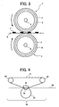
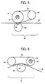
- Figs. 3 to 6 are outlined views illustrating the main portion of the fixing device of the present invention.
- One of the fixing method in the image forming method of the present invention is to fix a toner image by passing a support bearing a toner image between two fixing members upon application of heat. Rollers, films, etc. are used as the member.
- Fig. 3 shows a fixing device using a roller.
- numeral 1 denotes a fixing roller
- numeral 2 denotes a pressure roller respectively.
- the fixing roller is formed by a metallic cylinder 3 made of a heat conductive material such as aluminium, iron, stainless or brass coated with an offset-prevention layer 4 including RTV, silicone rubber, tetrafluoroethylene-perfluoroalkylvinylether (PFA), polytetrafluoroethylene (PTFE), etc.
- PFA tetrafluoroethylene-perfluoroalkylvinylether
- PTFE polytetrafluoroethylene
- a heating lamp 5 is arranged inside the metallic cylinder 3, inside the metallic cylinder 3, a heating lamp 5 is arranged.
- a metallic cylinder 6 of the pressure roller 2 is made of the same material as that of the metallic cylinder 3 of the fixing roller 1 in many cases, and the surface of the cylinder 6 is coated with an offset-prevention layer 7 including PFA, PTFE, etc.
- a heating lamp 8 is optionally arranged inside the pressure roller 2.
- the fixing roller 1 and the pressure roller 2 are pressed each other by springs (not shown) at both sides and rotate.
- a support S (a transfer sheet such as a paper) with a toner image T passes between the fixing roller 1 and the pressure roller 2 to fix an image on the support.
- the fixing device of the present invention has a fixing roller including a metallic cylinder having a thickness of not greater than 0.7 mm, which improves the properties of rising the temperature of the fixing roller and can rise the temperature up to the predetermined temperature in quite a short time.
- the thickness of the metallic cylinder is preferably from 0.2 to 0.5 mm, though depending on the strength and the heat conductivity of the material used for the cylinder.
- a load between the fixing roller and the pressure roller (facing pressure) is preferably not greater than 1.5 x 10 5 Pa.
- the facing pressure is determined by dividing the load on the both sides of the rollers by the roller contact area.
- the roller contact area is determined as follows:
- the facing pressure of the rollers is effectively used for fixing a toner image.
- the load is not grater than 1.5 x 10 5 Pa, and preferably from 0.4 to 1.0 x 10 5 Pa.
- the above-mentioned device has both sufficient low-temperature fixability and durability even in a short standby time.
- the reason why the above-mentioned toner has sufficient fixability is the agglutinability of the toner besides an embedding (anchor) effect of the toner on a paper in the device of the present invention having the quite small facing pressure . Therefore, it is found that a toner having a small particle diameter has an advantage in the present invention.
- Fig. 4 is an embodiment of a fixing portion having one heater.
- the heater is a belt-shaped heater 31, and is pressed against a fixed heating element 32 by a pressure member 33.
- a tension is applied to the heater 31 by a rotatable tensioner 34.
- a recording medium 28 is transferred by a transferer (not shown) to a contact heating area 35 formed by the heater 31 and the pressure member 33 in the fixing portion 30, and then an image is fixed by a heat pressing. At this point, a toner image is formed on the side of the recording medium 28 facing the heater 31.
- Fig. 5 is an embodiment of a fixing portion having two heaters, in which the contact heating area is mainly formed by a pressure of the pressure member.
- the heater is formed by a hollow roller-shaped heater 41 and a belt-shaped heater 42, and a heating element 43 is arranged inside the heater 41.
- the heater 42 is pressed against the heater 41 by a pressure member 44.
- a tension is applied to the heater 42 by a rotatable roller-shaped tensioner 45.
- a recording medium 28 is transferred by a transferer (not shown) to a contact heating area 46 formed by the heater 42 and the pressure member 44 in the fixing portion 40, and then an image is fixed by a heat pressing. At this point, a toner image is formed on the side of the recording medium 28 facing the heater 42.
- Fig. 6 is an embodiment of a fixing portion having two heaters, in which the contact heating area is formed by a tension of a belt-shaped heater.
- the heater is formed by a hollow roller-shaped heater 51 and a belt-shaped heater 52, and a heating element 53 is arranged inside the heater 51.
- a tension is applied to the heater 52 by a rotatable roller-shaped tensioner 54, and the heater 52 is pressed by a pressure member 55 to form a contact heating area 56.
- a recording medium 28 is transferred by a transferer (not shown) to the contact heating area 56 formed by the heater 52 and the pressure member 55 in the fixing portion 50, and then an image is fixed by a heat pressing. At this point, a toner image is formed on the side of the recording medium 28 facing the heater 52.
- a release-oil applicator may be arranged in these fixing devices for the purpose of preventing or assisting to prevent a hot offset.
- Fig. 7 is a schematic view illustrating a main part of an embodiment of the image forming apparatus 100 useful for the image forming method of the present invention.
- a toner container 1 is horizontally and detachably set in a toner supplying device 20 of an image forming apparatus 100.
- the toner supplying device 20 includes a toner container supporting member 22 which supports a toner container 1 such that the opening 2 of the toner container 1 leads to a toner supplying portion 26 in a developing device 40 of the image forming apparatus 100.
- the toner supplying device 20 includes a toner container rotating member 24 which rotates the toner container 1 such that the container 1 rotates around the center axis thereof. A toner t is discharged from the opening 2 toward the toner supplying portion 26.
- a layer of a developer including the toner t is formed on a developing roller 42.
- a photoreceptor 30 i.e., an image bearing member
- an imagewise light irradiating device 34 irradiates the charged photoreceptor with light to form an electrostatic latent image on the photoreceptor 30.
- the latent image is developed with the developer layer to form a toner image on the photoreceptor 30.
- the toner image is transferred to a receiving paper P using a transfer device 50.
- the photoreceptor 30 is cleaned with a cleaner 60.
- the toner image on the receiving paper P is fixed by a belt fixing device (not shown). Thus, a document is produced.
- the developer may be a one component developer (i.e., a toner) or a two-component developer which includes a toner and a carrier.
- the container 1 may includes only a toner or a two-component developer.
- the present invention provides an image forming apparatus, in which a time between the time when the apparatus is turned on and the time when the apparatus is ready to produce an image (a standby time) is not longer than 15, preferably 10 seconds.
- the apparatus has a total electric consumption of not greater than 1.5 KW when working, and not greater than 30W when not working.
- the apparatus can have enough low-temperature fixability and reduce the total electric consumption as well.
- an image forming method includes at least a cleaning process, in which an elastic rubber blade contacting the photoreceptor in the direction thereof cleans the residual toner thereon after a toner image developed thereon is transferred on a recording medium because a paper dust and a filming toner can be effectively removed.
- binder resin for use in the toner of the present invention include styrene and its substitute polymers such as polystyrene, poly-p-chlorostyrene and polyvinyltoluene; styrene copolymers such as styrene-p-chlorostyrene copolymers, styrene-propylene copolymers, styrene-vinyltoluene copolymers, styrene-vinylnaphthalene copolymers, styrene-methylacrylate copolymers, styrene-ethylacrylate copolymers, styrene-butylacrylate copolymers, styrene-octylacrylate copolymers, styrene-ethylmethacrylate copolymers, styrene-butylmethacrylate copolymers,
- release agents can be used as the release agent of the present invention.
- free-fatty- acid type carnauba waxes, montan waxes and oxidized rice waxes can be used alone or in combination.
- the carnauba wax has a microcrystal and an acid value of not greater than 5, and that the particle diameter is not greater than 1 ⁇ m when dispersed in a toner binder.
- the montan wax is typically a wax refined from a mineral substance, and preferably has a microcrystal as the carnauba wax does and an acid value of from 5 to 14.
- the oxidized rice wax is a rice-bran wax oxidized in the air, and preferably has an acid value of from 10 to 30.
- any other known release agents such as solid-silicone varnish, higher-fatty-acid higher alcohol, montan ester waxes, low-molecular-weight polypropylene waxes and the like can be used in combination.
- the content of the release agent is from 1 to 20 parts by weight, preferably from 3 to 10 parts by weight per 100 parts by weight of the resin included in the toner.
- the volume-average particle diameter of the release agent before dispersed in the toner binder is preferably from 10 to 800 ⁇ m. When the particle diameter is less than 10 ⁇ m, the dispersion diameter in the toner binder is small and the releasability is not sufficient, resulting in occurrence of offset.
- the particle diameter is greater than 800 ⁇ m
- the dispersion diameter in the toner binder is large and the precipitaion of the release agent on the surface of the toner becomes large, resulting in occurrence of the fluidity deterioration and adherence to a developing device of the toner.
- a laser diffraction/scattering particle size distribution instrument model No. LA-920 from Horiba, Ltd. is used to measure the particle diameter.
- the magnetic material for use in the present invention include iron oxide such as magnetite, hematite and ferrite; metals such as iron, cobalt and nickel; or metal alloys such as the metals with aluminium, cobalt, copper, lead, magnesium, tin, zinc, stibium, beryllium, bismuth, cadmium, calcium, manganese, selenium, titanium, tungsten and vanadium; and the mixture of these materials.
- iron oxide such as magnetite, hematite and ferrite
- metals such as iron, cobalt and nickel
- metal alloys such as the metals with aluminium, cobalt, copper, lead, magnesium, tin, zinc, stibium, beryllium, bismuth, cadmium, calcium, manganese, selenium, titanium, tungsten and vanadium; and the mixture of these materials.
- the magnetic material has an average particle diameter of from 0.1 to 1 ⁇ m, preferably from 0.2 to 0.4 ⁇ m.
- the content of the magnetic material included in the toner is preferably from 20 to 200 parts by weight, more preferably from 30 to 100 parts by weight per 100 parts by weight of the resin included in the toner.
- any known dyes and pigments such as carbon black, lamp black, iron black, aniline blue, Phthalocyanine Blue, Phthalocyanine Green, Hansa Yellow G, Rhodamine 6C Lake, chalco Oil Blue, chrome yellow, quinacridone, Benzidine Yellow, Rose Bengal and triallylmethane dyes can be used alone or in combination.
- the dyes and pigments can be used as a black toner as well as a full-color toner.
- the content of the colorant included in the toner is from 1 to 30 % by weight, preferably from 3 to 20 % by weight per 100 % of the resin included in the toner.
- the toner of the present invention may optionally include a charge controller, a fluidity improver, etc.
- any known charge controllers such as nigrosin dyes, metal complex dyes and quaternary ammonium salt can be used alone or in combination.
- the negative charge controller includes metallic salts of mono azo dyes, salicylic acid, metal complex of dicarboxylic acid, etc.
- the content of the charge controller is from 0.1 to 10 parts by weight, preferably from 1 to 5 parts by weight per 100 parts by weight of the resin included in the toner.
- any known fluidity improvers such as silicon oxide, titanium oxide, silicon carbide, aluminium oxide, barium titanate, etc. can be used alone or in combination.
- the content of the fluidity improver is from 0.1 to 5 parts by weight, preferably from 0.5 to 2 parts by weight per 100 parts by weight of the toner.
- a carrier for use in a two-component developer including the toner of the present invention all known carriers such as magnetic powders like iron powder, ferrite powder, nickel powder and the like powders; glass beads and the like; and these materials coated with a resin, etc. can be used.
- the resin powders which can be coated on the carrier of the present invention include styrene-acryl copolymers, silicone resins, maleic acid resins, fluorocarbon resins, polyester resins, epoxy resins, etc. It is preferable to use a styrene-acryl copolymer having styrene of from 30 to 90 % by weight. When the styrene is less than 30 %, the developing properties deteriorate. When the styrene is greater than 90 % by weight, the coated layer becomes hard and easy to peel off, resulting in short-life of the carrier.
- the coating on the carrier of the present invention may include an adhesion imparting agent, a hardener, a lubricant, a conductive material, a charge controlling agent, etc. besides the above-mentioned resins.
- a battery electrolyte is an aqueos solution including 1 % of NaCl using a primary natrium chloride. The measurement is performed as follows:
- the circle-equivalent particle diameter and the number distribution can be measured by the flow-type particle image analyzer model No. FPIA-2100 from SYSMEX Co., Ltd.
- the outline of the apparatus and the measurement is disclosed in Japanese Laid-Open Publication No. 8-136439. The measurement is performed as follows:
- the GPC of the present invention is measured as follows:
- the samples for making the calibration curve for example, the samples having a molecular weight of 6 x 10 2 , 2.1 x 10 3 , 4 x 10 3 , 1.75 x 10 4 , 5.1 x 10 4 , 1.1 x 10 5 , 3.9 x 10 5 , 8.6 x 10 5 , 2 x 10 6 and 48 x 10 6 from Pressure Chemical Co. or Tosoh Corporation are used. It is preferable to use at least 10 kinds of the standard polystyrene samples. In addition, an RI (refraction index) detector is used as the detector.
- a manufacturing example of a carrier including a silicone resin in the coated layer for use in the present examples will be explained. This can be manufactured by known methods.
- the coating liquid was coated on 1,000 parts by weight of a spherical ferrite having an average particle diameter of 80 ⁇ m by a fluidized-bed coater to prepare a carrier A.
- the mixture was heated and melted by a roll mill at from 130 to 140 °C for 30 min., and cooled at a room temperature to prepare a mixture A.
- the mixture A was crushed by a hammer mill to have a particle diameter of from 200 to 400 ⁇ m.
- the crushed mixture was pulverized and classified by a pulverizing classifier model No. IDS-2 manufactured by Nippon Pneumatic Mfg. Co., Ltd., which has a pulverizer pulverizing the crushed mixture by crashing the mixture against the crash board by a jet stream as well as a wind classifier classifying the pulverized mixture by centrifugation by forming a rotating airflow in the classifying room.
- a classified toner is prepared.
- the particle-diameter distribution is measured by the Coulter counter and the flow-type particle image analyzer.
- the desired particle-diameter distribution can be provided by changing such as the amount of the crushed mixture supplied to the pulverizer; the air pressure and the airflow for pulverizing; the shape of the crash member for crashing; the air inflow location and direction in the classifier; and the pressure of the exhaust blower.
- Polyester resin (The weight average 60 molecular weight is 7,000, the melting point is 110 °C and the acid value is mg KOH/g) Polyester resin (The weight average 40 molecular weight is 80,000, the melting point is 143 °C and the acid value is 20 mg KOH/g) Carnauba wax (The melting point is 82 °C and 3 the volume-average particle diameter is 490 ⁇ m.) Carbon black (tradenamed as # 44 8 manufactured by Mitsubishi Kasei Corporation) A metal-containing azo compound 3
- the molecular-weight distribution of the toner 3 had a main peak at 4,000 and the half width of the peak was 12,000.
- the procedures for preparation of the toner 3 and the developer 3 were repeated except for additionally including 50 parts by weight of fine particles of magnetite having a particle diameter of 0.25 ⁇ m into the materials to prepare a toner 4 having a particle-diameter distribution described in Table 1 and a developer 4.
- the molecular-weight distribution of the toner 4 had a main peak at 4,000 and the half width of the peak was 12,000.
- a copy test was performed using the following apparatus and copy paper.
- the fixing temperature was changed for each developer to produce a copy image having an image density of 0.8 which was measured by a Macbeth densitometer. Each copy image was scraped by a clock meter having a cloth of cotton No. 3 of JIS-L-0803 standard for 10 times. Then, the density of the toner transferred to the cloth was measured by the Macbeth densitometer. The temperature to achieve the density of not greater than 0.4 was determined as the minimum fixing temperature.
- the minimum fixing temperature of the current toner (Imagio toner type 12 having a volume-average particle diameter of 9.60 ⁇ m and 15 % by number of the particles having a particle diameter of not greater than 5 ⁇ m) was 190 °C. Good o ⁇ : less than 160 °C ⁇ : 160 to 170 °C ⁇ : 170 to 180 °C ⁇ : 180 to 190 °C ⁇ : greater than 190 °C Poor
- each 100,000 copies of a laterally-set A4 chart (image pattern A) in which a black and a white solid image are repeatedly printed at an interval of 1 cm were produced by the copier model No. MF-4550 manufactured by Ricoh Company, Ltd. such that the longitudinal direction of the black and white solid images is perpendicular to the direction of the rotating direction of the developing sleeve.
- the copier had a cleaning blade and a charging roller which contact the photoreceptor. Then, an image produced afterwards by each developer was evaluated by the following methods.
- a black solid image having an area of 1 cm x 1 cm was produced in a lateral A4 sheet by each developer.
- the density of the center and the four corners of each image was measured by the Macbeth densitometer to determine the average density of the five places.
- An A3 copy of a repeated black and white image (halftone) was produced at 2 dots x 2 dots (600 dpi) by each developer. Each image was graded into the following 5 grades. As for a poor image, a toner image was developed on the sleeve in a reverse pattern, and irregularity of the image density appeared particularly when a halftone image was produced. Good o ⁇ : Quite good ⁇ : Good ⁇ : Normal ⁇ : Poor ⁇ : Quite poor Poor
- a dot line image was produced by each developer, and each image was graded into the following 5 grades.
- Good o ⁇ Quite good ⁇ : Good ⁇ : Normal ⁇ : Poor ⁇ : Quite poor Poor
- the toner density of the non-image portion of each initial image and the image after 100,000 copies were produced was graded into the following 5 grades.
- Good o ⁇ Quite good ⁇ : Good ⁇ : Normal ⁇ : Poor ⁇ : Quite poor Poor
- Example 1 Developer 1 ⁇ ⁇ ⁇ ⁇ ⁇ ⁇ Example 2 Developer 2 ⁇ ⁇ o ⁇ ⁇ ⁇ Example 3 Developer 3 o ⁇ ⁇ ⁇ ⁇ ⁇ Example 4 Developer 4 o ⁇ ⁇ ⁇ ⁇ ⁇ o ⁇ Comparative example 1 Developer 5 ⁇ ⁇ ⁇ ⁇ ⁇ Comparative example 2 Developer 6 ⁇ ⁇ ⁇ ⁇ Comparative example 3 Developer 7 ⁇ ⁇ ⁇ ⁇ ⁇ ⁇ ⁇ ⁇
Landscapes
- Physics & Mathematics (AREA)
- General Physics & Mathematics (AREA)
- Spectroscopy & Molecular Physics (AREA)
- Engineering & Computer Science (AREA)
- Microelectronics & Electronic Packaging (AREA)
- Developing Agents For Electrophotography (AREA)
- Fixing For Electrophotography (AREA)
- Dry Development In Electrophotography (AREA)
- Cleaning In Electrography (AREA)
Abstract
Description
| Liquid solution of a silicone resin | 100 |
| (tradenamed as SR2411 manufactured by | |
| Toray Silicone Industries, Inc.) | |
| Carbon black (tradenamed as # 44 | 4 |
| manufactured by Mitsubishi Kasei Corporation) | |
| | 100 |
| Styrenemethylacrylate (The | 100 |
| molecular weight is 440,000 and the melting | |
| point is 127 °C. ) | |
| Carnauba wax (The melting point is 82 °C and | 3 |
| the volume-average particle diameter is 490 | |
| µm.) | |
| Carbon black (tradenamed as # 44 | 8 |
| manufactured by Mitsubishi Kasei Corporation) | |
| A metal-containing | 3 |
| Polyester resin (The | 60 |
| molecular weight is 7,000, the melting | |
| point is 110 °C and the acid value is | |
| mg KOH/g) | |
| Polyester resin (The | 40 |
| molecular weight is 80,000, the melting | |
| point is 143 °C and the acid value is | |
| 20 mg KOH/g) | |
| Carnauba wax (The melting point is 82 °C and | 3 |
| the volume-average particle diameter is 490 µm.) | |
| Carbon black (tradenamed as # 44 | 8 |
| manufactured by Mitsubishi Kasei Corporation) | |
| A metal-containing | 3 |
| Example 1 | | 6.78 | 62.6 | 23 |
| Example 2 | | 6.85 | 60.2 | 14.8 |
| Example 3 | | 6.79 | 63.5 | 20.5 |
| Example 4 | | 6.78 | 62.6 | 23 |
| Comparative example 1 | | 6.82 | 55.5 | 13.8 |
| Comparative example 2 | | 6.62 | 64.8 | 33.9 |
| Comparative example 3 | Toner 7 | 4.4 | 74.5 | 23.2 |
Good
o ○ : less than 160 °C
○ : 160 to 170 °C
□ : 170 to 180 °C
Δ : 180 to 190 °C
× : greater than 190 °C
Poor
Good
o ○ : not less than 1.4
○ : 1.3 to 1.4
□ : 1.2 to 1.3
Δ : 1.1 to 1.2
× : not greater than 1.1
Poor
Good
o ○ : Quite good
○ : Good
□ : Normal
Δ : Poor
× : Quite poor
Poor
Good
o ○ : Quite good
○ : Good
□ : Normal
Δ : Poor
× : Quite poor
Poor
Good
o ○ : Quite good
○ : Good
□ : Normal
Δ : Poor
× : Quite poor
Poor
| Example 1 | | ○ | ○ | ○ | ○ | ○ |
| Example 2 | | ○ | ○ | o ○ | ○ | ○ |
| Example 3 | Developer 3 | o ○ | ○ | ○ | ○ | ○ |
| Example 4 | Developer 4 | o ○ | ○ | ○ | ○ | o ○ |
| Comparative example 1 | | □ | ○ | ○ | □ | ○ |
| Comparative example 2 | | ○ | Δ | × | ○ | ○ |
| Comparative example 3 | Developer 7 | □ | Δ | Δ | ○ | ○ |
Claims (20)
- An image forming toner comprising:wherein a volume-average particle diameter of the toner measured by a Coulter counter is from 5 to 8 µm; the content of the toner having a volume-average particle diameter of not greater than 5 µm is 60 to 75 % by number; and the content of the toner having a number-basis circle-equivalent particle diameter of from 0.6 to 3 µm measured by a flow-type particle image analyzer is not greater than 25 %.a binder resin;a colorant; anda release agent,
- The image forming toner of Claim 1, wherein the content of the toner having a number-basis circle-equivalent particle diameter of from 0.6 to 3 µm measured by a flow-type particle image analyzer is not greater than 15 %.
- The image forming toner of Claim 1 or 2, wherein the toner has a peak at a molecular weight of at least between 1,000 and 10,000 and a half width of the peak of not longer than 15,000 when the molecular-weight distribution of tetrahydrofuran-soluble components of the toner is determined by Gel Permeation Chromatography (GPC).
- The image forming toner of any one of Claims 1 to 3, wherein the binder resin is a polyester resin.
- The image forming toner of any one of Claims 1 to 4, wherein the volume-average particle diameter of the release agent before dispersed in the toner binder is from 10 to 800 µm.
- The image forming toner of any one of Claims 1 to 5, further comprising a magnetic material.
- An image forming apparatus comprising:wherein a time between the time when the image forming apparatus is turned on and the time when the image forming apparatus produces an image (a standby time) is not longer than 15 seconds, and a total electric consumption of the apparatus is not greater than 1.5 KW when working, and not greater than 30W when not working, andan image bearing member configured to bear an electrostatic latent image;an image developer configured to develop the latent image with a developer comprising a carrier and a toner to form a toner image on the image bearing member;an image transferer configured to transfer the toner image on a transfer sheet; anda fixer configured to fix the toner image on the transfer sheet,
wherein the toner is the image forming toner of any one of Claims 1 to 6. - The image forming apparatus of Claim 7, wherein a time between the time when the image forming apparatus is turned on and the time when the image forming apparatus produces an image (a standby time) is not longer than 10 seconds.
- The image forming apparatus of Claim 7, which can produce not less than 30 sheets of A4 size image a minute.
- An image forming method comprising:wherein the thickness of the fixing member contacting the face of the transfer sheet bearing the toner image is not greater than 0.7 mm, and a facing pressure applied to the two fixing members is not greater than 1.5 x 10⁵ Pa (a load on the fixing member/contact area), andtransferring a toner image on a transfer sheet; andfixing the toner image upon application heat on the transfer sheet by passing the transfer sheet between two fixing members,
wherein the toner is the image forming toner of any one of Claims 1 to 6. - An image forming method comprising:wherein the heating member has a shape of belt with an edge or without an edge, andtransferring a toner image on a transfer sheet;heating a heating member by a fixed heating element; andpressing the transfer sheet bearing the toner image against the heating member to fix the image on the transfer sheet,
wherein the toner is the image forming toner of Claim 1. - An image forming method comprising:wherein the toner is the image forming toner of any one of Claims 1 to 6.charging an image bearer by a charger contacting the image bearer;transferring a toner image developed on the image bearer to a transfer sheet; andcleaning the residual toner on the image bearer by an elastic rubber blade contacting the image bearer,
- An image forming apparatus comprising:wherein the thickness of the fixing member contacting the face of the transfer sheet bearing the toner image is not greater than 0.7 mm, and a facing pressure applied to the two fixing members is not greater than 1.5 x 10⁵ Pa (a load on the fixing member/contact area), anda transferer configured to transfer a toner image on a transfer sheet;a fixer comprising two fixing members configured to fix the toner image on the transfer sheet upon application of heat by passing the transfer sheet therebetween,
wherein the toner is the image forming toner of any one of Claims 1 to 6. - An image forming apparatus comprising:wherein the heating member has a shape of belt with an edge or without an edge, anda transferer configured to transfer a toner image on a transfer sheet;a fixer comprising a heating element configured to heat a heating member; anda pressure member configured to press the transfer sheet against the heating member to fix the image on the transfer sheet,
wherein the toner is the image forming toner of any one of Claims 1 to 6. - An image forming apparatus comprising:wherein the toner is the image forming toner of any one of Claims 1 to 6.a charger configured to charge an image bearer contacting the image bearer;a transferer configured to transfer a toner image developed on the image bearer to a transfer sheet; anda cleaner configured to clean the residual toner on the image bearer with an elastic rubber blade contacting the image bearer,
- A two-component image forming developer comprising a carrier and the image forming toner of any one of Claims 1 to 6.
- A toner container containing the image forming toner of any one of Claims 1 to 6.
- A container containing the two-component developer of Claim 16.
- An image forming apparatus comprising the toner container of Claim 17.
- An image forming apparatus comprising the container of Claim 18.
Priority Applications (1)
| Application Number | Priority Date | Filing Date | Title |
|---|---|---|---|
| EP07019428.7A EP1870775B1 (en) | 2000-11-30 | 2001-11-30 | Image forming apparatus |
Applications Claiming Priority (2)
| Application Number | Priority Date | Filing Date | Title |
|---|---|---|---|
| JP2000365581A JP3912649B2 (en) | 2000-11-30 | 2000-11-30 | Image forming toner, image forming method, and image forming apparatus |
| JP2000365581 | 2000-11-30 |
Related Child Applications (1)
| Application Number | Title | Priority Date | Filing Date |
|---|---|---|---|
| EP07019428.7A Division EP1870775B1 (en) | 2000-11-30 | 2001-11-30 | Image forming apparatus |
Publications (3)
| Publication Number | Publication Date |
|---|---|
| EP1211566A2 true EP1211566A2 (en) | 2002-06-05 |
| EP1211566A3 EP1211566A3 (en) | 2003-08-06 |
| EP1211566B1 EP1211566B1 (en) | 2008-01-02 |
Family
ID=18836328
Family Applications (2)
| Application Number | Title | Priority Date | Filing Date |
|---|---|---|---|
| EP01310082A Expired - Lifetime EP1211566B1 (en) | 2000-11-30 | 2001-11-30 | Image forming toner, and image forming method and image forming apparatus using the toner |
| EP07019428.7A Expired - Lifetime EP1870775B1 (en) | 2000-11-30 | 2001-11-30 | Image forming apparatus |
Family Applications After (1)
| Application Number | Title | Priority Date | Filing Date |
|---|---|---|---|
| EP07019428.7A Expired - Lifetime EP1870775B1 (en) | 2000-11-30 | 2001-11-30 | Image forming apparatus |
Country Status (4)
| Country | Link |
|---|---|
| US (1) | US6699632B2 (en) |
| EP (2) | EP1211566B1 (en) |
| JP (1) | JP3912649B2 (en) |
| DE (1) | DE60132161T2 (en) |
Cited By (1)
| Publication number | Priority date | Publication date | Assignee | Title |
|---|---|---|---|---|
| EP3432074A4 (en) * | 2016-03-15 | 2019-01-23 | Ricoh Company, Ltd. | Toner, toner-housing unit, and image-forming apparatus |
Families Citing this family (39)
| Publication number | Priority date | Publication date | Assignee | Title |
|---|---|---|---|---|
| JP4107817B2 (en) * | 2000-09-29 | 2008-06-25 | 株式会社リコー | Image forming toner, image forming method, and image forming apparatus |
| US7157201B2 (en) * | 2002-06-28 | 2007-01-02 | Ricoh Company, Ltd. | Toner for developing latent electrostatic image, container having the same, developer using the same, process for developing using the same, image-forming process using the same, image-forming apparatus using the same, and image-forming process cartridge using the same |
| JP4079257B2 (en) * | 2002-10-01 | 2008-04-23 | 株式会社リコー | Toner for electrostatic image development |
| JP4056377B2 (en) * | 2002-12-16 | 2008-03-05 | 株式会社リコー | Toner for electrostatic image development |
| US7177555B2 (en) | 2003-01-15 | 2007-02-13 | Ricoh Company, Ltd. | Image forming process and image forming apparatus |
| US7103301B2 (en) * | 2003-02-18 | 2006-09-05 | Ricoh Company, Ltd. | Image forming apparatus using a contact or a proximity type of charging system including a protection substance on a moveable body to be charged |
| JP3905048B2 (en) * | 2003-03-17 | 2007-04-18 | 株式会社リコー | Toner for developing electrostatic image, process cartridge, fixing method, image forming method, and image forming apparatus |
| US7306887B2 (en) * | 2003-03-19 | 2007-12-11 | Ricoh Company, Ltd. | Toner and developer for electrostatic development, production thereof, image forming process and apparatus using the same |
| JP4069007B2 (en) * | 2003-03-19 | 2008-03-26 | 株式会社リコー | Image forming toner |
| US7163775B2 (en) * | 2003-03-19 | 2007-01-16 | Ricoh Company Limited | Toner for developing electrostatic image, method for manufacturing the toner, developer including the toner, container containing the toner, and color image forming method using the toner |
| JP4030907B2 (en) * | 2003-03-19 | 2008-01-09 | 株式会社リコー | Toner for electrostatic image development |
| US7125638B2 (en) | 2003-03-24 | 2006-10-24 | Ricoh Company, Ltd. | Image forming method and image forming apparatus for same |
| JP4037329B2 (en) * | 2003-06-25 | 2008-01-23 | 株式会社リコー | Toner for developing electrostatic image, developer, image forming method, image forming apparatus, and process cartridge |
| US7162187B2 (en) * | 2003-06-30 | 2007-01-09 | Ricoh Company, Ltd. | Image forming apparatus and image forming method |
| JP4386339B2 (en) * | 2003-10-10 | 2009-12-16 | 株式会社リコー | Image forming apparatus and image forming method |
| US7642032B2 (en) * | 2003-10-22 | 2010-01-05 | Ricoh Company, Limited | Toner, developer, image forming apparatus and image forming method |
| JP4335055B2 (en) * | 2003-12-09 | 2009-09-30 | 株式会社リコー | Image forming method |
| US7315722B2 (en) * | 2003-12-25 | 2008-01-01 | Ricoh Company, Ltd. | Image forming apparatus and image forming method |
| JP4319553B2 (en) * | 2004-01-08 | 2009-08-26 | 株式会社リコー | Electrophotographic photoreceptor, method for producing electrophotographic photoreceptor, electrophotographic apparatus, process cartridge |
| JP4451256B2 (en) | 2004-09-13 | 2010-04-14 | 株式会社リコー | Image forming apparatus |
| US20060240350A1 (en) * | 2005-04-22 | 2006-10-26 | Hyo Shu | Developer, and image forming apparatus and process cartridge using the developer |
| EP1744222B1 (en) * | 2005-07-15 | 2011-02-02 | Ricoh Company, Ltd. | Toner, developer, image forming method, and toner container |
| JP4749925B2 (en) * | 2006-04-21 | 2011-08-17 | 株式会社リコー | Image forming apparatus, image forming method, and process cartridge |
| US8034526B2 (en) * | 2006-09-07 | 2011-10-11 | Ricoh Company Limited | Method for manufacturing toner and toner |
| JP2008070570A (en) | 2006-09-13 | 2008-03-27 | Ricoh Co Ltd | Developing device, image forming apparatus |
| JP5084034B2 (en) * | 2007-03-16 | 2012-11-28 | 株式会社リコー | Image forming method |
| JP4866278B2 (en) | 2007-03-19 | 2012-02-01 | 株式会社リコー | Toner, developer, toner container, process cartridge, image forming method, and image forming apparatus |
| US20090104804A1 (en) * | 2007-10-23 | 2009-04-23 | Jeff Lin | Led metal strip flexible interconnection |
| US7901861B2 (en) * | 2007-12-04 | 2011-03-08 | Ricoh Company Limited | Electrophotographic image forming method |
| US8012659B2 (en) * | 2007-12-14 | 2011-09-06 | Ricoh Company Limited | Image forming apparatus, toner, and process cartridge |
| JP5708971B2 (en) * | 2010-03-10 | 2015-04-30 | 株式会社リコー | Image forming apparatus |
| JP2012022264A (en) | 2010-07-16 | 2012-02-02 | Ricoh Co Ltd | Image forming apparatus and image forming method |
| EP2439592B1 (en) * | 2010-10-05 | 2018-08-15 | Toshiba TEC Kabushiki Kaisha | electrophotographic toner and method for producing the same |
| US9933721B2 (en) | 2010-10-05 | 2018-04-03 | Toshiba Tec Kabushiki Kaisha | Electrophotographic toner and method for producing the same |
| JP5724449B2 (en) | 2011-02-23 | 2015-05-27 | 株式会社リコー | Image forming apparatus and image forming method |
| JP2012177847A (en) * | 2011-02-28 | 2012-09-13 | Ricoh Co Ltd | Image forming apparatus |
| JP6520501B2 (en) * | 2014-07-24 | 2019-05-29 | 株式会社リコー | Toner, image forming apparatus, image forming method, and process cartridge |
| US10324388B2 (en) | 2016-03-18 | 2019-06-18 | Ricoh Company, Ltd. | Toner, toner stored unit, image forming apparatus, and image forming method |
| JP2023105448A (en) | 2022-01-19 | 2023-07-31 | 株式会社リコー | image forming device |
Family Cites Families (48)
| Publication number | Priority date | Publication date | Assignee | Title |
|---|---|---|---|---|
| JPH0654396B2 (en) | 1985-08-29 | 1994-07-20 | 株式会社リコー | Toner for electrostatic image development |
| US4762763A (en) | 1985-12-19 | 1988-08-09 | Ricoh Co., Ltd. | Toner for developing electrostatic latent image |
| US4908290A (en) | 1986-11-17 | 1990-03-13 | Ricoh Company, Ltd. | Toner for developing latent electrostatic images |
| JP2750853B2 (en) | 1986-11-20 | 1998-05-13 | 株式会社リコー | Toner for developing electrostatic latent images |
| JPS6472169A (en) | 1987-09-11 | 1989-03-17 | Ricoh Kk | Toner for color electrophotography |
| JPH0760273B2 (en) | 1987-10-26 | 1995-06-28 | キヤノン株式会社 | Magnetic developer |
| JP2763318B2 (en) * | 1988-02-24 | 1998-06-11 | キヤノン株式会社 | Non-magnetic toner and image forming method |
| US4980258A (en) | 1988-11-17 | 1990-12-25 | Ricoh Company, Ltd. | Dry type developer for electrophotography |
| JP2942588B2 (en) | 1989-11-02 | 1999-08-30 | 株式会社リコー | Negatively chargeable toner for developing electrostatic images |
| JP3037711B2 (en) | 1990-03-22 | 2000-05-08 | 株式会社リコー | Digital full-color electrophotographic method |
| JPH04271359A (en) | 1991-02-27 | 1992-09-28 | Ricoh Co Ltd | Developer for dry processing |
| JP3421751B2 (en) | 1991-12-06 | 2003-06-30 | 株式会社リコー | Toner for developing electrostatic images |
| US5368972A (en) | 1992-02-15 | 1994-11-29 | Ricoh Company, Ltd. | Method of preparing composite particles comprising adhering wax particles to the surface of resin particles |
| JP3156881B2 (en) | 1992-10-19 | 2001-04-16 | 株式会社リコー | Electrostatic toner |
| US5255303A (en) | 1992-11-17 | 1993-10-19 | Duke University | Multi-purpose emergency room trauma board |
| US5403690A (en) | 1993-03-31 | 1995-04-04 | Ricoh Company, Ltd. | Developer for developing latent electrostatic images |
| JP3313895B2 (en) | 1993-07-12 | 2002-08-12 | 株式会社リコー | Dry type electrophotographic toner |
| JP3223689B2 (en) * | 1994-03-04 | 2001-10-29 | ミノルタ株式会社 | Toner for developing electrostatic latent images |
| JP3174987B2 (en) * | 1994-04-22 | 2001-06-11 | キヤノン株式会社 | Two-component developer and image forming method |
| DE19534384B4 (en) | 1994-09-16 | 2015-08-20 | Ricoh Co., Ltd. | Color dry toner for electrophotography and production thereof |
| US6004715A (en) | 1995-06-26 | 1999-12-21 | Ricoh Company, Ltd. | Toner for developing electrostatic images |
| JPH09106105A (en) | 1995-08-08 | 1997-04-22 | Ricoh Co Ltd | Color toner |
| US5912100A (en) | 1996-01-31 | 1999-06-15 | Ricoh Company, Ltd. | Toner for developing electrostatic images |
| US5882832A (en) | 1996-04-30 | 1999-03-16 | Ricoh Company, Ltd. | One component developer developing method and dry toner therefor |
| US5948582A (en) * | 1997-04-02 | 1999-09-07 | Canon Kabushiki Kaisha | Toner for developing electrostatic image, image forming method and developing apparatus unit |
| EP0869399B1 (en) | 1997-04-04 | 2001-08-29 | Canon Kabushiki Kaisha | Toner for forming an image, image forming method and heat-fixing method |
| JPH1184719A (en) | 1997-07-10 | 1999-03-30 | Ricoh Co Ltd | Dry electrophotographic toner |
| US6010814A (en) | 1997-10-27 | 2000-01-04 | Ricoh Company, Ltd. | Electrophotographic toner composition and image formation method using the composition |
| GB2336442B (en) | 1998-04-17 | 2000-09-06 | Ricoh Kk | Multi-color toner set and method of forming multi-color images, using the multi-color toner set |
| US6228550B1 (en) * | 1998-06-16 | 2001-05-08 | Ricoh Company, Ltd. | Two-component developer |
| US6074795A (en) | 1998-07-01 | 2000-06-13 | Ricoh Company, Ltd. | Toner for developing electrostatic latent image |
| US6183926B1 (en) | 1998-10-26 | 2001-02-06 | Ricoh Company, Ltd. | Toner and two-component developer for electrophotographic process and image formation method and image formation apparatus using the toner |
| US6103441A (en) | 1998-11-12 | 2000-08-15 | Ricoh Company, Ltd. | Color toner for electrophotography |
| US6303258B1 (en) | 1999-01-29 | 2001-10-16 | Ricoh Company, Ltd. | Electrophotographic toner and image forming method using the toner |
| JP2000330324A (en) * | 1999-05-18 | 2000-11-30 | Canon Inc | Image forming method |
| JP4315263B2 (en) | 1999-05-28 | 2009-08-19 | 株式会社リコー | Two-component developer |
| JP3767846B2 (en) | 1999-05-28 | 2006-04-19 | 株式会社リコー | Toner for developing electrostatic image and image forming method |
| FR2795190B1 (en) * | 1999-06-17 | 2002-03-15 | Ricoh Kk | DEVELOPER, DEVELOPER CONTAINER, AND IMAGE FORMING METHOD AND APPARATUS |
| JP4070387B2 (en) | 1999-06-21 | 2008-04-02 | 株式会社リコー | Developing device and image forming apparatus |
| US6432589B1 (en) | 1999-08-10 | 2002-08-13 | Ricoh Company, Ltd. | Image formation method, electrophotographic toners, and printed matter |
| US6403275B1 (en) | 1999-08-31 | 2002-06-11 | Ricoh Company, Ltd. | Electrophotographic toner, and image forming method and apparatus using the toner |
| JP3942139B2 (en) | 1999-10-20 | 2007-07-11 | 株式会社リコー | Electrophotographic developer |
| US6363229B1 (en) | 1999-11-17 | 2002-03-26 | Ricoh Company, Ltd. | Full-color toner image fixing method and apparatus |
| US6360068B1 (en) | 1999-11-19 | 2002-03-19 | Fujitsu Limited | Electrophotographic image formation process and apparatus |
| US6395443B2 (en) | 1999-11-29 | 2002-05-28 | Ricoh Company, Ltd. | Toner for developing electrostatic image and process of preparing same |
| JP2001242712A (en) | 2000-02-28 | 2001-09-07 | Ricoh Co Ltd | Image forming device |
| JP2002072586A (en) | 2000-08-31 | 2002-03-12 | Ricoh Co Ltd | Image forming device |
| US6505014B2 (en) | 2000-09-29 | 2003-01-07 | Ricoh Company, Ltd. | Image forming apparatus and an image forming process unit |
-
2000
- 2000-11-30 JP JP2000365581A patent/JP3912649B2/en not_active Expired - Lifetime
-
2001
- 2001-11-30 US US09/996,585 patent/US6699632B2/en not_active Expired - Lifetime
- 2001-11-30 EP EP01310082A patent/EP1211566B1/en not_active Expired - Lifetime
- 2001-11-30 EP EP07019428.7A patent/EP1870775B1/en not_active Expired - Lifetime
- 2001-11-30 DE DE60132161T patent/DE60132161T2/en not_active Expired - Lifetime
Cited By (1)
| Publication number | Priority date | Publication date | Assignee | Title |
|---|---|---|---|---|
| EP3432074A4 (en) * | 2016-03-15 | 2019-01-23 | Ricoh Company, Ltd. | Toner, toner-housing unit, and image-forming apparatus |
Also Published As
| Publication number | Publication date |
|---|---|
| EP1870775A2 (en) | 2007-12-26 |
| DE60132161D1 (en) | 2008-02-14 |
| DE60132161T2 (en) | 2008-12-18 |
| EP1211566B1 (en) | 2008-01-02 |
| US6699632B2 (en) | 2004-03-02 |
| JP3912649B2 (en) | 2007-05-09 |
| EP1870775A3 (en) | 2008-05-07 |
| EP1211566A3 (en) | 2003-08-06 |
| US20020102486A1 (en) | 2002-08-01 |
| EP1870775B1 (en) | 2015-11-11 |
| JP2002169322A (en) | 2002-06-14 |
Similar Documents
| Publication | Publication Date | Title |
|---|---|---|
| US6699632B2 (en) | Image forming toner, and image forming method and image forming apparatus using the toner | |
| JP3291618B2 (en) | Image forming toner, image forming method and heat fixing method | |
| AU761654B2 (en) | Magnetic toner | |
| JP4606483B2 (en) | Toner, toner manufacturing method, developer, developing method, and image forming method | |
| HK1045883A1 (en) | Toner for forming image, and image forming method and apparatus using the toner | |
| JP2013156430A (en) | Toner, and image forming apparatus | |
| JP4049688B2 (en) | Toner for electrostatic image development, developer and image forming apparatus | |
| JP2004184719A (en) | Toner and method for producing the same | |
| JP2000147828A (en) | Toner and image forming method | |
| JP4006136B2 (en) | Image forming method | |
| JP4032959B2 (en) | Image forming method and image forming apparatus | |
| JP3854361B2 (en) | Toner for developing electrostatic image and image forming method using the same | |
| JP3093578B2 (en) | Electrophotographic toner | |
| JPH06342224A (en) | Toner particles | |
| US10564565B1 (en) | Electrophotographic image forming apparatus | |
| JP4006283B2 (en) | Toner, image forming method and image forming apparatus | |
| US20200064760A1 (en) | Image forming apparatus | |
| JP2002062684A (en) | Electrostatic image developing toner and image forming method | |
| JP3445030B2 (en) | Toner for developing electrostatic images | |
| JP2002082491A (en) | Toner and image forming method | |
| US10558150B1 (en) | Image forming apparatus | |
| JP2001066936A (en) | Image forming method, image forming device and toner | |
| JP2004109854A (en) | Developer for developing electrostatic charge image and image forming device using the developer | |
| JP3558972B2 (en) | Electrostatic image developing toner and image forming method | |
| JPH1124311A (en) | Electrostatic image developing toner and developing method |
Legal Events
| Date | Code | Title | Description |
|---|---|---|---|
| PUAI | Public reference made under article 153(3) epc to a published international application that has entered the european phase |
Free format text: ORIGINAL CODE: 0009012 |
|
| 17P | Request for examination filed |
Effective date: 20011212 |
|
| AK | Designated contracting states |
Kind code of ref document: A2 Designated state(s): AT BE CH CY DE DK ES FI FR GB GR IE IT LI LU MC NL PT SE TR |
|
| AX | Request for extension of the european patent |
Free format text: AL;LT;LV;MK;RO;SI |
|
| PUAL | Search report despatched |
Free format text: ORIGINAL CODE: 0009013 |
|
| AK | Designated contracting states |
Designated state(s): AT BE CH CY DE DK ES FI FR GB GR IE IT LI LU MC NL PT SE TR |
|
| AX | Request for extension of the european patent |
Extension state: AL LT LV MK RO SI |
|
| AKX | Designation fees paid |
Designated state(s): DE FR GB |
|
| GRAP | Despatch of communication of intention to grant a patent |
Free format text: ORIGINAL CODE: EPIDOSNIGR1 |
|
| RIN1 | Information on inventor provided before grant (corrected) |
Inventor name: NAKAI, HIROSHI Inventor name: SHU, BING Inventor name: MATSUDA, HIROAKI Inventor name: SASAKI, FUMIHIRO Inventor name: HIGUCHI, HIROTO Inventor name: IWAMOTO, YASUAKI Inventor name: KONDO, MAIKO |
|
| GRAS | Grant fee paid |
Free format text: ORIGINAL CODE: EPIDOSNIGR3 |
|
| GRAA | (expected) grant |
Free format text: ORIGINAL CODE: 0009210 |
|
| AK | Designated contracting states |
Kind code of ref document: B1 Designated state(s): DE FR GB |
|
| REG | Reference to a national code |
Ref country code: GB Ref legal event code: FG4D |
|
| REF | Corresponds to: |
Ref document number: 60132161 Country of ref document: DE Date of ref document: 20080214 Kind code of ref document: P |
|
| ET | Fr: translation filed | ||
| PLBE | No opposition filed within time limit |
Free format text: ORIGINAL CODE: 0009261 |
|
| STAA | Information on the status of an ep patent application or granted ep patent |
Free format text: STATUS: NO OPPOSITION FILED WITHIN TIME LIMIT |
|
| 26N | No opposition filed |
Effective date: 20081003 |
|
| REG | Reference to a national code |
Ref country code: FR Ref legal event code: PLFP Year of fee payment: 15 |
|
| REG | Reference to a national code |
Ref country code: FR Ref legal event code: PLFP Year of fee payment: 16 |
|
| REG | Reference to a national code |
Ref country code: FR Ref legal event code: PLFP Year of fee payment: 17 |
|
| PGFP | Annual fee paid to national office [announced via postgrant information from national office to epo] |
Ref country code: FR Payment date: 20201120 Year of fee payment: 20 Ref country code: GB Payment date: 20201120 Year of fee payment: 20 Ref country code: DE Payment date: 20201119 Year of fee payment: 20 |
|
| REG | Reference to a national code |
Ref country code: DE Ref legal event code: R071 Ref document number: 60132161 Country of ref document: DE |
|
| REG | Reference to a national code |
Ref country code: GB Ref legal event code: PE20 Expiry date: 20211129 |
|
| PG25 | Lapsed in a contracting state [announced via postgrant information from national office to epo] |
Ref country code: GB Free format text: LAPSE BECAUSE OF EXPIRATION OF PROTECTION Effective date: 20211129 |