EP1211396A2 - Exhaust gas purifying device for internal combustion engine - Google Patents
Exhaust gas purifying device for internal combustion engine Download PDFInfo
- Publication number
- EP1211396A2 EP1211396A2 EP01128238A EP01128238A EP1211396A2 EP 1211396 A2 EP1211396 A2 EP 1211396A2 EP 01128238 A EP01128238 A EP 01128238A EP 01128238 A EP01128238 A EP 01128238A EP 1211396 A2 EP1211396 A2 EP 1211396A2
- Authority
- EP
- European Patent Office
- Prior art keywords
- fuel
- valve
- emergency shut
- exhaust air
- exhaust
- Prior art date
- Legal status (The legal status is an assumption and is not a legal conclusion. Google has not performed a legal analysis and makes no representation as to the accuracy of the status listed.)
- Granted
Links
Images


Classifications
-
- F—MECHANICAL ENGINEERING; LIGHTING; HEATING; WEAPONS; BLASTING
- F01—MACHINES OR ENGINES IN GENERAL; ENGINE PLANTS IN GENERAL; STEAM ENGINES
- F01N—GAS-FLOW SILENCERS OR EXHAUST APPARATUS FOR MACHINES OR ENGINES IN GENERAL; GAS-FLOW SILENCERS OR EXHAUST APPARATUS FOR INTERNAL COMBUSTION ENGINES
- F01N3/00—Exhaust or silencing apparatus having means for purifying, rendering innocuous, or otherwise treating exhaust
- F01N3/08—Exhaust or silencing apparatus having means for purifying, rendering innocuous, or otherwise treating exhaust for rendering innocuous
- F01N3/0807—Exhaust or silencing apparatus having means for purifying, rendering innocuous, or otherwise treating exhaust for rendering innocuous by using absorbents or adsorbents
- F01N3/0814—Exhaust or silencing apparatus having means for purifying, rendering innocuous, or otherwise treating exhaust for rendering innocuous by using absorbents or adsorbents combined with catalytic converters, e.g. NOx absorption/storage reduction catalysts
-
- F—MECHANICAL ENGINEERING; LIGHTING; HEATING; WEAPONS; BLASTING
- F01—MACHINES OR ENGINES IN GENERAL; ENGINE PLANTS IN GENERAL; STEAM ENGINES
- F01N—GAS-FLOW SILENCERS OR EXHAUST APPARATUS FOR MACHINES OR ENGINES IN GENERAL; GAS-FLOW SILENCERS OR EXHAUST APPARATUS FOR INTERNAL COMBUSTION ENGINES
- F01N9/00—Electrical control of exhaust gas treating apparatus
-
- B—PERFORMING OPERATIONS; TRANSPORTING
- B01—PHYSICAL OR CHEMICAL PROCESSES OR APPARATUS IN GENERAL
- B01D—SEPARATION
- B01D53/00—Separation of gases or vapours; Recovering vapours of volatile solvents from gases; Chemical or biological purification of waste gases, e.g. engine exhaust gases, smoke, fumes, flue gases, aerosols
- B01D53/34—Chemical or biological purification of waste gases
- B01D53/92—Chemical or biological purification of waste gases of engine exhaust gases
- B01D53/94—Chemical or biological purification of waste gases of engine exhaust gases by catalytic processes
- B01D53/9404—Removing only nitrogen compounds
- B01D53/9409—Nitrogen oxides
- B01D53/9431—Processes characterised by a specific device
-
- F—MECHANICAL ENGINEERING; LIGHTING; HEATING; WEAPONS; BLASTING
- F01—MACHINES OR ENGINES IN GENERAL; ENGINE PLANTS IN GENERAL; STEAM ENGINES
- F01N—GAS-FLOW SILENCERS OR EXHAUST APPARATUS FOR MACHINES OR ENGINES IN GENERAL; GAS-FLOW SILENCERS OR EXHAUST APPARATUS FOR INTERNAL COMBUSTION ENGINES
- F01N3/00—Exhaust or silencing apparatus having means for purifying, rendering innocuous, or otherwise treating exhaust
- F01N3/08—Exhaust or silencing apparatus having means for purifying, rendering innocuous, or otherwise treating exhaust for rendering innocuous
- F01N3/0807—Exhaust or silencing apparatus having means for purifying, rendering innocuous, or otherwise treating exhaust for rendering innocuous by using absorbents or adsorbents
- F01N3/0828—Exhaust or silencing apparatus having means for purifying, rendering innocuous, or otherwise treating exhaust for rendering innocuous by using absorbents or adsorbents characterised by the absorbed or adsorbed substances
- F01N3/0842—Nitrogen oxides
-
- F—MECHANICAL ENGINEERING; LIGHTING; HEATING; WEAPONS; BLASTING
- F01—MACHINES OR ENGINES IN GENERAL; ENGINE PLANTS IN GENERAL; STEAM ENGINES
- F01N—GAS-FLOW SILENCERS OR EXHAUST APPARATUS FOR MACHINES OR ENGINES IN GENERAL; GAS-FLOW SILENCERS OR EXHAUST APPARATUS FOR INTERNAL COMBUSTION ENGINES
- F01N3/00—Exhaust or silencing apparatus having means for purifying, rendering innocuous, or otherwise treating exhaust
- F01N3/08—Exhaust or silencing apparatus having means for purifying, rendering innocuous, or otherwise treating exhaust for rendering innocuous
- F01N3/0807—Exhaust or silencing apparatus having means for purifying, rendering innocuous, or otherwise treating exhaust for rendering innocuous by using absorbents or adsorbents
- F01N3/0871—Regulation of absorbents or adsorbents, e.g. purging
-
- F—MECHANICAL ENGINEERING; LIGHTING; HEATING; WEAPONS; BLASTING
- F01—MACHINES OR ENGINES IN GENERAL; ENGINE PLANTS IN GENERAL; STEAM ENGINES
- F01N—GAS-FLOW SILENCERS OR EXHAUST APPARATUS FOR MACHINES OR ENGINES IN GENERAL; GAS-FLOW SILENCERS OR EXHAUST APPARATUS FOR INTERNAL COMBUSTION ENGINES
- F01N2550/00—Monitoring or diagnosing the deterioration of exhaust systems
- F01N2550/05—Systems for adding substances into exhaust
-
- F—MECHANICAL ENGINEERING; LIGHTING; HEATING; WEAPONS; BLASTING
- F01—MACHINES OR ENGINES IN GENERAL; ENGINE PLANTS IN GENERAL; STEAM ENGINES
- F01N—GAS-FLOW SILENCERS OR EXHAUST APPARATUS FOR MACHINES OR ENGINES IN GENERAL; GAS-FLOW SILENCERS OR EXHAUST APPARATUS FOR INTERNAL COMBUSTION ENGINES
- F01N2610/00—Adding substances to exhaust gases
- F01N2610/03—Adding substances to exhaust gases the substance being hydrocarbons, e.g. engine fuel
-
- F—MECHANICAL ENGINEERING; LIGHTING; HEATING; WEAPONS; BLASTING
- F02—COMBUSTION ENGINES; HOT-GAS OR COMBUSTION-PRODUCT ENGINE PLANTS
- F02B—INTERNAL-COMBUSTION PISTON ENGINES; COMBUSTION ENGINES IN GENERAL
- F02B37/00—Engines characterised by provision of pumps driven at least for part of the time by exhaust
-
- F—MECHANICAL ENGINEERING; LIGHTING; HEATING; WEAPONS; BLASTING
- F02—COMBUSTION ENGINES; HOT-GAS OR COMBUSTION-PRODUCT ENGINE PLANTS
- F02M—SUPPLYING COMBUSTION ENGINES IN GENERAL WITH COMBUSTIBLE MIXTURES OR CONSTITUENTS THEREOF
- F02M26/00—Engine-pertinent apparatus for adding exhaust gases to combustion-air, main fuel or fuel-air mixture, e.g. by exhaust gas recirculation [EGR] systems
- F02M26/02—EGR systems specially adapted for supercharged engines
- F02M26/04—EGR systems specially adapted for supercharged engines with a single turbocharger
- F02M26/05—High pressure loops, i.e. wherein recirculated exhaust gas is taken out from the exhaust system upstream of the turbine and reintroduced into the intake system downstream of the compressor
-
- F—MECHANICAL ENGINEERING; LIGHTING; HEATING; WEAPONS; BLASTING
- F02—COMBUSTION ENGINES; HOT-GAS OR COMBUSTION-PRODUCT ENGINE PLANTS
- F02M—SUPPLYING COMBUSTION ENGINES IN GENERAL WITH COMBUSTIBLE MIXTURES OR CONSTITUENTS THEREOF
- F02M26/00—Engine-pertinent apparatus for adding exhaust gases to combustion-air, main fuel or fuel-air mixture, e.g. by exhaust gas recirculation [EGR] systems
- F02M26/02—EGR systems specially adapted for supercharged engines
- F02M26/09—Constructional details, e.g. structural combinations of EGR systems and supercharger systems; Arrangement of the EGR and supercharger systems with respect to the engine
- F02M26/10—Constructional details, e.g. structural combinations of EGR systems and supercharger systems; Arrangement of the EGR and supercharger systems with respect to the engine having means to increase the pressure difference between the exhaust and intake system, e.g. venturis, variable geometry turbines, check valves using pressure pulsations or throttles in the air intake or exhaust system
-
- F—MECHANICAL ENGINEERING; LIGHTING; HEATING; WEAPONS; BLASTING
- F02—COMBUSTION ENGINES; HOT-GAS OR COMBUSTION-PRODUCT ENGINE PLANTS
- F02M—SUPPLYING COMBUSTION ENGINES IN GENERAL WITH COMBUSTIBLE MIXTURES OR CONSTITUENTS THEREOF
- F02M26/00—Engine-pertinent apparatus for adding exhaust gases to combustion-air, main fuel or fuel-air mixture, e.g. by exhaust gas recirculation [EGR] systems
- F02M26/13—Arrangement or layout of EGR passages, e.g. in relation to specific engine parts or for incorporation of accessories
- F02M26/22—Arrangement or layout of EGR passages, e.g. in relation to specific engine parts or for incorporation of accessories with coolers in the recirculation passage
- F02M26/23—Layout, e.g. schematics
-
- F—MECHANICAL ENGINEERING; LIGHTING; HEATING; WEAPONS; BLASTING
- F02—COMBUSTION ENGINES; HOT-GAS OR COMBUSTION-PRODUCT ENGINE PLANTS
- F02M—SUPPLYING COMBUSTION ENGINES IN GENERAL WITH COMBUSTIBLE MIXTURES OR CONSTITUENTS THEREOF
- F02M26/00—Engine-pertinent apparatus for adding exhaust gases to combustion-air, main fuel or fuel-air mixture, e.g. by exhaust gas recirculation [EGR] systems
- F02M26/13—Arrangement or layout of EGR passages, e.g. in relation to specific engine parts or for incorporation of accessories
- F02M26/22—Arrangement or layout of EGR passages, e.g. in relation to specific engine parts or for incorporation of accessories with coolers in the recirculation passage
- F02M26/33—Arrangement or layout of EGR passages, e.g. in relation to specific engine parts or for incorporation of accessories with coolers in the recirculation passage controlling the temperature of the recirculated gases
Definitions
- the invention relates to an exhaust gas purifying device for an internal combustion engine, and more particularly, to an exhaust gas purifying device designed to add a reducing agent such as fuel to a catalyst.
- An exhaust gas purifying device for adding a reducing agent such as fuel to discharge and reduce NOx absorbed by an occlusion-reduction type catalyst is disclosed, for example, in Japanese Patent Application Laid-Open No. 11-98641.
- This exhaust gas purifying device is characterized by comprising a flow passage switching means, an occlusion-reduction type catalyst, a selective-reduction type catalyst, and a reducing agent adding means .
- the flow passage switching means switches the flow passage of exhaust gas such that exhaust gas flows through the second exhaust passage when the temperature thereof falls and that exhaust gas flows through the first exhaust passage when the temperature thereof does not fall.
- the occlusion-reduction type catalyst which is disposed in the first exhaust passage, absorbs NOx when the air-fuel ratio of exhaust gas flowing thereinto is lean, and discharges the NOx thus absorbed when the concentration of oxygen in the exhaust gas drops.
- the selective-reduction type catalyst which is disposed in the second exhaust passage, reduces or decomposes NOx in the presence of hydrocarbon under the atmosphere containing an excessive concentration of oxygen.
- the reducing agent adding means adds a reducing agent to the occlusion-reduction type catalyst while exhaust gas flows through the second exhaust passage, thus ensuring that the NOx absorbed by the occlusion-reduction type catalyst are discharged and reduced.
- Such a device can use fuel in the internal combustion engine as a reducing agent.
- it is customary to supply the fuel adding device with fuel through a passage diverging from a fuel supplying pump of the internal combustion engine.
- Such a device may possibly suffer a malfunction such as fuel leakage in a region extending from the fuel supplying pump to the fuel adding device.
- a malfunction such as fuel leakage in a region extending from the fuel supplying pump to the fuel adding device.
- no method for detecting the occurrence of fuel leakage in the fuel adding device has been proposed.
- An exhaust gas purifying device comprises an exhaust gas purifying catalyst disposed in an exhaust system, a fuel adding device for adding fuel to the exhaust gas purifying catalyst as a reducing agent, a fuel supplying source for supplying the fuel adding device with fuel, an emergency shut-off valve disposed in a fuel supplying passage that connects the fuel supplying source to the fuel adding device, and shut-off valve position detecting means for detecting that the emergency shut-off valve is closed.
- the emergency shut-off valve is controlled such that, if an upstream fuel pressure applied to the emergency shut-off valve becomes higher than a downstream fuel pressure applied to the emergency shut-off valve, the emergency shut-off valve cannot be opened despite the issuance of an instruction to open the same.
- the emergency shut-off valve if the upstream fuel pressure applied to the emergency shut-off valve becomes higher than the downstream fuel pressure applied to the emergency shut-off valve, it is inferable that fuel leakage has occurred downstream of the emergency shut-off valve. Hence, the emergency shut-off valve is forced to remain closed, whereby further escalation of fuel leakage can be prevented.
- an exhaust air-fuel ratio detecting means for detecting an exhaust air-fuel ratio is provided so as to detect whether or not the emergency shut-off valve is closed
- the exhaust air-fuel ratio during closure of the emergency shut-off valve is detected by means of the exhaust air-fuel ratio detecting means.
- An instruction to open the emergency shut-off valve is then issued.
- the exhaust air-fuel ratio detecting means detects exhaust air-fuel ratios sequentially after the issuance of an instruction to add fuel. If the exhaust air-fuel ratios thus detected are not arranged in such an order as to shift to the rich side with the lapse of time, it can be determined that fuel leakage has occurred in the fuel adding system downstream of the emergency shut-off valve. That is, if the exhaust air-fuel ratio detecting means detects that the exhaust air-fuel ratio does not become rich despite the issuance of an instruction to add fuel, the occurrence of leakage of fuel to be added downstream of the emergency shut-off valve is detected.
- Means other than the aforementioned one can also be employed to detect whether or not the emergency shut-off valve is closed.
- a sensor for detecting the position of the shut-off valve, the temperature of exhaust gas, a deterioration in the purification performance of the exhaust gas purifying catalyst, or the like can be employed.
- the emergency shut-off valve have a two-stage structure composed of first and second driving means, that the emergency shut-off valve be driven in opening and closing directions by a driving force of the first driving means during normal operation, and that the emergency shut-off valve cannot be opened by a driving force of the first driving means but can be opened upon application of a driving force of the second driving means if the fuel pressure upstream of the emergency shut-off valve becomes higher than the fuel pressure downstream of the emergency shut-off valve.
- the exhaust air-fuel ratio detecting means detect an exhaust air-fuel ratio when the emergency shut-off valve is open, that an instruction to close the emergency shut-off valve be then issued, that the exhaust air-fuel ratio detecting means then detect exhaust air-fuel ratios sequentially after the issuance of an instruction to add fuel, and that the emergency shut-off valve be regarded as having been closed normally and be opened by the second driving means if the exhaust air-fuel ratios thus detected are not arranged in such an order as to shift to the rich side with the lapse of time.
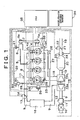
- Fig. 1 is an overall structural view of an internal combustion engine employing an exhaust gas purifying device of the invention, and of intake and exhaust systems of the internal combustion engine.
- An internal combustion engine 1 shown in Fig. 1 is a water-cooled four-stroke-cycle diesel engine having four cylinders 2.
- the internal combustion engine 1 has fuel injection valves 3, each of which directly injects fuel into a combustion chamber of a corresponding one of the cylinders 2.
- the fuel injection valves 3 are connected to an accumulator (common rail) 4 for accumulating fuel at a pressure equal to or lower than a predetermined pressure.
- the common rail 4 is fitted with a common rail pressure sensor 4a that outputs an electric signal corresponding to a pressure of fuel in the common rail 4.
- the common rail 4 communicates with a fuel pump 6 via a fuel supplying pipe 5.
- the fuel pump 6 operates using the rotational torque of an output shaft (crank shaft) of the internal combustion engine 1 as a driving source.
- a pump pulley 6a is coupled with a crank pulley 1a via a belt 7.
- the pump pulley 62 is mounted on an input shaft of the fuel pump 6.
- the crank pulley 1a is mounted on the output shaft (crank shaft) of the internal combustion engine 1.
- Fuel discharged from the fuel pump 6 is supplied to the common rail 4 via the fuel supplying pipe 5, is accumulated in the common rail 4 until it reaches the predetermined pressure, and is distributed to the fuel injection valves 3 disposed in the cylinders 2 respectively.
- the fuel injection valve 3 opens so that fuel is injected from the fuel injection valve 3 into a corresponding one of the cylinders 2.
- An intake manifold 8 is connected to the internal combustion engine 1. Each branch of the intake manifold 8 communicates with the combustion chamber of a corresponding one of the cylinders 2 via an intake port (not shown).
- the intake manifold 8 is connected to an intake pipe 9, which is connected to an air cleaner box 10.
- An air flow meter 11 and an intake air temperature sensor 12 are attached to the intake pipe 9 at positions downstream of the air cleaner box 10.
- the air flow meter 11 outputs an electric signal corresponding to a mass of intake air flowing through the intake pipe 9.
- the intake air temperature sensor 12 outputs an electric signal corresponding to a temperature of intake air flowing through the intake pipe 9.
- An intake throttle valve 13 for adjusting the flow rate of intake air flowing through the intake pipe 9 is disposed in the intake pipe 9 at a position immediately upstream of the intake manifold 8.
- the intake throttle valve 13 is fitted with an intake throttle actuator 14 that is constructed of a stepper motor or the like and that drives the intake throttle valve 13 in opening and closing directions.
- a compressor housing 15a of a centrifugal supercharger (turbocharger) 15 is disposed in the intake pipe 9 at a position between the air flow meter 11 and the intake throttle valve 13.
- the centrifugal supercharger 15 operates using thermal energy of exhaust gas as a driving source.
- An intercooler 16 for cooling intake air that has been compressed in the compressor housing 15a and heated to a high temperature is disposed in the intake pipe 9 at a position downstream of the compressor housing 15a.
- intake air that has flown into the air cleaner box 10 is removed of dust, dirt and the like by an air cleaner (not shown) in the air cleaner box 10, and then flows into the compressor housing 15a via the intake pipe 9.
- the intake air that has flown into the compressor housing 15a is compressed by rotation of a compressor wheel disposed inside the compressor housing 15a.
- the intake air that has been compressed in the compressor housing 15a and heated to a high temperature is cooled by the intercooler 16 and then flows into the intake manifold 8.
- the intake throttle valve 13 adjusts the flow rate of the intake air before it flows into the intake manifold 8.
- the intake air that has flown into the intake manifold 8 is distributed to the combustion chamber of each of the cylinders 2 via a corresponding branch. Fuel that has been injected from the fuel injection valve 3 of each of the cylinders 2 is used as an ignition source for burning the intake air.
- an exhaust manifold 18 is connected to the internal combustion engine 1.
- Each branch of the exhaust manifold 18 communicates with the combustion chamber of a corresponding one of the cylinders 2 via an exhaust port (not shown).
- the exhaust manifold 18 is connected to a turbine housing 15b of the centrifugal supercharger 15.
- the turbine housing 15b is connected to an exhaust pipe 19, which is connected at its downstream end to a muffler (not shown).
- the exhaust pipe 19 extends across an exhaust gas purifying catalyst 20 for purifying noxious gas components in exhaust gas.
- An air-fuel ratio sensor 23 and an exhaust gas temperature sensor 24 are attached to the exhaust pipe 19 at a position downstream of the exhaust gas purifying catalyst 20.
- the air-fuel ratio sensor 23 outputs an electric signal corresponding to an air-fuel ratio of exhaust gas flowing through the exhaust pipe 19.
- the exhaust gas temperature sensor 24 outputs an electric signal corresponding to a temperature of exhaust gas flowing through the exhaust pipe 19.
- An exhaust throttle valve 21 for adjusting the flow rate of exhaust gas flowing through the exhaust pipe 19 is disposed in the exhaust pipe 19 at a position downstream of the air-fuel ratio sensor 23 and the exhaust gas temperature sensor 24.
- the exhaust throttle valve 21 is fitted with an exhaust throttle actuator 22 that is constructed of a stepper motor or the like and that drives the exhaust throttle valve 21 in opening and closing directions.
- the mixture (burnt gas) that has been burnt in each of the cylinders 2 of the internal combustion engine 1 is discharged to the exhaust manifold 18 via the exhaust port, and then flows from the exhaust manifold 18 into the turbine housing 15b of the centrifugal supercharger 15.
- the exhaust gas that has flown into the turbine housing 15b has thermal energy, which is used to rotate a turbine wheel that is rotatably supported in the turbine housing 15b.
- the rotational torque of the turbine wheel is transmitted to the compressor wheel of the compressor housing 15a.
- the exhaust gas that has been discharged from the turbine housing 15b flows into the exhaust gas purifying catalyst 20 via the exhaust pipe 19, so that noxious gas components in the exhaust gas are removed or purified.
- the exhaust gas whose noxious gas components have been removed or purified by the exhaust gas purifying catalyst 20 is discharged into the atmosphere via the muffler. If need be, the exhaust throttle valve 21 adjusts the flow rate of the exhaust gas before it is discharged into the atmosphere.
- the exhaust manifold 18 communicates with the intake manifold 8 via an exhaust gas recirculation passage (EGR passage) 25 by which part of exhaust gas flowing through the exhaust manifold 18 is recirculated into the intake manifold 8.
- the EGR passage 25 extends across a flow rate adjusting valve (EGR valve) 26 that is constructed of an electromagnetic valve or the like and that changes the flow rate of exhaust gas flowing through the EGR passage 25 (hereinafter referred to as EGR gas) in accordance with the impressed current.
- EGR valve flow rate adjusting valve
- An EGR cooler 27 for cooling EGR gas flowing through the EGR passage 25 is disposed in the EGR passage 25 at a position upstream of the EGR valve 26.
- the EGR cooler 27 is designed to cause heat exchange between EGR gas flowing through the EGR passage 25 and a predetermined coolant so as to cool the EGR gas.
- the EGR gas that has been recirculated into the intake manifold 8 from the exhaust manifold 18 via the EGR passage 25 is introduced into the combustion chamber of each of the cylinders while mixing with fresh air that has flown from a region upstream of the intake manifold 8.
- Fuel injected from a corresponding one of the fuel injection valves 3 is used as an ignition source for burning the EGR gas.
- EGR gas itself is incombustible like water (H 2 O), carbon dioxide (CO 2 ), and the like and contains endothermic inert gas components. Therefore, if the mixture contains EGR gas, the combustion temperature of the mixture is lowered so that the amount of generation of nitrogen oxides (NOx) is reduced.
- EGR gas falls in temperature and decreases in volume if cooled in the EGR cooler 27.
- the exhaust gas purifying catalyst 20 is an NOx catalyst that purifies nitrogen oxides (NOx) in exhaust gas in the presence of a reducing agent. Although such an NOx catalyst ranges from a selective-reduction type NOx catalyst to an occlusion-reduction type NOx catalyst and the like, the following description will handle the occlusion-reduction type NOx catalyst as an example.
- the exhaust gas purifying catalyst 20 will be referred to as the occlusion-reduction type NOx catalyst 20.
- the occlusion-reduction type NOx catalyst 20 has a carrier made, for example, from alumina (Al 2 O 3 ).
- alumina Al 2 O 3
- at least one substance selected from an alkali metal such as potassium (K), sodium (Na), lithium (Li), and cesium (Cs), an alkali earth such as barium (Ba) and calcium (Ca), and a rare earth such as lanthanum (La) and yttrium (Y), and a noble metal such as platinum (Pt) are carried on the carrier.
- the occlusion-reduction type NOx catalyst 20 thus constructed occludes nitrogen oxides (NOx) in exhaust gas if the air-fuel ratio of exhaust gas flowing into the occlusion-reduction type NOx catalyst 20 (hereinafter referred to as the exhaust air-fuel ratio) is lean, and discharges, reduces, and purifies the occluded nitrogen oxides (NOx) if the exhaust gas flowing into the occlusion-reduction type NOx catalyst 20 has a reduced concentration of oxygen in the presence of a reducing agent.
- the exhaust air-fuel ratio the air-fuel ratio of exhaust gas flowing into the occlusion-reduction type NOx catalyst 20
- the exhaust air-fuel ratio means the ratio of the total amount of air supplied to an exhaust passage upstream of the exhaust gas purifying catalyst, combustion chambers, an intake passage, and the like to the total amount of fuel (hydrocarbon) supplied thereto. Accordingly, as long as no fuel, reducing agent, or air is supplied to the exhaust passage upstream of the occlusion-reduction type NOx catalyst 20, the exhaust air-fuel ratio coincides with the air-fuel ratio of the mixture supplied to the combustion chambers.
- occlusion-reduction type NOx catalyst 20 occludes and discharges NOx basically by a mechanism shown in Fig. 2. It is to be understood that "occlusion” used herein (in this specification) means retention of a substance (solid, liquid, gas molecules) in the form of at least one of adsorption, adhesion, absorption, trapping, storage, and others.
- the operation of occluding NOx as described above lasts as long as the air-fuel ratio of exhaust gas flowing into the occlusion-reduction type NOx catalyst is lean and as long as the NOx-occlusion capacity of the occlusion-reduction type NOx catalyst remains unsaturated.
- nitrogen oxides (NOx) occluded by the occlusion-reduction type NOx catalyst 20 in the form of nitrate ion (NO 3 - ) are converted into nitrogen dioxide (NO2) and nitrogen monoxide (NO) and are discharged from the occlusion-reduction type NOx catalyst 20.
- the nitrogen oxides (NOx) discharged from the occlusion-reduction type NOx catalyst 20 react with reducing components contained in exhaust gas (e.g. the activated versions of hydrocarbon (HC), carbon monoxide (CO), and the like that have been partially oxidized by reacting with oxygen O 2 - or O 2- on platinum (Pt) of the occlusion-reduction type NOx catalyst 20), and are reduced to nitrogen (N 2 ) and the like, as is apparent from Fig. 2B.
- reducing components contained in exhaust gas e.g. the activated versions of hydrocarbon (HC), carbon monoxide (CO), and the like that have been partially oxidized by reacting with oxygen O 2 - or O 2- on platinum (Pt) of the occlusion-reduction type NOx catalyst 20
- hydrocarbon (HC) and carbon monoxide (CO) in exhaust gas are oxidized by reacting with O 2 - or O 2- on platinum (Pt).
- the hydrocarbon (HC) and carbon monoxide (CO) react with the nitrogen oxides (NOx) discharged from the occlusion-reduction type NOx catalyst 20 and the nitrogen oxides (NOx) discharged from the internal combustion engine 1. Consequently, the nitrogen oxides (NOx) are reduced to nitrogen (N 2 ).
- the occlusion-reduction type NOx catalyst 20 is limited in NOx-occlusion capacity.
- the NOx-occlusion capacity of the occlusion-reduction type NOx catalyst 20 becomes saturated, so that nitrogen oxides (NOx) in exhaust gas are discharged into the atmosphere without being removed or purified by the occlusion-reduction type NOx catalyst 20.
- diesel engines such as the internal combustion engine 1 are designed such that the mixture having a lean air-fuel ratio is burnt in most of the operational ranges and that the air-fuel ratio of exhaust gas assumes a lean air-fuel ratio correspondingly in most of the operational ranges.
- the NOx-occlusion capacity of the occlusion-reduction type NOx catalyst 20 is likely to be saturated.
- the occlusion-reduction type NOx catalyst 20 is applied to a lean-burn internal combustion engine such as a diesel engine, it is required that the air-fuel ratio of exhaust gas be made stoichiometric or rich at a predetermined timing prior to saturation of the NOx-occlusion capacity of the occlusion-reduction type NOx catalyst 20.
- the internal combustion engine 1 is provided with a reducing agent supplying mechanism that adds fuel (light oil) as a reducing agent to exhaust gas flowing through the exhaust gas passage upstream of the occlusion-reduction type NOx catalyst 20.
- a reducing agent supplying mechanism that adds fuel (light oil) as a reducing agent to exhaust gas flowing through the exhaust gas passage upstream of the occlusion-reduction type NOx catalyst 20.
- the reducing agent supplying mechanism has a reducing agent injection valve 28, a reducing agent supplying passage 29, a flow rate adjusting valve 30, an emergency shut-off valve 31, and a reducing agent pressure sensor 32.
- the reducing agent injection valve 28 has an injection hole fitted to a cylinder head of the internal combustion engine 1 in such a manner as to face the inside of the exhaust manifold 18, and opens to inject fuel upon application of a fuel pressure equal to or higher than a predetermined opening pressure.
- Fuel discharged from the fuel pump 6 is introduced into the reducing agent injection valve 28 through the reducing agent supplying passage 29.
- the reducing agent supplying passage 29 extends across the flow rate adjusting valve 30, which adjusts the flow rate of fuel flowing through the reducing agent supplying passage 29.
- the emergency shut-off valve 31, which stops fuel from flowing through the reducing agent supplying passage 29, is disposed in the reducing agent supplying passage 29 at a position upstream of the flow rate adjusting valve 30.
- the reducing agent pressure sensor 32 is attached to the reducing agent supplying passage 29 at a position upstream of the flow rate adjusting valve 30 and is designed to output an electric signal corresponding to a pressure in the reducing agent supplying passage 29.
- the reducing agent injection valve 28 is preferably fitted to the cylinder head in such a manner as to have the injection hole located in the exhaust manifold 18 at a position downstream of a region where the exhaust manifold 18 is connected to the EGR passage 25, to protrude into the exhaust port of one of the cylinders 2 that is located closest to a converging portion of four branches of the exhaust manifold 18, and to face the converging portion of the exhaust manifold 18.
- the reducing agent injection valve 28 is fitted to the exhaust port of the first (#1) cylinder 2. However, if another one of the cylinders 2 is located closest to the converging portion of the exhaust manifold 18, the reducing agent injection valve 28 is fitted to the exhaust port of that cylinder 2.
- the reducing agent injection valve 28 be fitted in such a manner as to penetrate or adjoin a water jacket (not shown) formed in the cylinder head, and that the reducing agent injection valve 28 be cooled by coolant flowing through the water jacket.
- Such a reducing agent supplying mechanism is designed such that high-pressure fuel discharged from the fuel pump 6 is supplied to the reducing agent injection valve 28 via the reducing agent supplying passage 29 if the flow rate adjusting valve 30 is opened. If the pressure of the fuel supplied to the reducing agent injection valve 28 becomes equal to or higher than the opening pressure, the reducing agent injection valve 28 opens so that the fuel as a reducing agent is injected into the exhaust manifold 18.
- the reducing agent that has been injected into the exhaust manifold 18 from the reducing agent injection valve 28 flows into the turbine housing 15b together with exhaust gas that has flown from a region upstream of the exhaust manifold 18.
- the exhaust gas and the reducing agent that have flown into the turbine housing 15b are stirred by rotation of the turbine wheel and mixed with each other homogeneously, thus forming exhaust gas having a stoichiometric or rich air-fuel ratio.
- the stoichiometric or rich exhaust gas thus formed flows from the turbine housing 15b into the occlusion-reduction type NOx catalyst 20 via the exhaust pipe 19, whereby nitrogen oxides (NOx) occluded by the occlusion-reduction type NOx catalyst 20 are reduced to nitrogen (N 2 ) while being discharged.
- NOx nitrogen oxides
- the flow rate adjusting valve 30 is then closed to stop the reducing agent from being supplied to the reducing agent injection valve 28 from the fuel pump 6, the pressure of fuel supplied to the reducing agent injection valve 28 becomes lower than the aforementioned opening pressure. Consequently, the reducing agent injection valve 28 closes, so that the reducing agent is stopped from being supplied to the exhaust manifold 18.
- the internal combustion engine 1 constructed as described above is integrated with an electronic control unit (ECU) 35 for controlling the internal combustion engine 1.
- ECU electronice control unit
- the ECU 35 is designed to control the operational state of the internal combustion engine 1 in accordance with the operating conditions of the internal combustion engine 1 or a request from the driver.
- Various sensors including the common rail pressure sensor 4a, the airflow meter 11, the intake air temperature sensor 12, an intake pipe pressure sensor 17, the air-fuel ratio sensor 23, the exhaust gas temperature sensor 24, the reducing agent pressure sensor 32, a crank position sensor 33, a coolant temperature sensor 34, and an accelerator opening sensor 36 are connected to the ECU 35 via electric wires, so that output signals from these sensors are inputted to the ECU 35.
- the fuel injection valves 3, the intake throttle actuator 14, the exhaust throttle actuator 22, the EGR valve 26, the flow rate adjusting valve 30, the emergency shut-off valve 31, and the like are connected to the ECU 35 via electric wires, so that the ECU 35 can control these components.
- the ECU 35 has a CPU 351, a ROM 352, a RAM 353, a back-up RAM 354, an input port 356, and an output port 357, which are interconnected to one another by a bi-directional bus 350.
- the ECU 35 also has an A/D converter (A/D) 355 connected to the input port 356.
- A/D A/D converter
- the CPU 351 first determines whether or not a condition allowing the addition of a reducing agent has been fulfilled.
- this condition may be that the occlusion-reduction type NOx catalyst 20 has been activated, that the output signal value of the exhaust gas temperature sensor 24 (exhaust gas temperature) is equal to or lower than a predetermined upper limit value, that heat-up control or SOx poisoning recovery control is not being performed so as to recover the occlusion-reduction type NOx catalyst 20 from SOx poisoning, or the like.
- the CPU 351 controls the flow rate adjusting valve 30 such that the air-fuel ratio of exhaust gas flowing into the occlusion-reduction type NOx catalyst 20 is made stoichiometric or rich at intervals of a relatively short period in a spike manner, thus discharging and reducing nitrogen oxides (NOx) occluded by the occlusion-reduction type NOx catalyst 20 at intervals of a short period.
- NOx nitrogen oxides
- the CPU 351 reads out an engine speed stored in the RAM 353, an output signal of the accelerator opening sensor 36 (accelerator opening), an output signal value of the airflow meter 11 (amount of intake air), an amount of fuel injection, and the like. Using the engine speed, the accelerator opening, the amount of intake air, and the amount of fuel injection as parameters, the CPU 351 accesses a flow rate adjusting valve control map stored in the ROM 352 so as to calculate a timing for opening the flow rate adjusting valve 30. The CPU 351 opens the flow rate adjusting valve 30 at the timing thus calculated.
- high-pressure fuel discharged from the fuel pump 6 is supplied to the reducing agent injection valve 28 via the reducing agent supplying passage 29. If the pressure of fuel supplied to the reducing agent injection valve 28 becomes equal to or higher than an opening pressure, the reducing agent injection valve 28 opens so that fuel as a reducing agent is injected into the exhaust manifold 18.
- the reducing agent that has been injected into the exhaust manifold 18 from the reducing agent injection valve 28 mixes with exhaust gas that has flown from a region upstream of the exhaust manifold 18, thus forming exhaust gas having a stoichiometric or rich air-fuel ratio .
- Such stoichiometric or rich exhaust gas flows into the occlusion-reduction type NOx catalyst 20.
- the reducing agent supplying passage 29 is provided as a fuel supplying passage through which fuel as a reducing agent is supplied to the reducing agent injection valve 28 from the fuel pump 6.
- the reducing agent supplying passage 29 is designed to supply the reducing agent injection valve 28 constituting a fuel adding device with fuel via the flow rate adjusting valve 30.
- the flow rate adjusting valve 30 is a valve for regulating the amount of fuel to be added. As described above, the flow rate adjusting valve 30 has a preset opening so that the amount of fuel to be supplied is held constant. It is needless to mention that the opening of the flow rate adjusting valve 30 may be adjustable.
- the emergency shut-off valve 31 is disposed upstream of the flow rate adjusting valve 30 and downstream of the fuel pump 6 in Fig. 1.
- the emergency shut-off valve 31 is an electromagnetic valve having a movable core 52 equipped with a front end portion to which the reducing agent supplying passage 29 leads.
- An electromagnetic force generated by a solenoid coil 51 drives the movable core 52.
- the front end portion of the movable core 52 has a shut-off surface at a front end thereof, and a pressure-receiving surface on the side opposite to the shut-off surface.
- the shut-off surface comes into abutment on an outlet leading to the downstream side and thus stops fuel from flowing through the reducing agent supplying passage 29.
- the pressure-receiving surface receives a pressure of fuel flowing from a region upstream of the reducing agent supplying passage 29.
- the electromagnetic force of the solenoid coil 51 is set as follows. If there is no difference between an inlet fuel pressure P1 and an outlet fuel pressure P2 in the emergency shut-off valve 31, the movable core 52 can be driven and thus the emergency shut-off valve 31 can be opened and closed. If the inlet fuel pressure P1 is higher than the outlet fuel pressure P2, the emergency shut-off valve 31 cannot be driven from a closed position to an open position due to a differential pressure P1-P2.
- the air-fuel ratio sensor 23 is connected to the input port of the ECU 35.
- a fuel leakage determining means for making a determination on fuel leakage in accordance with data outputted from the air-fuel ratio sensor 23 is stored in the ROM 352.
- the ECU 35 as a driving control means also performs driving control of the emergency shut-off valve 31.
- step 101 it is determined in step 101 whether or not a fuel adding system suffers a malfunction. That is, it is determined whether or not a malfunction flag for the fuel adding system has been set as 1 since last execution of the present routine. If the malfunction flag has been set as 1, it is determined that the fuel adding system suffers a malfunction. If the malfunction flag has not been set as 1, the fuel adding system does not suffer a malfunction. Thus, the process proceeds to step 102 where it is determined whether or not a performance flag for the addition of fuel has been set as 1.
- step 112 the malfunction flag for the fuel adding system, which was set as 1 during last execution of the present routine, is maintained as it is. Then, the warning lamp is lit up in step 113.
- step 102 If the performance flag for the addition of fuel has not been set as 1 in step 102, that is, if no instruction to perform the addition of fuel has been issued, the process proceeds to step 103 where the engine air-fuel ratio (intake air-fuel ratio) and the air-fuel ratio of exhaust gas detected by the air-fuel ratio sensor 23 are inputted. If the performance flag for the addition of fuel has been set as 1 in step 102, the process proceeds to step 114 where the addition of exhaust fuel is performed.
- step 115 the air-fuel ratio of exhaust gas and the air-fuel ratio of intake air are inputted in step 115.
- the process then proceeds to step 116 where it is determined whether or not the air-fuel ratio of exhaust gas is smaller than a predetermined value Y such as an engine base air-fuel ratio. If the air-fuel ratio of exhaust gas is smaller than the predetermined value, the present routine is terminated immediately. If the result in step 116 is negative, it is determined that a reducing agent is being supplied inappropriately. The process then proceeds to step 112.
- a predetermined value Y such as an engine base air-fuel ratio
- the inappropriate supply of the reducing agent during the addition of fuel is regarded as ascribable to the clogging of a nozzle for adding fuel, an insufficient feed pressure of fuel based on leakage of fuel to the outside from a line for adding fuel, the inability to open the emergency shut-off valve 31, a malfunction in opening the valve for regulating the amount of fuel to be added, or the like.
- step 103 the air-fuel ratio of exhaust gas and the engine air-fuel ratio are inputted.
- step 104 it is determined whether or not the exhaust air-fuel ratio is smaller than a predetermined value X such as a stoichiometric air-fuel ratio. If the exhaust air-fuel ratio is smaller than the predetermined value X, the process proceeds to step 112 where the malfunction flag for the fuel adding system is set as 1.
- the exhaust air-fuel ratio is smaller than the stoichiometric air-fuel ratio, for example, if fuel is injected into the exhaust pipe without interruption. Such continuous injection of fuel is considered to result, for example, from a malfunction of the flow rate adjusting valve 30. If the exhaust air-fuel ratio is greater than the predetermined value in step 104, the emergency shut-off valve 31 is closed (step 105).
- step 106 the value of a counter C is incremented by 1. This incremental operation in step 106 is repeated until the counter C reaches a value equal to or greater than a predetermined value Cb in step 107. If the counter C reaches a value equal to or greater than Cb, the process proceeds to step 108 where the emergency shut-off valve 31 is opened. That is, the aforementioned steps 105 to 108 are designed such that the emergency shut-off valve 31 remains closed for a predetermined period and then is opened. In this case, a first electromagnetic valve (the solenoid coil 51) of the emergency shut-off valve 31 is used. Should fuel leakage occur in the fuel adding system, the outlet fuel pressure P2 becomes lower than the inlet fuel pressure P1 in the emergency shut-off valve 31. The movable core 52 is unable to move due to the differential pressure P1-P2, so that the emergency shut-off valve 31 remains closed and cannot be opened.
- the solenoid coil 51 the solenoid coil 51
- step 109 If the performance flag for the addition of exhaust fuel is set as 1 in step 109 on the condition that the emergency shut-off valve 31 be open in step 108, the addition of fuel is performed. Then, exhaust air-fuel ratios during the addition of fuel are inputted in a time-series manner in step 110.
- the fuel leakage determining means determines in step 111 whether or not the exhaust air-fuel ratios thus inputted are arranged in such an order as to decrease gradually with the lapse of time. If these exhaust air-fuel ratios are not arranged in such an order as to decrease gradually with the lapse of time, it is apparent that the exhaust air-fuel ratio has not shifted to the rich side. This means that the outlet fuel pressure P2 becomes lower than the inlet fuel pressure P1 in the emergency shut-off valve 31 due to fuel leakage, that the movable core 52 is unable to move due to the differential pressure P1-P2, that the emergency shut-off valve 31 remains closed, and that the operation of supplying fuel to be added has been stopped.
- step 112 the malfunction flag for the fuel adding system is set as 1.
- this embodiment is designed such that the outlet fuel pressure P2 becomes lower than the inlet fuel pressure P1 in the emergency shut-off valve 31 upon the occurrence of fuel leakage, that the movable core 52 is unable to move due to the differential pressure P1-P2, and that the emergency shut-off valve 31 remains closed, thus making it possible to prevent further escalation of the inconvenience of fuel leakage.
- Such a method makes it possible to detect fuel leakage more easily and less expensively as compared with the case where the fuel adding system is further provided with a pressure sensor.
- the emergency shut-off valve 31 has a two-stage structure composed of a first electromagnetic valve and a second electromagnetic valve (a first solenoid coil 51a and a second solenoid coil 51b) as shown in Fig. 7.
- the emergency shut-off valve 31 of this embodiment is an electromagnetic valve having a movable core 52 equipped with a front end portion to which the reducing agent supplying passage 29 leads. During normal operation, the movable core 52 is driven by an electromagnetic force generated by the first solenoid coil 51a.
- the front end portion of the movable core 52 has a shut-off surface at a front end thereof, and a pressure-receiving surface on the side opposite to the shut-off surface.
- the shut-off surface comes into abutment on the outlet leading to the downstream side and thus stops fuel from flowing through the reducing agent supplying passage 29.
- the pressure-receiving surface receives a pressure of fuel flowing from the region upstream of the reducing agent supplying passage 29.
- the electromagnetic force of the first solenoid coil 51a is set as follows. If there is no difference between the inlet fuel pressure P1 and the outlet fuel pressure P2 in the emergency shut-off valve 31, the movable core 52 can be driven and thus the emergency shut-off valve 31 can be opened and closed. If the inlet fuel pressure P1 is higher than the outlet fuel pressure P2, the emergency shut-off valve 31 cannot be driven from a closed position to an open position due to the differential pressure P1-P2.
- Fig. 8 is a flowchart showing an example of control that is performed in this second embodiment to make a determination on the leakage of fuel to be added.
- step 201 it is determined in step 201 whether or not the malfunction flag for the fuel adding system has been set as 1. If the malfunction flag for the fuel adding system has been set as 1, the process proceeds to step 212 where the malfunction flag is held at 1. Then, the warning lamp is lit up (step 213), and the present routine is terminated temporarily.
- step 201 determines whether or not the performance flag for the addition of fuel has been set as 1. If the performance flag has been set as 1, it is assumed that an instruction to perform the addition of fuel has been issued. Thus, the process proceeds to step 214 where the addition of exhaust fuel is performed. Then, the air-fuel ratio of exhaust gas and the engine air-fuel ratio are inputted in step 215. It is determined herein whether or not the exhaust air-fuel ratio is smaller than a predetermined value Y such as an engine base air-fuel ratio (step 216). If the exhaust air-fuel ratio is smaller than the engine base air-fuel ratio, the present routine is terminated immediately. On the contrary, if the exhaust air-fuel ratio is not smaller than the engine base air-fuel ratio, it is determined that a reducing agent is being supplied inappropriately during the addition of fuel. Then, the process proceeds to step 212.
- a predetermined value Y such as an engine base air-fuel ratio
- step 203 the exhaust air-fuel ratio and the engine air-fuel ratio are inputted. It is determined herein whether or not the exhaust air-fuel ratio is smaller than a predetermined value X such as a stoichiometric air-fuel ratio (step 204). If the exhaust air-fuel ratio is smaller than the stoichiometric air-fuel ratio in step 204, the process proceeds to step 212 on the assumption that there is a malfunction. This results from the same cause as in the case of the aforementioned control example.
- a predetermined value X such as a stoichiometric air-fuel ratio
- step 205 the emergency shut-off valve 31 is closed.
- the value of the counter C is incremented in step 206 and step 207 as in the case of the aforementioned control example. If it is determined that the counter C has reached a value equal to or greater than the predetermined value Cb, the emergency shut-off valve 31 is opened in step 208. That is, the emergency shut-off valve 31 remains closed for a predetermined period and then is opened. In this case, the first electromagnetic valve (the first solenoid coil 51a) of the emergency shut-off valve 31 is used.
- the outlet fuel pressure P2 becomes lower than the inlet fuel pressure P1 in the emergency shut-off valve 31.
- the movable core 52 is unable to move due to the differential pressure P1-P2, so that the emergency shut-off valve 31 remains closed and cannot be opened.
- the performance flag for the addition of exhaust fuel is set as 1 in step 209 after the emergency shut-off valve 31 has been opened in step 208. Then, exhaust air-fuel ratios during the addition of fuel are inputted in a time-series manner in step 210. It is determined in step 211 whether or not the exhaust air-fuel ratios thus inputted are arranged in such an order as to decrease gradually. If these exhaust air-fuel ratios are not arranged in such an order as to decrease gradually, it is apparent that the air-fuel ratio has not shifted to the rich side despite the addition of fuel. Therefore, the malfunction flag is set as 1 in step 212 on the assumption that the fuel adding system suffers a malfunction.
- step 217 the emergency shut-off valve 31 is closed by an electromagnetic force of the first solenoid coil 51a. Then, an instruction to add fuel is issued in step 218 while maintaining the emergency shut-off valve 31 closed.
- the performance flag for the addition of exhaust fuel is set as 1.
- step 219. If the exhaust air-fuel ratio becomes lean despite the addition of fuel, it is determined that the emergency shut-off valve 31 is closed normally. If the exhaust air-fuel ratio during the addition of fuel is rich, it is determined that the emergency shut-off valve 31 confronts a closure failure. That is, it is determined in step 220 whether or not the exhaust air-fuel ratios are arranged in such an order as to decrease gradually. If the exhaust air-fuel ratios are arranged in such an order as to decrease gradually, the malfunction flag is set as 1 in step 212. If the exhaust air-fuel ratios are not arranged in such an order as to decrease gradually, the process proceeds to step 221 where the emergency shut-off valve 31 is opened by an electromagnetic force of the second electromagnetic valve (the second solenoid coil 51b).
- step 111 of the first embodiment fuel is added by opening the reducing agent injection valve 28 on the condition that the emergency shut-off valve 31 be closed in advance in step 217.
- the emergency shut-off valve 31 is closed normally, the exhaust air-fuel ratios ought not to be arranged in such an order as to decrease gradually in step 220. Namely, the air-fuel ratio ought not to have shifted to the rich side in step 220.
- the exhaust air-fuel ratios are not arranged in such an order as to decrease gradually in step 220, normal operation of the emergency shut-off valve 31 is confirmed.
- the reducing agent injection valve 28 is opened on the condition that the emergency shut-off valve 31 be closed in step 217, the outlet fuel pressure P2 becomes lower than the inlet fuel pressure P1 in the emergency shut-off valve 31.
- the movable core 52 is unable to move due to the differential pressure P1-P2, and the emergency shut-off valve 31 remains closed and cannot be opened.
- the movable core 52 is driven due to application of an electromagnetic force from the second solenoid coil 51b in step 221.
- the emergency shut-off valve 31 in the case where the addition of fuel is performed while the emergency shut-off valve 31 is closed, if fuel in the fuel line is added, the operation of supplying fuel is stopped and the exhaust air-fuel ratio does not shift despite the issuance of an instruction to add more fuel. However, should the output of the exhaust air-fuel ratio sensor 23 demonstrate a change, it can be determined that the emergency shut-off valve 31 is in a state of leakage (closure failure). In the case where the emergency shut-off valve 31 is in normal operation, if the addition of fuel is started when the emergency shut-off valve 31 is closed, it becomes impossible to open the emergency shut-off valve 31 afterwards.
- the emergency shut-off valve 31 can be opened and closed irrespective of the differential pressure between the inlet fuel pressure P1 and the outlet fuel pressure P2 in the emergency shut-off valve 31 if the two-stage structure composed of the two electromagnetic valves as in the case of this embodiment is adopted.
- the embodiments of the invention are designed such that the emergency shut-off valve for shutting off the fuel line in the event of fuel leakage is constructed as described above, and that it is impossible to open the emergency shut-off valve despite the issuance of an opening signal once a differential pressure is generated across the valve during closure thereof, thus making it possible to forcefully hold the shut-off valve closed in the event of fuel leakage. Hence, further escalation of the inconvenience can be prevented.
- An exhaust gas purifying device of the invention comprises an exhaust gas purifying catalyst (20) disposed in an exhaust system, a fuel adding device (28) for adding fuel to the exhaust gas purifying catalyst (20) as a reducing agent, a fuel supplying source (6) for supplying the fuel adding device (28) with fuel, an emergency shut-off valve (31) disposed in a fuel supplying passage (29) that connects the fuel supplying source (6) to the fuel adding device (28), and a shut-off valve position detecting means for detecting that the emergency shut-off valve (31) is closed. If an upstream fuel pressure applied to the emergency shut-off valve (31) becomes higher than a downstream fuel pressure applied to the emergency shut-off valve (31), the emergency shut-off valve (31) is controlled so as to be prevented from being opened. If the exhaust air-fuel ratio does not shift to the rich side despite the issuance of an instruction to add fuel at this moment, it is possible to detect that fuel leakage has occurred downstream of the emergency shut-off valve (31).
Abstract
Description
- The invention relates to an exhaust gas purifying device for an internal combustion engine, and more particularly, to an exhaust gas purifying device designed to add a reducing agent such as fuel to a catalyst.
- An exhaust gas purifying device for adding a reducing agent such as fuel to discharge and reduce NOx absorbed by an occlusion-reduction type catalyst is disclosed, for example, in Japanese Patent Application Laid-Open No. 11-98641.
- This is an exhaust gas purifying device for an internal combustion engine in which combustion occurs at a lean air-fuel ratio. Exhaust gas discharged therefrom is introduced into an exhaust passage and purified by a catalyst disposed in the exhaust passage. The exhaust passage diverges into first and second exhaust passages. This exhaust gas purifying device is characterized by comprising a flow passage switching means, an occlusion-reduction type catalyst, a selective-reduction type catalyst, and a reducing agent adding means . The flow passage switching means switches the flow passage of exhaust gas such that exhaust gas flows through the second exhaust passage when the temperature thereof falls and that exhaust gas flows through the first exhaust passage when the temperature thereof does not fall. The occlusion-reduction type catalyst, which is disposed in the first exhaust passage, absorbs NOx when the air-fuel ratio of exhaust gas flowing thereinto is lean, and discharges the NOx thus absorbed when the concentration of oxygen in the exhaust gas drops. The selective-reduction type catalyst, which is disposed in the second exhaust passage, reduces or decomposes NOx in the presence of hydrocarbon under the atmosphere containing an excessive concentration of oxygen. The reducing agent adding means adds a reducing agent to the occlusion-reduction type catalyst while exhaust gas flows through the second exhaust passage, thus ensuring that the NOx absorbed by the occlusion-reduction type catalyst are discharged and reduced.
- Such a device can use fuel in the internal combustion engine as a reducing agent. In this case, it is customary to supply the fuel adding device with fuel through a passage diverging from a fuel supplying pump of the internal combustion engine.
- Such a device may possibly suffer a malfunction such as fuel leakage in a region extending from the fuel supplying pump to the fuel adding device. However, no method for detecting the occurrence of fuel leakage in the fuel adding device has been proposed.
- Should fuel leakage occur in the fuel adding device, the catalyst is no longer supplied with fuel as a reducing agent. This leads to a deterioration in the NOx purification ratio. Further, fuel is injected to the catalyst without interruption so that the catalyst may be damaged. Thus, in the event of fuel leakage in the exhaust fuel adding device, a means for detecting the occurrence of fuel leakage and forcefully stopping fuel from being supplied is required.
- It is an object of the invention to provide an exhaust gas purifying device capable of detecting the occurrence of fuel leakage in a device that is designed to add fuel to an exhaust gas purifying catalyst as a reducing agent.
- An exhaust gas purifying device according to a first aspect of the invention comprises an exhaust gas purifying catalyst disposed in an exhaust system, a fuel adding device for adding fuel to the exhaust gas purifying catalyst as a reducing agent, a fuel supplying source for supplying the fuel adding device with fuel, an emergency shut-off valve disposed in a fuel supplying passage that connects the fuel supplying source to the fuel adding device, and shut-off valve position detecting means for detecting that the emergency shut-off valve is closed. The emergency shut-off valve is controlled such that, if an upstream fuel pressure applied to the emergency shut-off valve becomes higher than a downstream fuel pressure applied to the emergency shut-off valve, the emergency shut-off valve cannot be opened despite the issuance of an instruction to open the same.
- In the aforementioned first aspect of the invention, if the upstream fuel pressure applied to the emergency shut-off valve becomes higher than the downstream fuel pressure applied to the emergency shut-off valve, it is inferable that fuel leakage has occurred downstream of the emergency shut-off valve. Hence, the emergency shut-off valve is forced to remain closed, whereby further escalation of fuel leakage can be prevented.
- Herein, after the issuance of an instruction to open the emergency shut-off valve, it is determined whether or not the emergency shut-off valve has been opened. If it is determined that the emergency shut-off valve remains closed despite the issuance of the instruction to open the same, it can be concluded that the leakage of fuel to be added has occurred downstream of the emergency shut-off valve and that the upstream fuel pressure applied to the emergency shut-off valve has thus become higher than the downstream fuel pressure applied to the emergency shut-off valve.
- In the case where an exhaust air-fuel ratio detecting means for detecting an exhaust air-fuel ratio is provided so as to detect whether or not the emergency shut-off valve is closed, the exhaust air-fuel ratio during closure of the emergency shut-off valve is detected by means of the exhaust air-fuel ratio detecting means. An instruction to open the emergency shut-off valve is then issued. Also, the exhaust air-fuel ratio detecting means then detects exhaust air-fuel ratios sequentially after the issuance of an instruction to add fuel. If the exhaust air-fuel ratios thus detected are not arranged in such an order as to shift to the rich side with the lapse of time, it can be determined that fuel leakage has occurred in the fuel adding system downstream of the emergency shut-off valve. That is, if the exhaust air-fuel ratio detecting means detects that the exhaust air-fuel ratio does not become rich despite the issuance of an instruction to add fuel, the occurrence of leakage of fuel to be added downstream of the emergency shut-off valve is detected.
- Means other than the aforementioned one can also be employed to detect whether or not the emergency shut-off valve is closed. For example, it is possible to employ a sensor for detecting the position of the shut-off valve, the temperature of exhaust gas, a deterioration in the purification performance of the exhaust gas purifying catalyst, or the like.
- It is preferable that the emergency shut-off valve have a two-stage structure composed of first and second driving means, that the emergency shut-off valve be driven in opening and closing directions by a driving force of the first driving means during normal operation, and that the emergency shut-off valve cannot be opened by a driving force of the first driving means but can be opened upon application of a driving force of the second driving means if the fuel pressure upstream of the emergency shut-off valve becomes higher than the fuel pressure downstream of the emergency shut-off valve.
- Furthermore, it is more preferable that the exhaust air-fuel ratio detecting means detect an exhaust air-fuel ratio when the emergency shut-off valve is open, that an instruction to close the emergency shut-off valve be then issued, that the exhaust air-fuel ratio detecting means then detect exhaust air-fuel ratios sequentially after the issuance of an instruction to add fuel, and that the emergency shut-off valve be regarded as having been closed normally and be opened by the second driving means if the exhaust air-fuel ratios thus detected are not arranged in such an order as to shift to the rich side with the lapse of time.
-
- Fig. 1 is an overall structural view of an internal combustion engine employing a malfunction detecting device of a reducing agent supplying apparatus according to embodiments of the invention, and of intake and exhaust systems of the internal combustion engine.
- Fig. 2A is a view for illustrating the mechanism by which an occlusion-reduction type NOx catalyst occludes NOx.
- Fig. 2B is a view for illustrating the mechanism by which the occlusion-reduction type NOx catalyst discharges NOx.
- Fig. 3 is a block diagram showing the internal structure of an ECU.
- Fig. 4 shows a structural example of the essential part of a first embodiment of the invention.
- Fig. 5 is a structural view of an emergency shut-off valve.
- Fig. 6 is a flowchart showing the procedure of performing driving control of the emergency shut-off valve.
- Fig. 7 is a structural view of another emergency shut-off valve of a second embodiment of the invention.
- Fig. 8 is a flowchart showing the procedure of performing driving control of the emergency shut-off valve shown in Fig. 7.
-
- Hereinafter, concrete embodiments of an exhaust gas purifying device according to the invention will be described with reference to the drawings. The description will be made herein referring to an exemplary case in which the invention is applied to a diesel engine for driving a vehicle.
- Fig. 1 is an overall structural view of an internal combustion engine employing an exhaust gas purifying device of the invention, and of intake and exhaust systems of the internal combustion engine. An
internal combustion engine 1 shown in Fig. 1 is a water-cooled four-stroke-cycle diesel engine having fourcylinders 2. - The
internal combustion engine 1 hasfuel injection valves 3, each of which directly injects fuel into a combustion chamber of a corresponding one of thecylinders 2. Thefuel injection valves 3 are connected to an accumulator (common rail) 4 for accumulating fuel at a pressure equal to or lower than a predetermined pressure. Thecommon rail 4 is fitted with a commonrail pressure sensor 4a that outputs an electric signal corresponding to a pressure of fuel in thecommon rail 4. - The
common rail 4 communicates with afuel pump 6 via a fuel supplying pipe 5. Thefuel pump 6 operates using the rotational torque of an output shaft (crank shaft) of theinternal combustion engine 1 as a driving source. Apump pulley 6a is coupled with a crank pulley 1a via abelt 7. The pump pulley 62 is mounted on an input shaft of thefuel pump 6. The crank pulley 1a is mounted on the output shaft (crank shaft) of theinternal combustion engine 1. - In a fuel injection system thus constructed, if a rotational torque of the crank shaft is transmitted to the input shaft of the
fuel pump 6, thefuel pump 6 discharges fuel at a pressure corresponding to the rotational torque that has been transmitted to the input shaft of thefuel pump 6 from the crank shaft. - Fuel discharged from the
fuel pump 6 is supplied to thecommon rail 4 via the fuel supplying pipe 5, is accumulated in thecommon rail 4 until it reaches the predetermined pressure, and is distributed to thefuel injection valves 3 disposed in thecylinders 2 respectively. Upon application of a driving current to each of thefuel injection valves 3, thefuel injection valve 3 opens so that fuel is injected from thefuel injection valve 3 into a corresponding one of thecylinders 2. - An intake manifold 8 is connected to the
internal combustion engine 1. Each branch of the intake manifold 8 communicates with the combustion chamber of a corresponding one of thecylinders 2 via an intake port (not shown). - The intake manifold 8 is connected to an
intake pipe 9, which is connected to an aircleaner box 10. Anair flow meter 11 and an intakeair temperature sensor 12 are attached to theintake pipe 9 at positions downstream of theair cleaner box 10. Theair flow meter 11 outputs an electric signal corresponding to a mass of intake air flowing through theintake pipe 9. The intakeair temperature sensor 12 outputs an electric signal corresponding to a temperature of intake air flowing through theintake pipe 9. - An
intake throttle valve 13 for adjusting the flow rate of intake air flowing through theintake pipe 9 is disposed in theintake pipe 9 at a position immediately upstream of the intake manifold 8. Theintake throttle valve 13 is fitted with anintake throttle actuator 14 that is constructed of a stepper motor or the like and that drives theintake throttle valve 13 in opening and closing directions. - A
compressor housing 15a of a centrifugal supercharger (turbocharger) 15 is disposed in theintake pipe 9 at a position between theair flow meter 11 and theintake throttle valve 13. Thecentrifugal supercharger 15 operates using thermal energy of exhaust gas as a driving source. Anintercooler 16 for cooling intake air that has been compressed in thecompressor housing 15a and heated to a high temperature is disposed in theintake pipe 9 at a position downstream of thecompressor housing 15a. - In an intake system thus constructed, intake air that has flown into the
air cleaner box 10 is removed of dust, dirt and the like by an air cleaner (not shown) in theair cleaner box 10, and then flows into thecompressor housing 15a via theintake pipe 9. - The intake air that has flown into the
compressor housing 15a is compressed by rotation of a compressor wheel disposed inside thecompressor housing 15a. The intake air that has been compressed in thecompressor housing 15a and heated to a high temperature is cooled by theintercooler 16 and then flows into the intake manifold 8. If need be, theintake throttle valve 13 adjusts the flow rate of the intake air before it flows into the intake manifold 8. The intake air that has flown into the intake manifold 8 is distributed to the combustion chamber of each of thecylinders 2 via a corresponding branch. Fuel that has been injected from thefuel injection valve 3 of each of thecylinders 2 is used as an ignition source for burning the intake air. - On the other hand, an
exhaust manifold 18 is connected to theinternal combustion engine 1. Each branch of theexhaust manifold 18 communicates with the combustion chamber of a corresponding one of thecylinders 2 via an exhaust port (not shown). - The
exhaust manifold 18 is connected to a turbine housing 15b of thecentrifugal supercharger 15. The turbine housing 15b is connected to anexhaust pipe 19, which is connected at its downstream end to a muffler (not shown). - The
exhaust pipe 19 extends across an exhaustgas purifying catalyst 20 for purifying noxious gas components in exhaust gas. An air-fuel ratio sensor 23 and an exhaustgas temperature sensor 24 are attached to theexhaust pipe 19 at a position downstream of the exhaustgas purifying catalyst 20. The air-fuel ratio sensor 23 outputs an electric signal corresponding to an air-fuel ratio of exhaust gas flowing through theexhaust pipe 19. The exhaustgas temperature sensor 24 outputs an electric signal corresponding to a temperature of exhaust gas flowing through theexhaust pipe 19. - An
exhaust throttle valve 21 for adjusting the flow rate of exhaust gas flowing through theexhaust pipe 19 is disposed in theexhaust pipe 19 at a position downstream of the air-fuel ratio sensor 23 and the exhaustgas temperature sensor 24. Theexhaust throttle valve 21 is fitted with anexhaust throttle actuator 22 that is constructed of a stepper motor or the like and that drives theexhaust throttle valve 21 in opening and closing directions. - In an exhaust system thus constructed, the mixture (burnt gas) that has been burnt in each of the
cylinders 2 of theinternal combustion engine 1 is discharged to theexhaust manifold 18 via the exhaust port, and then flows from theexhaust manifold 18 into the turbine housing 15b of thecentrifugal supercharger 15. The exhaust gas that has flown into the turbine housing 15b has thermal energy, which is used to rotate a turbine wheel that is rotatably supported in the turbine housing 15b. Herein, the rotational torque of the turbine wheel is transmitted to the compressor wheel of thecompressor housing 15a. - The exhaust gas that has been discharged from the turbine housing 15b flows into the exhaust
gas purifying catalyst 20 via theexhaust pipe 19, so that noxious gas components in the exhaust gas are removed or purified. The exhaust gas whose noxious gas components have been removed or purified by the exhaustgas purifying catalyst 20 is discharged into the atmosphere via the muffler. If need be, theexhaust throttle valve 21 adjusts the flow rate of the exhaust gas before it is discharged into the atmosphere. - Further, the
exhaust manifold 18 communicates with the intake manifold 8 via an exhaust gas recirculation passage (EGR passage) 25 by which part of exhaust gas flowing through theexhaust manifold 18 is recirculated into the intake manifold 8. TheEGR passage 25 extends across a flow rate adjusting valve (EGR valve) 26 that is constructed of an electromagnetic valve or the like and that changes the flow rate of exhaust gas flowing through the EGR passage 25 (hereinafter referred to as EGR gas) in accordance with the impressed current. - An
EGR cooler 27 for cooling EGR gas flowing through theEGR passage 25 is disposed in theEGR passage 25 at a position upstream of theEGR valve 26. - In an exhaust gas recirculation mechanism thus constructed, if the
EGR valve 26 is opened, theEGR passage 25 becomes passable, so that part of the exhaust gas flowing through theexhaust manifold 18 flows into theEGR passage 25 and is introduced into the intake manifold 8 via theEGR cooler 27. - Herein, the
EGR cooler 27 is designed to cause heat exchange between EGR gas flowing through theEGR passage 25 and a predetermined coolant so as to cool the EGR gas. - The EGR gas that has been recirculated into the intake manifold 8 from the
exhaust manifold 18 via theEGR passage 25 is introduced into the combustion chamber of each of the cylinders while mixing with fresh air that has flown from a region upstream of the intake manifold 8. Fuel injected from a corresponding one of thefuel injection valves 3 is used as an ignition source for burning the EGR gas. - It is to be noted herein that EGR gas itself is incombustible like water (H2O), carbon dioxide (CO2), and the like and contains endothermic inert gas components. Therefore, if the mixture contains EGR gas, the combustion temperature of the mixture is lowered so that the amount of generation of nitrogen oxides (NOx) is reduced.
- Furthermore, EGR gas falls in temperature and decreases in volume if cooled in the
EGR cooler 27. Thus, when EGR gas is supplied to the combustion chamber, the temperature of atmosphere in the combustion chamber is prevented from rising unnecessarily, and the amount (volume) of fresh air supplied to the combustion chamber is prevented from decreasing unnecessarily. - Next, the exhaust
gas purifying catalyst 20 according to this embodiment will be described specifically. - The exhaust
gas purifying catalyst 20 is an NOx catalyst that purifies nitrogen oxides (NOx) in exhaust gas in the presence of a reducing agent. Although such an NOx catalyst ranges from a selective-reduction type NOx catalyst to an occlusion-reduction type NOx catalyst and the like, the following description will handle the occlusion-reduction type NOx catalyst as an example. Hereinafter, the exhaustgas purifying catalyst 20 will be referred to as the occlusion-reductiontype NOx catalyst 20. - The occlusion-reduction
type NOx catalyst 20 has a carrier made, for example, from alumina (Al2O3). For example, at least one substance selected from an alkali metal such as potassium (K), sodium (Na), lithium (Li), and cesium (Cs), an alkali earth such as barium (Ba) and calcium (Ca), and a rare earth such as lanthanum (La) and yttrium (Y), and a noble metal such as platinum (Pt) are carried on the carrier. - The occlusion-reduction
type NOx catalyst 20 thus constructed occludes nitrogen oxides (NOx) in exhaust gas if the air-fuel ratio of exhaust gas flowing into the occlusion-reduction type NOx catalyst 20 (hereinafter referred to as the exhaust air-fuel ratio) is lean, and discharges, reduces, and purifies the occluded nitrogen oxides (NOx) if the exhaust gas flowing into the occlusion-reductiontype NOx catalyst 20 has a reduced concentration of oxygen in the presence of a reducing agent. - It is to be noted herein that the exhaust air-fuel ratio means the ratio of the total amount of air supplied to an exhaust passage upstream of the exhaust gas purifying catalyst, combustion chambers, an intake passage, and the like to the total amount of fuel (hydrocarbon) supplied thereto. Accordingly, as long as no fuel, reducing agent, or air is supplied to the exhaust passage upstream of the occlusion-reduction
type NOx catalyst 20, the exhaust air-fuel ratio coincides with the air-fuel ratio of the mixture supplied to the combustion chambers. - The mechanism by which the occlusion-reduction
type NOx catalyst 20 occludes and discharges NOx will now be described on the basis of an occlusion-reduction type NOx catalyst having platinum (Pt) and barium (Ba) carried on a carrier made from alumina. - It is considered that the occlusion-reduction
type NOx catalyst 20 occludes and discharges NOx basically by a mechanism shown in Fig. 2. It is to be understood that "occlusion" used herein (in this specification) means retention of a substance (solid, liquid, gas molecules) in the form of at least one of adsorption, adhesion, absorption, trapping, storage, and others. - First of all, if the air-fuel ratio of exhaust gas flowing into the occlusion-reduction
type NOx catalyst 20 becomes lean so that the concentration of oxygen in the exhaust gas is increased, oxygen (O2) in the exhaust gas adheres to the surface of platinum (Pt) in the form of O2 - or O2-, and nitrogen monoxide (NO) in the exhaust gas reacts with O2 - or O2- on the surface of platinum (Pt) to form nitrogen dioxide (NO2) (2NO+O2→NO2), as is apparent from Fig. 2A. Nitrogen dioxide (NO2) is combined with barium oxide (BaO) while being oxidized on the surface of platinum (Pt), thus forming nitrate ion (NO3 -). Thus, the occlusion-reduction type NOx catalyst occludes nitrogen oxides (NOx) in exhaust gas as nitrate ion (NO3 -). - The operation of occluding NOx as described above lasts as long as the air-fuel ratio of exhaust gas flowing into the occlusion-reduction type NOx catalyst is lean and as long as the NOx-occlusion capacity of the occlusion-reduction type NOx catalyst remains unsaturated.
- On the other hand, as shown in Fig. 2B, if the concentration of oxygen flowing into the occlusion-reduction
type NOx catalyst 20 decreases, the amount of production of nitrogen dioxide (NO2) decreases. Therefore, the nitrate ion (NO3 -) combined with barium oxide (BaO) reverts to nitrogen dioxide (NO2) and nitrogen monoxide (NO) and is removed from the occlusion-reduction type NOx catalyst. - That is, if the concentration of oxygen in exhaust gas flowing into the occlusion-reduction
type NOx catalyst 20 decreases, nitrogen oxides (NOx) occluded by the occlusion-reductiontype NOx catalyst 20 in the form of nitrate ion (NO3 -) are converted into nitrogen dioxide (NO2) and nitrogen monoxide (NO) and are discharged from the occlusion-reductiontype NOx catalyst 20. - The nitrogen oxides (NOx) discharged from the occlusion-reduction
type NOx catalyst 20 react with reducing components contained in exhaust gas (e.g. the activated versions of hydrocarbon (HC), carbon monoxide (CO), and the like that have been partially oxidized by reacting with oxygen O2 - or O2- on platinum (Pt) of the occlusion-reduction type NOx catalyst 20), and are reduced to nitrogen (N2) and the like, as is apparent from Fig. 2B. - That is, hydrocarbon (HC) and carbon monoxide (CO) in exhaust gas are oxidized by reacting with O2 - or O2- on platinum (Pt). Hence, if hydrocarbon (HC) and carbon monoxide (CO) still remain despite consumption of the O2 - or O2- on platinum (Pt), the hydrocarbon (HC) and carbon monoxide (CO) react with the nitrogen oxides (NOx) discharged from the occlusion-reduction
type NOx catalyst 20 and the nitrogen oxides (NOx) discharged from theinternal combustion engine 1. Consequently, the nitrogen oxides (NOx) are reduced to nitrogen (N2). - Thus, if the air-fuel ratio of exhaust gas flowing into the occlusion-reduction
type NOx catalyst 20 is made stoichiometric or rich, nitrogen oxides (NOx) occluded by the occlusion-reductiontype NOx catalyst 20 can be reduced while being discharged. - It is to be noted herein that the occlusion-reduction
type NOx catalyst 20 is limited in NOx-occlusion capacity. Thus, if exhaust gas having a lean air-fuel ratio flows into the occlusion-reductiontype NOx catalyst 20 over a long period of time, the NOx-occlusion capacity of the occlusion-reductiontype NOx catalyst 20 becomes saturated, so that nitrogen oxides (NOx) in exhaust gas are discharged into the atmosphere without being removed or purified by the occlusion-reductiontype NOx catalyst 20. - However, diesel engines such as the
internal combustion engine 1 are designed such that the mixture having a lean air-fuel ratio is burnt in most of the operational ranges and that the air-fuel ratio of exhaust gas assumes a lean air-fuel ratio correspondingly in most of the operational ranges. Hence, the NOx-occlusion capacity of the occlusion-reductiontype NOx catalyst 20 is likely to be saturated. - Accordingly, in the case where the occlusion-reduction
type NOx catalyst 20 is applied to a lean-burn internal combustion engine such as a diesel engine, it is required that the air-fuel ratio of exhaust gas be made stoichiometric or rich at a predetermined timing prior to saturation of the NOx-occlusion capacity of the occlusion-reductiontype NOx catalyst 20. - On the other hand, the
internal combustion engine 1 according to this embodiment is provided with a reducing agent supplying mechanism that adds fuel (light oil) as a reducing agent to exhaust gas flowing through the exhaust gas passage upstream of the occlusion-reductiontype NOx catalyst 20. - As shown in Fig. 1, the reducing agent supplying mechanism has a reducing
agent injection valve 28, a reducingagent supplying passage 29, a flowrate adjusting valve 30, an emergency shut-offvalve 31, and a reducingagent pressure sensor 32. The reducingagent injection valve 28 has an injection hole fitted to a cylinder head of theinternal combustion engine 1 in such a manner as to face the inside of theexhaust manifold 18, and opens to inject fuel upon application of a fuel pressure equal to or higher than a predetermined opening pressure. Fuel discharged from thefuel pump 6 is introduced into the reducingagent injection valve 28 through the reducingagent supplying passage 29. The reducingagent supplying passage 29 extends across the flowrate adjusting valve 30, which adjusts the flow rate of fuel flowing through the reducingagent supplying passage 29. The emergency shut-offvalve 31, which stops fuel from flowing through the reducingagent supplying passage 29, is disposed in the reducingagent supplying passage 29 at a position upstream of the flowrate adjusting valve 30. The reducingagent pressure sensor 32 is attached to the reducingagent supplying passage 29 at a position upstream of the flowrate adjusting valve 30 and is designed to output an electric signal corresponding to a pressure in the reducingagent supplying passage 29. - The reducing
agent injection valve 28 is preferably fitted to the cylinder head in such a manner as to have the injection hole located in theexhaust manifold 18 at a position downstream of a region where theexhaust manifold 18 is connected to theEGR passage 25, to protrude into the exhaust port of one of thecylinders 2 that is located closest to a converging portion of four branches of theexhaust manifold 18, and to face the converging portion of theexhaust manifold 18. - This is because of the intention of preventing the reducing agent (unburnt fuel components) injected from the reducing
agent injection valve 28 from flowing into theEGR passage 25 and ensuring that the reducing agent reaches the turbine housing 15b of the centrifugal supercharger instead of staying in theexhaust manifold 18. - In the example shown in Fig. 1, since the first (#1)
cylinder 2 is located closest to the converging portion of theexhaust manifold 18 among the fourcylinders 2 of theinternal combustion engine 1, the reducingagent injection valve 28 is fitted to the exhaust port of the first (#1)cylinder 2. However, if another one of thecylinders 2 is located closest to the converging portion of theexhaust manifold 18, the reducingagent injection valve 28 is fitted to the exhaust port of thatcylinder 2. - It is also appropriate that the reducing
agent injection valve 28 be fitted in such a manner as to penetrate or adjoin a water jacket (not shown) formed in the cylinder head, and that the reducingagent injection valve 28 be cooled by coolant flowing through the water jacket. - Such a reducing agent supplying mechanism is designed such that high-pressure fuel discharged from the
fuel pump 6 is supplied to the reducingagent injection valve 28 via the reducingagent supplying passage 29 if the flowrate adjusting valve 30 is opened. If the pressure of the fuel supplied to the reducingagent injection valve 28 becomes equal to or higher than the opening pressure, the reducingagent injection valve 28 opens so that the fuel as a reducing agent is injected into theexhaust manifold 18. - The reducing agent that has been injected into the
exhaust manifold 18 from the reducingagent injection valve 28 flows into the turbine housing 15b together with exhaust gas that has flown from a region upstream of theexhaust manifold 18. The exhaust gas and the reducing agent that have flown into the turbine housing 15b are stirred by rotation of the turbine wheel and mixed with each other homogeneously, thus forming exhaust gas having a stoichiometric or rich air-fuel ratio. - The stoichiometric or rich exhaust gas thus formed flows from the turbine housing 15b into the occlusion-reduction
type NOx catalyst 20 via theexhaust pipe 19, whereby nitrogen oxides (NOx) occluded by the occlusion-reductiontype NOx catalyst 20 are reduced to nitrogen (N2) while being discharged. - If the flow
rate adjusting valve 30 is then closed to stop the reducing agent from being supplied to the reducingagent injection valve 28 from thefuel pump 6, the pressure of fuel supplied to the reducingagent injection valve 28 becomes lower than the aforementioned opening pressure. Consequently, the reducingagent injection valve 28 closes, so that the reducing agent is stopped from being supplied to theexhaust manifold 18. - The
internal combustion engine 1 constructed as described above is integrated with an electronic control unit (ECU) 35 for controlling theinternal combustion engine 1. - The
ECU 35 is designed to control the operational state of theinternal combustion engine 1 in accordance with the operating conditions of theinternal combustion engine 1 or a request from the driver. - Various sensors including the common
rail pressure sensor 4a, theairflow meter 11, the intakeair temperature sensor 12, an intakepipe pressure sensor 17, the air-fuel ratio sensor 23, the exhaustgas temperature sensor 24, the reducingagent pressure sensor 32, a crankposition sensor 33, acoolant temperature sensor 34, and anaccelerator opening sensor 36 are connected to theECU 35 via electric wires, so that output signals from these sensors are inputted to theECU 35. - On the other hand, the
fuel injection valves 3, theintake throttle actuator 14, theexhaust throttle actuator 22, theEGR valve 26, the flowrate adjusting valve 30, the emergency shut-offvalve 31, and the like are connected to theECU 35 via electric wires, so that theECU 35 can control these components. - As shown in Fig. 3, the
ECU 35 has aCPU 351, aROM 352, aRAM 353, a back-upRAM 354, aninput port 356, and anoutput port 357, which are interconnected to one another by abi-directional bus 350. TheECU 35 also has an A/D converter (A/D) 355 connected to theinput port 356. - During reducing agent adding control, the
CPU 351 first determines whether or not a condition allowing the addition of a reducing agent has been fulfilled. For example, this condition may be that the occlusion-reductiontype NOx catalyst 20 has been activated, that the output signal value of the exhaust gas temperature sensor 24 (exhaust gas temperature) is equal to or lower than a predetermined upper limit value, that heat-up control or SOx poisoning recovery control is not being performed so as to recover the occlusion-reductiontype NOx catalyst 20 from SOx poisoning, or the like. - If it is determined that the condition as described above is fulfilled, the
CPU 351 controls the flowrate adjusting valve 30 such that the air-fuel ratio of exhaust gas flowing into the occlusion-reductiontype NOx catalyst 20 is made stoichiometric or rich at intervals of a relatively short period in a spike manner, thus discharging and reducing nitrogen oxides (NOx) occluded by the occlusion-reductiontype NOx catalyst 20 at intervals of a short period. - Herein, the
CPU 351 reads out an engine speed stored in theRAM 353, an output signal of the accelerator opening sensor 36 (accelerator opening), an output signal value of the airflow meter 11 (amount of intake air), an amount of fuel injection, and the like. Using the engine speed, the accelerator opening, the amount of intake air, and the amount of fuel injection as parameters, theCPU 351 accesses a flow rate adjusting valve control map stored in theROM 352 so as to calculate a timing for opening the flowrate adjusting valve 30. TheCPU 351 opens the flowrate adjusting valve 30 at the timing thus calculated. - In this case, high-pressure fuel discharged from the
fuel pump 6 is supplied to the reducingagent injection valve 28 via the reducingagent supplying passage 29. If the pressure of fuel supplied to the reducingagent injection valve 28 becomes equal to or higher than an opening pressure, the reducingagent injection valve 28 opens so that fuel as a reducing agent is injected into theexhaust manifold 18. - The reducing agent that has been injected into the
exhaust manifold 18 from the reducingagent injection valve 28 mixes with exhaust gas that has flown from a region upstream of theexhaust manifold 18, thus forming exhaust gas having a stoichiometric or rich air-fuel ratio . Such stoichiometric or rich exhaust gas flows into the occlusion-reductiontype NOx catalyst 20. - If exhaust gas having a stoichiometric or rich air-fuel ratio thus flows into the occlusion-reduction
type NOx catalyst 20, nitrogen oxides (NOx) occluded by the occlusion-reductiontype NOx catalyst 20 are reduced to nitrogen (N2) and the like while being discharged. - The following description will be made referring to Fig. 4, which shows an essential part of the device according to the first embodiment of the invention. The reducing
agent supplying passage 29 is provided as a fuel supplying passage through which fuel as a reducing agent is supplied to the reducingagent injection valve 28 from thefuel pump 6. The reducingagent supplying passage 29 is designed to supply the reducingagent injection valve 28 constituting a fuel adding device with fuel via the flowrate adjusting valve 30. The flowrate adjusting valve 30 is a valve for regulating the amount of fuel to be added. As described above, the flowrate adjusting valve 30 has a preset opening so that the amount of fuel to be supplied is held constant. It is needless to mention that the opening of the flowrate adjusting valve 30 may be adjustable. - Furthermore, the emergency shut-off
valve 31 is disposed upstream of the flowrate adjusting valve 30 and downstream of thefuel pump 6 in Fig. 1. As shown in Fig. 5, the emergency shut-offvalve 31 is an electromagnetic valve having amovable core 52 equipped with a front end portion to which the reducingagent supplying passage 29 leads. An electromagnetic force generated by asolenoid coil 51 drives themovable core 52. The front end portion of themovable core 52 has a shut-off surface at a front end thereof, and a pressure-receiving surface on the side opposite to the shut-off surface. The shut-off surface comes into abutment on an outlet leading to the downstream side and thus stops fuel from flowing through the reducingagent supplying passage 29. The pressure-receiving surface receives a pressure of fuel flowing from a region upstream of the reducingagent supplying passage 29. - The electromagnetic force of the
solenoid coil 51 is set as follows. If there is no difference between an inlet fuel pressure P1 and an outlet fuel pressure P2 in the emergency shut-offvalve 31, themovable core 52 can be driven and thus the emergency shut-offvalve 31 can be opened and closed. If the inlet fuel pressure P1 is higher than the outlet fuel pressure P2, the emergency shut-offvalve 31 cannot be driven from a closed position to an open position due to a differential pressure P1-P2. - The air-
fuel ratio sensor 23 is connected to the input port of theECU 35. A fuel leakage determining means for making a determination on fuel leakage in accordance with data outputted from the air-fuel ratio sensor 23 is stored in theROM 352. A warning lamp, which is lit up to advise the driver of a state of malfunction if the fuel leakage determining means determines that fuel leakage has occurred, is disposed on an instrumental panel in front of a driver seat. - The
ECU 35 as a driving control means also performs driving control of the emergency shut-offvalve 31. - An example of driving control will be described with reference to a flowchart shown in Fig. 6.
- First of all, it is determined in
step 101 whether or not a fuel adding system suffers a malfunction. That is, it is determined whether or not a malfunction flag for the fuel adding system has been set as 1 since last execution of the present routine. If the malfunction flag has been set as 1, it is determined that the fuel adding system suffers a malfunction. If the malfunction flag has not been set as 1, the fuel adding system does not suffer a malfunction. Thus, the process proceeds to step 102 where it is determined whether or not a performance flag for the addition of fuel has been set as 1. - On the other hand, if the malfunction flag for the fuel adding system has been set as 1, the process proceeds to step 112 where the malfunction flag for the fuel adding system, which was set as 1 during last execution of the present routine, is maintained as it is. Then, the warning lamp is lit up in
step 113. - If the performance flag for the addition of fuel has not been set as 1 in
step 102, that is, if no instruction to perform the addition of fuel has been issued, the process proceeds to step 103 where the engine air-fuel ratio (intake air-fuel ratio) and the air-fuel ratio of exhaust gas detected by the air-fuel ratio sensor 23 are inputted. If the performance flag for the addition of fuel has been set as 1 instep 102, the process proceeds to step 114 where the addition of exhaust fuel is performed. - Next, the air-fuel ratio of exhaust gas and the air-fuel ratio of intake air are inputted in
step 115. The process then proceeds to step 116 where it is determined whether or not the air-fuel ratio of exhaust gas is smaller than a predetermined value Y such as an engine base air-fuel ratio. If the air-fuel ratio of exhaust gas is smaller than the predetermined value, the present routine is terminated immediately. If the result in step 116 is negative, it is determined that a reducing agent is being supplied inappropriately. The process then proceeds to step 112. The inappropriate supply of the reducing agent during the addition of fuel is regarded as ascribable to the clogging of a nozzle for adding fuel, an insufficient feed pressure of fuel based on leakage of fuel to the outside from a line for adding fuel, the inability to open the emergency shut-offvalve 31, a malfunction in opening the valve for regulating the amount of fuel to be added, or the like. - Then, in step 103, the air-fuel ratio of exhaust gas and the engine air-fuel ratio are inputted. Then, the process proceeds to step 104 where it is determined whether or not the exhaust air-fuel ratio is smaller than a predetermined value X such as a stoichiometric air-fuel ratio. If the exhaust air-fuel ratio is smaller than the predetermined value X, the process proceeds to step 112 where the malfunction flag for the fuel adding system is set as 1. The exhaust air-fuel ratio is smaller than the stoichiometric air-fuel ratio, for example, if fuel is injected into the exhaust pipe without interruption. Such continuous injection of fuel is considered to result, for example, from a malfunction of the flow
rate adjusting valve 30. If the exhaust air-fuel ratio is greater than the predetermined value instep 104, the emergency shut-offvalve 31 is closed (step 105). - Herein, in step 106, the value of a counter C is incremented by 1. This incremental operation in step 106 is repeated until the counter C reaches a value equal to or greater than a predetermined value Cb in
step 107. If the counter C reaches a value equal to or greater than Cb, the process proceeds to step 108 where the emergency shut-offvalve 31 is opened. That is, theaforementioned steps 105 to 108 are designed such that the emergency shut-offvalve 31 remains closed for a predetermined period and then is opened. In this case, a first electromagnetic valve (the solenoid coil 51) of the emergency shut-offvalve 31 is used. Should fuel leakage occur in the fuel adding system, the outlet fuel pressure P2 becomes lower than the inlet fuel pressure P1 in the emergency shut-offvalve 31. Themovable core 52 is unable to move due to the differential pressure P1-P2, so that the emergency shut-offvalve 31 remains closed and cannot be opened. - If the performance flag for the addition of exhaust fuel is set as 1 in step 109 on the condition that the emergency shut-off
valve 31 be open instep 108, the addition of fuel is performed. Then, exhaust air-fuel ratios during the addition of fuel are inputted in a time-series manner instep 110. - Then, the fuel leakage determining means determines in
step 111 whether or not the exhaust air-fuel ratios thus inputted are arranged in such an order as to decrease gradually with the lapse of time. If these exhaust air-fuel ratios are not arranged in such an order as to decrease gradually with the lapse of time, it is apparent that the exhaust air-fuel ratio has not shifted to the rich side. This means that the outlet fuel pressure P2 becomes lower than the inlet fuel pressure P1 in the emergency shut-offvalve 31 due to fuel leakage, that themovable core 52 is unable to move due to the differential pressure P1-P2, that the emergency shut-offvalve 31 remains closed, and that the operation of supplying fuel to be added has been stopped. - In such a case, the process proceeds to step 112 where the malfunction flag for the fuel adding system is set as 1.
- On the other hand, if the exhaust air-fuel ratios are arranged in such an order as to decrease gradually with the lapse of time in
step 111, the present routine is terminated assuming that there is no malfunction. - As described above, this embodiment is designed such that the outlet fuel pressure P2 becomes lower than the inlet fuel pressure P1 in the emergency shut-off
valve 31 upon the occurrence of fuel leakage, that themovable core 52 is unable to move due to the differential pressure P1-P2, and that the emergency shut-offvalve 31 remains closed, thus making it possible to prevent further escalation of the inconvenience of fuel leakage. - Further, it is possible to detect from a detection value of the air-
fuel ratio sensor 23 downstream of thecatalyst 20 whether or not fuel leakage has occurred. - Such a method makes it possible to detect fuel leakage more easily and less expensively as compared with the case where the fuel adding system is further provided with a pressure sensor.
- Next, the second embodiment of the invention will be described.
- This embodiment is different from the first embodiment in that the emergency shut-off
valve 31 has a two-stage structure composed of a first electromagnetic valve and a second electromagnetic valve (afirst solenoid coil 51a and asecond solenoid coil 51b) as shown in Fig. 7. The emergency shut-offvalve 31 of this embodiment is an electromagnetic valve having amovable core 52 equipped with a front end portion to which the reducingagent supplying passage 29 leads. During normal operation, themovable core 52 is driven by an electromagnetic force generated by thefirst solenoid coil 51a. As in the case of the first embodiment, the front end portion of themovable core 52 has a shut-off surface at a front end thereof, and a pressure-receiving surface on the side opposite to the shut-off surface. The shut-off surface comes into abutment on the outlet leading to the downstream side and thus stops fuel from flowing through the reducingagent supplying passage 29. The pressure-receiving surface receives a pressure of fuel flowing from the region upstream of the reducingagent supplying passage 29. - The electromagnetic force of the
first solenoid coil 51a is set as follows. If there is no difference between the inlet fuel pressure P1 and the outlet fuel pressure P2 in the emergency shut-offvalve 31, themovable core 52 can be driven and thus the emergency shut-offvalve 31 can be opened and closed. If the inlet fuel pressure P1 is higher than the outlet fuel pressure P2, the emergency shut-offvalve 31 cannot be driven from a closed position to an open position due to the differential pressure P1-P2. - In the case where it becomes necessary to forcefully open the emergency shut-off
valve 31 while this state is maintained, if an electric current is applied to thesecond solenoid coil 51b, the electromagnetic force of thesecond solenoid coil 51b drives themovable core 52 from a closed position to an open position against the differential pressure P1-P2. - Fig. 8 is a flowchart showing an example of control that is performed in this second embodiment to make a determination on the leakage of fuel to be added.
- First of all, it is determined in
step 201 whether or not the malfunction flag for the fuel adding system has been set as 1. If the malfunction flag for the fuel adding system has been set as 1, the process proceeds to step 212 where the malfunction flag is held at 1. Then, the warning lamp is lit up (step 213), and the present routine is terminated temporarily. - On the other hand, if the malfunction flag has not been set as 1 in
step 201, that is, if there is no malfunction, it is determined whether or not the performance flag for the addition of fuel has been set as 1. If the performance flag has been set as 1, it is assumed that an instruction to perform the addition of fuel has been issued. Thus, the process proceeds to step 214 where the addition of exhaust fuel is performed. Then, the air-fuel ratio of exhaust gas and the engine air-fuel ratio are inputted in step 215. It is determined herein whether or not the exhaust air-fuel ratio is smaller than a predetermined value Y such as an engine base air-fuel ratio (step 216). If the exhaust air-fuel ratio is smaller than the engine base air-fuel ratio, the present routine is terminated immediately. On the contrary, if the exhaust air-fuel ratio is not smaller than the engine base air-fuel ratio, it is determined that a reducing agent is being supplied inappropriately during the addition of fuel. Then, the process proceeds to step 212. - On the other hand, if the performance flag for the addition of fuel has not been set as 1 in
step 202, that is, if the addition of fuel has not been performed yet or no instruction to perform the addition of fuel has been issued, the process proceeds to step 203 where the exhaust air-fuel ratio and the engine air-fuel ratio are inputted. It is determined herein whether or not the exhaust air-fuel ratio is smaller than a predetermined value X such as a stoichiometric air-fuel ratio (step 204). If the exhaust air-fuel ratio is smaller than the stoichiometric air-fuel ratio instep 204, the process proceeds to step 212 on the assumption that there is a malfunction. This results from the same cause as in the case of the aforementioned control example. - If the exhaust air-fuel ratio is equal to or greater than the stoichiometric air-fuel ratio, the process proceeds to step 205 where the emergency shut-off
valve 31 is closed. Then, the value of the counter C is incremented instep 206 and step 207 as in the case of the aforementioned control example. If it is determined that the counter C has reached a value equal to or greater than the predetermined value Cb, the emergency shut-offvalve 31 is opened instep 208. That is, the emergency shut-offvalve 31 remains closed for a predetermined period and then is opened. In this case, the first electromagnetic valve (thefirst solenoid coil 51a) of the emergency shut-offvalve 31 is used. Should fuel leakage occur in the fuel adding system, the outlet fuel pressure P2 becomes lower than the inlet fuel pressure P1 in the emergency shut-offvalve 31. Themovable core 52 is unable to move due to the differential pressure P1-P2, so that the emergency shut-offvalve 31 remains closed and cannot be opened. - The performance flag for the addition of exhaust fuel is set as 1 in
step 209 after the emergency shut-offvalve 31 has been opened instep 208. Then, exhaust air-fuel ratios during the addition of fuel are inputted in a time-series manner instep 210. It is determined instep 211 whether or not the exhaust air-fuel ratios thus inputted are arranged in such an order as to decrease gradually. If these exhaust air-fuel ratios are not arranged in such an order as to decrease gradually, it is apparent that the air-fuel ratio has not shifted to the rich side despite the addition of fuel. Therefore, the malfunction flag is set as 1 instep 212 on the assumption that the fuel adding system suffers a malfunction. - If the exhaust air-fuel ratios are arranged in such an order as to decrease with the lapse of time, it is determined that the air-fuel ratio has shifted to the rich side and that there is no malfunction. Thus, the process proceeds to step 217 where the emergency shut-off
valve 31 is closed by an electromagnetic force of thefirst solenoid coil 51a. Then, an instruction to add fuel is issued instep 218 while maintaining the emergency shut-offvalve 31 closed. In other words, the performance flag for the addition of exhaust fuel is set as 1. - The air-fuel ratio during the addition of fuel is then monitored in
step 219. If the exhaust air-fuel ratio becomes lean despite the addition of fuel, it is determined that the emergency shut-offvalve 31 is closed normally. If the exhaust air-fuel ratio during the addition of fuel is rich, it is determined that the emergency shut-offvalve 31 confronts a closure failure. That is, it is determined instep 220 whether or not the exhaust air-fuel ratios are arranged in such an order as to decrease gradually. If the exhaust air-fuel ratios are arranged in such an order as to decrease gradually, the malfunction flag is set as 1 instep 212. If the exhaust air-fuel ratios are not arranged in such an order as to decrease gradually, the process proceeds to step 221 where the emergency shut-offvalve 31 is opened by an electromagnetic force of the second electromagnetic valve (thesecond solenoid coil 51b). - In this case, unlike the aforementioned case of
step 111 of the first embodiment, fuel is added by opening the reducingagent injection valve 28 on the condition that the emergency shut-offvalve 31 be closed in advance instep 217. Thus, if the emergency shut-offvalve 31 is closed normally, the exhaust air-fuel ratios ought not to be arranged in such an order as to decrease gradually instep 220. Namely, the air-fuel ratio ought not to have shifted to the rich side instep 220. - If the exhaust air-fuel ratios are not arranged in such an order as to decrease gradually in
step 220, normal operation of the emergency shut-offvalve 31 is confirmed. In this case, since the reducingagent injection valve 28 is opened on the condition that the emergency shut-offvalve 31 be closed instep 217, the outlet fuel pressure P2 becomes lower than the inlet fuel pressure P1 in the emergency shut-offvalve 31. Thus, themovable core 52 is unable to move due to the differential pressure P1-P2, and the emergency shut-offvalve 31 remains closed and cannot be opened. To overcome such a situation, themovable core 52 is driven due to application of an electromagnetic force from thesecond solenoid coil 51b instep 221. - That is, in the case where the addition of fuel is performed while the emergency shut-off
valve 31 is closed, if fuel in the fuel line is added, the operation of supplying fuel is stopped and the exhaust air-fuel ratio does not shift despite the issuance of an instruction to add more fuel. However, should the output of the exhaust air-fuel ratio sensor 23 demonstrate a change, it can be determined that the emergency shut-offvalve 31 is in a state of leakage (closure failure). In the case where the emergency shut-offvalve 31 is in normal operation, if the addition of fuel is started when the emergency shut-offvalve 31 is closed, it becomes impossible to open the emergency shut-offvalve 31 afterwards. However, the emergency shut-offvalve 31 can be opened and closed irrespective of the differential pressure between the inlet fuel pressure P1 and the outlet fuel pressure P2 in the emergency shut-offvalve 31 if the two-stage structure composed of the two electromagnetic valves as in the case of this embodiment is adopted. - As is apparent from the foregoing description, although malfunctions (leakage, clogging, and the like) of a fuel supplying system constitute an obstacle in the art for supplying an NOx catalyst with fuel for the purpose of reducing the amount of NOx, the first and the other embodiments of the invention make it possible to detect fuel leakage and a closure failure of the emergency shut-off valve respectively.
- The embodiments of the invention are designed such that the emergency shut-off valve for shutting off the fuel line in the event of fuel leakage is constructed as described above, and that it is impossible to open the emergency shut-off valve despite the issuance of an opening signal once a differential pressure is generated across the valve during closure thereof, thus making it possible to forcefully hold the shut-off valve closed in the event of fuel leakage. Hence, further escalation of the inconvenience can be prevented. In addition, it becomes possible to detect fuel leakage and the clogging of the injectors (nozzles) by means of the air-fuel ratio sensor that is conventionally disposed in the exhaust system.
- An exhaust gas purifying device of the invention comprises an exhaust gas purifying catalyst (20) disposed in an exhaust system, a fuel adding device (28) for adding fuel to the exhaust gas purifying catalyst (20) as a reducing agent, a fuel supplying source (6) for supplying the fuel adding device (28) with fuel, an emergency shut-off valve (31) disposed in a fuel supplying passage (29) that connects the fuel supplying source (6) to the fuel adding device (28), and a shut-off valve position detecting means for detecting that the emergency shut-off valve (31) is closed. If an upstream fuel pressure applied to the emergency shut-off valve (31) becomes higher than a downstream fuel pressure applied to the emergency shut-off valve (31), the emergency shut-off valve (31) is controlled so as to be prevented from being opened. If the exhaust air-fuel ratio does not shift to the rich side despite the issuance of an instruction to add fuel at this moment, it is possible to detect that fuel leakage has occurred downstream of the emergency shut-off valve (31).
Claims (11)
- An exhaust gas purifying device for an internal combustion engine, comprising:an exhaust gas purifying catalyst (20) disposed in an exhaust system;a fuel adding device (28) for adding fuel to the exhaust gas purifying catalyst (20) as a reducing agent;a fuel supplying source (6) for supplying the fuel adding device (28) with fuel;an emergency shut-off valve (31) disposed in a fuel supplying passage (29) that connects the fuel supplying source (6) to the fuel adding device (28); andshut-off valve position detecting means (35) for detecting that the emergency shut-off valve (31) is closed,characterized in:that the emergency shut-off valve (31) is controlled such that, if an upstream fuel pressure applied to the emergency shut-off valve (31) becomes higher than a downstream fuel pressure applied to the emergency shut-off valve (31), the emergency shut-off valve (31) cannot be opened despite the issuance of an instruction to open the same.
- The exhaust gas purifying device according to claim 1, characterized in:that the device comprises exhaust air-fuel ratio detecting means (23) for detecting an exhaust air-fuel ratio,that the exhaust air-fuel ratio detecting means (23) detect an exhaust air-fuel ratio when the emergency shut-off valve (31) is closed;that an instruction to open the emergency shut-off valve (31) is then issued;that the exhaust air-fuel ratio detecting means (23) then detects exhaust air-fuel ratios sequentially after the issuance of an instruction to add fuel; andthat, if the exhaust air-fuel ratios thus detected are not arranged in such an order as to shift to the rich side with the lapse of time, it is determined that fuel leakage has occurred in a fuel adding system downstream of the emergency shut-off valve (31).
- The exhaust gas purifying device according to claim 1, characterized in:that the emergency shut-off valve (31) has a two-stage structure composed of first and second driving means (51a, 51b);that the emergency shut-off valve (31) is driven in opening and closing directions by a driving force of the first driving means (51a) during normal operation; andthat the emergency shut-off valve (31) can be opened upon application of a driving force of the second driving means (51b) if a differential pressure is generated between an inlet and an outlet of the emergency shut-off valve (31).
- The exhaust gas purifying device according to claim 3, characterized in:that the device comprises exhaust air-fuel ratio detecting means (23) for detecting an exhaust air-fuel ratio;that the exhaust air-fuel detecting means (23) detect an exhaust air-fuel ratio when the emergency shut-off valve (31) is open;that an instruction to close the emergency shut-off valve (31) is then issued;that the exhaust air-fuel ratio detecting means (23) then detects exhaust air-fuel ratios sequentially after the issuance of an instruction to add fuel; andthat the emergency shut-off valve (31) is regarded as having been closed normally and is opened by the second driving means (51b) if the exhaust air-fuel ratios thus detected are not arranged in such an order as to shift to the rich side with the lapse of time.
- The exhaust gas purifying device according to claim 2, characterized in that the instruction to add fuel is issued after the emergency shut-off valve (31) remains closed for a predetermined period.
- The exhaust gas purifying device according to claim 3, characterized in:that exhaust air-fuel ratio detecting means (23) for detecting an exhaust air-fuel ratio is provided so as to detect an exhaust air-fuel ratio when the emergency shut-off valve (31) is closed;that an instruction to open the emergency shut-off valve (31) is then issued;that the exhaust air-fuel ratio detecting means (23) then detects exhaust air-fuel ratios sequentially after the issuance of an instruction to add fuel;that, if the exhaust air-fuel ratios thus detected are arranged in such an order as to shift to the rich side with the lapse of time, an instruction to close the emergency shut-off valve (31) is issued, and then the exhaust air-fuel ratio detecting means (23) then detects exhaust air-fuel ratios sequentially after the issuance of an instruction to add fuel; andthat the emergency shut-off valve (31) is regarded as having been closed normally and is opened by the second driving means (51b) if the exhaust air-fuel ratios thus detected are not arranged in such an order as to shift to the rich side with the lapse of time.
- The exhaust gas purifying device according to claim 2 or 4, characterized in:that it is determined whether or not the exhaust air-fuel ratio before the issuance of an instruction to add fuel is smaller than a first predetermined value, andthat if the exhaust air-fuel ratio is smaller than the first predetermined value, a malfunction of fuel adding is determined.
- The exhaust gas purifying device according to claim 2 or 4, characterized in:that it is determined whether or not the exhaust air-fuel ratio after the issuance of an instruction to add fuel is smaller than a second predetermined value, andthat if the exhaust air-fuel ratio is equal to or greater than the second predetermined value, it is determined that the reducing agent is being supplied inappropriately.
- The exhaust gas purifying device according to claim 1, characterized in:that the emergency shut-off valve (31) is driven by an electromagnetic force generated by a solenoid coil (51),that the electromagnetic force is controlled so that the emergency shut-off valve (31) cannot be driven to an opening position if an upstream fuel pressure applied to the emergency shut-off valve (31) becomes higher than a downstream fuel pressure applied to the emergency shut-off valve (31).
- The exhaust gas purifying device according to claim 1, characterized in:that the first and second driving means (51a, 51b) respectively drive the emergency shut-off valve (31) by electromagnetic force,that the electromagnetic force of the first driving means (51a) is controlled so that the emergency shut-off valve (31) cannot be driven to an opening position if an upstream fuel pressure applied to the emergency shut-off valve (31) becomes higher than a downstream fuel pressure applied to the emergency shut-off valve (31), andthat the electromagnetic force of the second driving means (51b) is controlled so that so that the emergency shut-off valve (31) can be driven to an opening position if an upstream fuel pressure applied to the emergency shut-off valve (31) becomes higher than a downstream fuel pressure applied to the emergency shut-off valve (31).
- A method for detecting an abnormality of an internal combustion engine including an exhaust gas purifying catalyst (20) disposed in an exhaust system, a fuel adding device (28) for adding fuel to the exhaust gas purifying catalyst (20) as a reducing agent, a fuel supplying source (6) for supplying the fuel adding device (28) with fuel, an emergency shut-off valve (31) disposed in a fuel supplying passage (29) that connects the fuel supplying source (6) to the fuel adding device (28), wherein if an upstream fuel pressure applied to the emergency shut-off valve (31) becomes higher than a downstream fuel pressure applied to the emergency shut-off valve(31) , the emergency shut-off valve (31) cannot be opened despite the issuance of an instruction to open the same, and exhaust air-fuel ratio detecting means (23) for detecting an exhaust air-fuel ratio, the method characterized by comprising:detecting an exhaust air-fuel ratio by the exhaust air-fuel ratio detecting means (23) when the emergency shut-off valve is closed;issuing an instruction to open the emergency shut-off valve (31), and then detecting exhaust air-fuel ratios sequentially by the exhaust air-fuel ratio detecting means (23) after the issuance of an instruction to add fuel; anddetermining that fuel leakage has occurred in the fuel adding system downstream of the emergency shut-off valve (23), if the exhaust air-fuel ratios thus detected are not arranged in such an order as to shift to the rich side with the lapse of time.
Applications Claiming Priority (2)
| Application Number | Priority Date | Filing Date | Title |
|---|---|---|---|
| JP2000367557 | 2000-12-01 | ||
| JP2000367557A JP3504920B2 (en) | 2000-12-01 | 2000-12-01 | Exhaust gas purification device for internal combustion engine |
Publications (3)
| Publication Number | Publication Date |
|---|---|
| EP1211396A2 true EP1211396A2 (en) | 2002-06-05 |
| EP1211396A3 EP1211396A3 (en) | 2003-05-14 |
| EP1211396B1 EP1211396B1 (en) | 2005-01-12 |
Family
ID=18837959
Family Applications (1)
| Application Number | Title | Priority Date | Filing Date |
|---|---|---|---|
| EP01128238A Expired - Lifetime EP1211396B1 (en) | 2000-12-01 | 2001-11-28 | Exhaust gas purifying device for internal combustion engine |
Country Status (4)
| Country | Link |
|---|---|
| EP (1) | EP1211396B1 (en) |
| JP (1) | JP3504920B2 (en) |
| KR (1) | KR100478073B1 (en) |
| DE (1) | DE60108345T2 (en) |
Cited By (7)
| Publication number | Priority date | Publication date | Assignee | Title |
|---|---|---|---|---|
| EP1746265A1 (en) * | 2005-07-19 | 2007-01-24 | Toyota Jidosha Kabushiki Kaisha | Control device and control method of exhaust purification device |
| WO2007109233A1 (en) * | 2006-03-17 | 2007-09-27 | Continental Automotive Systems Us, Inc. | Diesel exhaust dosing structure |
| WO2009115715A1 (en) * | 2008-03-20 | 2009-09-24 | Renault S.A.S | Method for detecting a failure of an injection electrovalve at the exhaust of a combustion engine |
| US20100146944A1 (en) * | 2007-05-15 | 2010-06-17 | William Imoehl | Diesel Dosing System Relief Of Trapped Volume Fluid Pressure At Shutdown |
| US8347605B2 (en) | 2005-08-15 | 2013-01-08 | Continental Automotive Systems Us, Inc. | Automotive diesel exhaust HC dosing valve for use with diesel particulate filter systems |
| US9151201B2 (en) | 2006-11-08 | 2015-10-06 | Continental Automotive Systems, Inc. | Laser welded automotive diesel exhaust HC dosing valve |
| CN109630242A (en) * | 2017-10-09 | 2019-04-16 | 罗伯特·博世有限公司 | Conveyor module for trandfer fluid |
Families Citing this family (4)
| Publication number | Priority date | Publication date | Assignee | Title |
|---|---|---|---|---|
| DE102006013293B4 (en) * | 2006-03-23 | 2016-08-18 | Robert Bosch Gmbh | Method for diagnosing an exhaust aftertreatment device and device for carrying out the method |
| KR200450425Y1 (en) * | 2008-02-11 | 2010-10-01 | 김기도 | Ice cream holder |
| US20130074936A1 (en) * | 2011-09-27 | 2013-03-28 | Caterpillar Inc. | Mis-fill prevention system |
| CN103291431A (en) * | 2013-06-13 | 2013-09-11 | 青岛宜天兰环保设备有限公司 | Diesel engine tail gas purification device convenient to install |
Citations (1)
| Publication number | Priority date | Publication date | Assignee | Title |
|---|---|---|---|---|
| JPH1198641A (en) | 1997-09-22 | 1999-04-09 | Mirai Ind Co Ltd | Mounting structure and holding tool for wiring device or the like |
Family Cites Families (6)
| Publication number | Priority date | Publication date | Assignee | Title |
|---|---|---|---|---|
| US5709080A (en) * | 1996-03-15 | 1998-01-20 | Caterpillar Inc. | Leak detection method and apparatus for an exhaust purification system |
| JP3552489B2 (en) * | 1997-09-25 | 2004-08-11 | トヨタ自動車株式会社 | Exhaust gas purification device for internal combustion engine |
| DE19819579C1 (en) * | 1998-04-30 | 1999-09-30 | Siemens Ag | Secondary treatment of exhaust from lean burn diesel engine with SCR catalyst, minimizing pump usage and energy consumption |
| JP3572439B2 (en) * | 1998-05-21 | 2004-10-06 | 日産自動車株式会社 | Diesel engine exhaust purification system |
| KR20000034556A (en) * | 1998-11-30 | 2000-06-26 | 김태구 | Emergency fuel intercepting device of lpg vehicle |
| JP3473583B2 (en) * | 2000-07-24 | 2003-12-08 | トヨタ自動車株式会社 | Exhaust gas purification device for internal combustion engine |
-
2000
- 2000-12-01 JP JP2000367557A patent/JP3504920B2/en not_active Expired - Fee Related
-
2001
- 2001-11-28 EP EP01128238A patent/EP1211396B1/en not_active Expired - Lifetime
- 2001-11-28 DE DE60108345T patent/DE60108345T2/en not_active Expired - Fee Related
- 2001-11-30 KR KR10-2001-0075198A patent/KR100478073B1/en not_active IP Right Cessation
Patent Citations (1)
| Publication number | Priority date | Publication date | Assignee | Title |
|---|---|---|---|---|
| JPH1198641A (en) | 1997-09-22 | 1999-04-09 | Mirai Ind Co Ltd | Mounting structure and holding tool for wiring device or the like |
Cited By (12)
| Publication number | Priority date | Publication date | Assignee | Title |
|---|---|---|---|---|
| EP1746265A1 (en) * | 2005-07-19 | 2007-01-24 | Toyota Jidosha Kabushiki Kaisha | Control device and control method of exhaust purification device |
| US7775034B2 (en) | 2005-07-19 | 2010-08-17 | Toyota Jidosha Kabushiki Kaisha | Control device and control method to exhaust purification device |
| US8347605B2 (en) | 2005-08-15 | 2013-01-08 | Continental Automotive Systems Us, Inc. | Automotive diesel exhaust HC dosing valve for use with diesel particulate filter systems |
| DE112006002122B4 (en) * | 2005-08-15 | 2016-09-22 | Continental Automotive Systems, Inc. ( n. d. Ges. d. Staates Delaware ) | Diesel exhaust hydrocarbon metering valve for vehicles |
| WO2007109233A1 (en) * | 2006-03-17 | 2007-09-27 | Continental Automotive Systems Us, Inc. | Diesel exhaust dosing structure |
| US9151201B2 (en) | 2006-11-08 | 2015-10-06 | Continental Automotive Systems, Inc. | Laser welded automotive diesel exhaust HC dosing valve |
| US20100146944A1 (en) * | 2007-05-15 | 2010-06-17 | William Imoehl | Diesel Dosing System Relief Of Trapped Volume Fluid Pressure At Shutdown |
| US8596043B2 (en) * | 2007-05-15 | 2013-12-03 | Continental Automotive Systems, Inc. | Diesel dosing system relief of trapped volume fluid pressure at shutdown |
| WO2009115715A1 (en) * | 2008-03-20 | 2009-09-24 | Renault S.A.S | Method for detecting a failure of an injection electrovalve at the exhaust of a combustion engine |
| FR2928969A1 (en) * | 2008-03-20 | 2009-09-25 | Renault Sas | METHOD FOR DETECTING FAILURE OF AN INJECTION SOLENOID VALVE FOR THE EXHAUST OF A COMBUSTION ENGINE |
| CN109630242A (en) * | 2017-10-09 | 2019-04-16 | 罗伯特·博世有限公司 | Conveyor module for trandfer fluid |
| CN109630242B (en) * | 2017-10-09 | 2022-08-16 | 罗伯特·博世有限公司 | Delivery module for delivering a fluid |
Also Published As
| Publication number | Publication date |
|---|---|
| KR20020043173A (en) | 2002-06-08 |
| EP1211396A3 (en) | 2003-05-14 |
| EP1211396B1 (en) | 2005-01-12 |
| JP3504920B2 (en) | 2004-03-08 |
| KR100478073B1 (en) | 2005-03-23 |
| DE60108345D1 (en) | 2005-02-17 |
| JP2002168119A (en) | 2002-06-14 |
| DE60108345T2 (en) | 2005-12-22 |
Similar Documents
| Publication | Publication Date | Title |
|---|---|---|
| EP1176292B1 (en) | Exhaust gas purifying apparatus of internal combustion engine | |
| EP1444430B1 (en) | Exhaust gas purifying device and method for internal combustion engine | |
| US6922988B2 (en) | Exhaust emission control apparatus and method for internal combustion engine | |
| JP3617450B2 (en) | Exhaust gas purification device for internal combustion engine | |
| KR100495969B1 (en) | Exhaust emission control device of internal combustion engine | |
| EP1176290B1 (en) | Exhaust gas purification device for internal combustion engine | |
| JP3514230B2 (en) | Exhaust gas purification device for internal combustion engine | |
| EP1211396B1 (en) | Exhaust gas purifying device for internal combustion engine | |
| JPH11280452A (en) | Exhaust emission control device for engine | |
| JP3858763B2 (en) | Exhaust gas purification device for internal combustion engine | |
| JP3558019B2 (en) | Abnormality detection device for reducing agent supply device | |
| JP3685033B2 (en) | Exhaust gas purification device for internal combustion engine | |
| JP3680727B2 (en) | Exhaust gas purification device for internal combustion engine | |
| JP3912001B2 (en) | Exhaust gas purification device for internal combustion engine | |
| JP2002129996A (en) | Exhaust emission control device for internal combustion engine | |
| JP3674511B2 (en) | Exhaust gas purification device for internal combustion engine | |
| JP3798623B2 (en) | Exhaust gas purification device for internal combustion engine | |
| JP3674507B2 (en) | Exhaust gas purification device for internal combustion engine | |
| JP2002161733A (en) | Exhaust gas cleaning device for internal combustion engine | |
| JP3791312B2 (en) | Exhaust gas purification device for internal combustion engine | |
| JP3651382B2 (en) | Exhaust gas purification device for internal combustion engine | |
| JP2002038929A (en) | Exhaust emission control device of internal combustion engine | |
| JP3624810B2 (en) | Exhaust gas purification device for internal combustion engine | |
| JP2002155793A (en) | Exhaust emission control device of internal combustion engine | |
| JP2002195085A (en) | Exhaust emission control device of internal combustion engine having injection timing correction function |
Legal Events
| Date | Code | Title | Description |
|---|---|---|---|
| PUAI | Public reference made under article 153(3) epc to a published international application that has entered the european phase |
Free format text: ORIGINAL CODE: 0009012 |
|
| 17P | Request for examination filed |
Effective date: 20011128 |
|
| AK | Designated contracting states |
Kind code of ref document: A2 Designated state(s): AT BE CH CY DE DK ES FI FR GB GR IE IT LI LU MC NL PT SE TR |
|
| AX | Request for extension of the european patent |
Free format text: AL;LT;LV;MK;RO;SI |
|
| PUAL | Search report despatched |
Free format text: ORIGINAL CODE: 0009013 |
|
| AK | Designated contracting states |
Designated state(s): AT BE CH CY DE DK ES FI FR GB GR IE IT LI LU MC NL PT SE TR |
|
| AX | Request for extension of the european patent |
Extension state: AL LT LV MK RO SI |
|
| RIC1 | Information provided on ipc code assigned before grant |
Ipc: 7F 01N 3/18 B Ipc: 7F 02D 41/22 B Ipc: 7F 01N 3/36 B Ipc: 7B 01D 53/94 B Ipc: 7F 01N 3/20 A |
|
| 17Q | First examination report despatched |
Effective date: 20030618 |
|
| AKX | Designation fees paid |
Designated state(s): DE FR GB |
|
| GRAP | Despatch of communication of intention to grant a patent |
Free format text: ORIGINAL CODE: EPIDOSNIGR1 |
|
| GRAS | Grant fee paid |
Free format text: ORIGINAL CODE: EPIDOSNIGR3 |
|
| GRAA | (expected) grant |
Free format text: ORIGINAL CODE: 0009210 |
|
| AK | Designated contracting states |
Kind code of ref document: B1 Designated state(s): DE FR GB |
|
| REG | Reference to a national code |
Ref country code: GB Ref legal event code: FG4D |
|
| REF | Corresponds to: |
Ref document number: 60108345 Country of ref document: DE Date of ref document: 20050217 Kind code of ref document: P |
|
| REG | Reference to a national code |
Ref country code: IE Ref legal event code: FG4D |
|
| ET | Fr: translation filed | ||
| PLBE | No opposition filed within time limit |
Free format text: ORIGINAL CODE: 0009261 |
|
| STAA | Information on the status of an ep patent application or granted ep patent |
Free format text: STATUS: NO OPPOSITION FILED WITHIN TIME LIMIT |
|
| 26N | No opposition filed |
Effective date: 20051013 |
|
| PGFP | Annual fee paid to national office [announced via postgrant information from national office to epo] |
Ref country code: DE Payment date: 20081120 Year of fee payment: 8 |
|
| PGFP | Annual fee paid to national office [announced via postgrant information from national office to epo] |
Ref country code: FR Payment date: 20081112 Year of fee payment: 8 |
|
| PGFP | Annual fee paid to national office [announced via postgrant information from national office to epo] |
Ref country code: GB Payment date: 20081126 Year of fee payment: 8 |
|
| GBPC | Gb: european patent ceased through non-payment of renewal fee |
Effective date: 20091128 |
|
| REG | Reference to a national code |
Ref country code: FR Ref legal event code: ST Effective date: 20100730 |
|
| PG25 | Lapsed in a contracting state [announced via postgrant information from national office to epo] |
Ref country code: FR Free format text: LAPSE BECAUSE OF NON-PAYMENT OF DUE FEES Effective date: 20091130 |
|
| PG25 | Lapsed in a contracting state [announced via postgrant information from national office to epo] |
Ref country code: DE Free format text: LAPSE BECAUSE OF NON-PAYMENT OF DUE FEES Effective date: 20100601 |
|
| PG25 | Lapsed in a contracting state [announced via postgrant information from national office to epo] |
Ref country code: GB Free format text: LAPSE BECAUSE OF NON-PAYMENT OF DUE FEES Effective date: 20091128 |