EP1211394A2 - Exhaust gas purification apparatus and method - Google Patents
Exhaust gas purification apparatus and method Download PDFInfo
- Publication number
- EP1211394A2 EP1211394A2 EP01128070A EP01128070A EP1211394A2 EP 1211394 A2 EP1211394 A2 EP 1211394A2 EP 01128070 A EP01128070 A EP 01128070A EP 01128070 A EP01128070 A EP 01128070A EP 1211394 A2 EP1211394 A2 EP 1211394A2
- Authority
- EP
- European Patent Office
- Prior art keywords
- amount
- exhaust gas
- hydrogen
- fuel
- reformed gas
- Prior art date
- Legal status (The legal status is an assumption and is not a legal conclusion. Google has not performed a legal analysis and makes no representation as to the accuracy of the status listed.)
- Granted
Links
Images


Classifications
-
- F—MECHANICAL ENGINEERING; LIGHTING; HEATING; WEAPONS; BLASTING
- F01—MACHINES OR ENGINES IN GENERAL; ENGINE PLANTS IN GENERAL; STEAM ENGINES
- F01N—GAS-FLOW SILENCERS OR EXHAUST APPARATUS FOR MACHINES OR ENGINES IN GENERAL; GAS-FLOW SILENCERS OR EXHAUST APPARATUS FOR INTERNAL COMBUSTION ENGINES
- F01N3/00—Exhaust or silencing apparatus having means for purifying, rendering innocuous, or otherwise treating exhaust
- F01N3/08—Exhaust or silencing apparatus having means for purifying, rendering innocuous, or otherwise treating exhaust for rendering innocuous
- F01N3/0807—Exhaust or silencing apparatus having means for purifying, rendering innocuous, or otherwise treating exhaust for rendering innocuous by using absorbents or adsorbents
- F01N3/0871—Regulation of absorbents or adsorbents, e.g. purging
-
- B—PERFORMING OPERATIONS; TRANSPORTING
- B01—PHYSICAL OR CHEMICAL PROCESSES OR APPARATUS IN GENERAL
- B01D—SEPARATION
- B01D53/00—Separation of gases or vapours; Recovering vapours of volatile solvents from gases; Chemical or biological purification of waste gases, e.g. engine exhaust gases, smoke, fumes, flue gases, aerosols
- B01D53/34—Chemical or biological purification of waste gases
- B01D53/92—Chemical or biological purification of waste gases of engine exhaust gases
- B01D53/94—Chemical or biological purification of waste gases of engine exhaust gases by catalytic processes
- B01D53/9404—Removing only nitrogen compounds
- B01D53/9409—Nitrogen oxides
- B01D53/9431—Processes characterised by a specific device
-
- B—PERFORMING OPERATIONS; TRANSPORTING
- B01—PHYSICAL OR CHEMICAL PROCESSES OR APPARATUS IN GENERAL
- B01D—SEPARATION
- B01D53/00—Separation of gases or vapours; Recovering vapours of volatile solvents from gases; Chemical or biological purification of waste gases, e.g. engine exhaust gases, smoke, fumes, flue gases, aerosols
- B01D53/34—Chemical or biological purification of waste gases
- B01D53/92—Chemical or biological purification of waste gases of engine exhaust gases
- B01D53/94—Chemical or biological purification of waste gases of engine exhaust gases by catalytic processes
- B01D53/9495—Controlling the catalytic process
-
- F—MECHANICAL ENGINEERING; LIGHTING; HEATING; WEAPONS; BLASTING
- F01—MACHINES OR ENGINES IN GENERAL; ENGINE PLANTS IN GENERAL; STEAM ENGINES
- F01N—GAS-FLOW SILENCERS OR EXHAUST APPARATUS FOR MACHINES OR ENGINES IN GENERAL; GAS-FLOW SILENCERS OR EXHAUST APPARATUS FOR INTERNAL COMBUSTION ENGINES
- F01N3/00—Exhaust or silencing apparatus having means for purifying, rendering innocuous, or otherwise treating exhaust
- F01N3/08—Exhaust or silencing apparatus having means for purifying, rendering innocuous, or otherwise treating exhaust for rendering innocuous
- F01N3/0807—Exhaust or silencing apparatus having means for purifying, rendering innocuous, or otherwise treating exhaust for rendering innocuous by using absorbents or adsorbents
- F01N3/0828—Exhaust or silencing apparatus having means for purifying, rendering innocuous, or otherwise treating exhaust for rendering innocuous by using absorbents or adsorbents characterised by the absorbed or adsorbed substances
- F01N3/0842—Nitrogen oxides
-
- F—MECHANICAL ENGINEERING; LIGHTING; HEATING; WEAPONS; BLASTING
- F01—MACHINES OR ENGINES IN GENERAL; ENGINE PLANTS IN GENERAL; STEAM ENGINES
- F01N—GAS-FLOW SILENCERS OR EXHAUST APPARATUS FOR MACHINES OR ENGINES IN GENERAL; GAS-FLOW SILENCERS OR EXHAUST APPARATUS FOR INTERNAL COMBUSTION ENGINES
- F01N2240/00—Combination or association of two or more different exhaust treating devices, or of at least one such device with an auxiliary device, not covered by indexing codes F01N2230/00 or F01N2250/00, one of the devices being
- F01N2240/26—Combination or association of two or more different exhaust treating devices, or of at least one such device with an auxiliary device, not covered by indexing codes F01N2230/00 or F01N2250/00, one of the devices being an exhaust gas reservoir, e.g. emission buffer
-
- F—MECHANICAL ENGINEERING; LIGHTING; HEATING; WEAPONS; BLASTING
- F01—MACHINES OR ENGINES IN GENERAL; ENGINE PLANTS IN GENERAL; STEAM ENGINES
- F01N—GAS-FLOW SILENCERS OR EXHAUST APPARATUS FOR MACHINES OR ENGINES IN GENERAL; GAS-FLOW SILENCERS OR EXHAUST APPARATUS FOR INTERNAL COMBUSTION ENGINES
- F01N2240/00—Combination or association of two or more different exhaust treating devices, or of at least one such device with an auxiliary device, not covered by indexing codes F01N2230/00 or F01N2250/00, one of the devices being
- F01N2240/30—Combination or association of two or more different exhaust treating devices, or of at least one such device with an auxiliary device, not covered by indexing codes F01N2230/00 or F01N2250/00, one of the devices being a fuel reformer
-
- F—MECHANICAL ENGINEERING; LIGHTING; HEATING; WEAPONS; BLASTING
- F01—MACHINES OR ENGINES IN GENERAL; ENGINE PLANTS IN GENERAL; STEAM ENGINES
- F01N—GAS-FLOW SILENCERS OR EXHAUST APPARATUS FOR MACHINES OR ENGINES IN GENERAL; GAS-FLOW SILENCERS OR EXHAUST APPARATUS FOR INTERNAL COMBUSTION ENGINES
- F01N2610/00—Adding substances to exhaust gases
- F01N2610/04—Adding substances to exhaust gases the substance being hydrogen
-
- Y—GENERAL TAGGING OF NEW TECHNOLOGICAL DEVELOPMENTS; GENERAL TAGGING OF CROSS-SECTIONAL TECHNOLOGIES SPANNING OVER SEVERAL SECTIONS OF THE IPC; TECHNICAL SUBJECTS COVERED BY FORMER USPC CROSS-REFERENCE ART COLLECTIONS [XRACs] AND DIGESTS
- Y02—TECHNOLOGIES OR APPLICATIONS FOR MITIGATION OR ADAPTATION AGAINST CLIMATE CHANGE
- Y02T—CLIMATE CHANGE MITIGATION TECHNOLOGIES RELATED TO TRANSPORTATION
- Y02T10/00—Road transport of goods or passengers
- Y02T10/10—Internal combustion engine [ICE] based vehicles
- Y02T10/12—Improving ICE efficiencies
Definitions
- the present invention relates to an exhaust gas purification apparatus and method and, more particularly, to an exhaust gas purification apparatus and method purifying exhaust gases exhausted from an internal combustion engine.
- an exhaust gas purification apparatus having a reformer arranged to introduce a fuel and a part of exhaust gases of an internal combustion engine for reforming the same.
- the reformer is so constructed as to perform partial oxidation and steam reforming by using oxygen and water contained in the exhaust gases to generate a reformed gas containing hydrogen from a hydrocarbon fuel.
- the reformed gas has various applications such as a fuel for the internal combustion engine or a part of the fuel thereof, a reducing agent to be introduced into an exhaust system or a fuel for a combustor type heating device represented with a burner.
- the reformer it is required for the reformer to be operated so as to satisfy a demanded flow amount of the reformed gas which is determined according to intended purposes of the reformed gas and operating conditions of the internal combustion engine. This is due to the fact that a lack of the demanded flow amount of the reformed gas is reflected with a reduction in an effect obtained by the reformed gas whereas the presence of an excessive flow amount of the reformed gas is reflected in a waste of energy consumed by the reformer.
- the accumulating tank is required to have an increased volume in order to supply the reformed gas without shortage at all times, causing a difficulty in a design layout of the exhaust gas purification apparatus to be incorporated in a vehicle.
- the temperature of the exhaust gases and the oxygen and moisture concentrations thereof may vary according to the operating conditions of the internal combustion engine, a variation in the operating performance of the reformer, a fluctuation in the amount of reformed gas and the hydrogen concentration. This results in a remarkable increase in the amount of fuel to generate the reformed gas at a given flow amount, causing an increased fuel consumption and fluctuation in the amount of the reformed gas to encounter a shortage in the amount of the reformed gas.
- the present invention has been made in view of the above studies and has an object to provide an exhaust gas purification apparatus and method which are able to operate a reformer at a high operating performance in accordance with operating conditions of an internal combustion engine so as to generate a reformed gas at a flow amount to satisfy a demanded amount of the reformed gas.
- an exhaust gas purification apparatus of an internal combustion engine The internal combustion engine generates an exhaust gas to be introduced to an exhaust system thereof.
- the exhaust gas purification apparatus comprises: a reformer introducing a fuel and a part of the exhaust gas and generating a reformed gas including at least hydrogen; and a controller programmed to control a fuel supply amount of the fuel introduced to the reformer and an exhaust gas introduction amount of the exhaust gas introduced to the reformer in accordance with a demanded hydrogen amount of the reformer and operating conditions of the internal combustion engine.
- the exhaust gas is purified while controlling the fuel supply amount and the exhaust gas introduction amount.
- an exhaust gas purification apparatus of such an internal combustion engine comprises: reforming means for generating a reformed gas including at least hydrogen by introducing a fuel and a part of the exhaust gas; and controlling means for controlling a fuel supply amount of the fuel introduced to the reforming means and an exhaust gas introduction amount of the exhaust gas introduced to the reforming means in accordance with a demanded hydrogen amount of the reforming means and operating conditions of the internal combustion engine.
- the exhaust gas is purified, while controlling the fuel supply amount and the exhaust gas introduction amount.
- an exhaust gas purification method of such an internal combustion engine generates a reformed gas including at least hydrogen by introducing a fuel and a part of the exhaust gas, and controls a fuel supply amount of the fuel introduced when the reformed gas is generated and an exhaust gas introduction amount of the exhaust gas introduced when the reformed gas is generated in accordance with a demanded hydrogen amount demanded when the reformed gas is generated and operating conditions of the internal combustion engine.
- the exhaust gas is purified, while controlling the fuel supply amount and the exhaust gas introduction amount.
- an exhaust gas purification apparatus of an internal combustion engine (hereinafter referred to as an engine) of one embodiment according to the present invention.
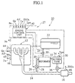
- the exhaust gas purification apparatus is used for purifying exhaust gases to be expelled to the atmosphere through an exhaust gas pipe 14, extending from an exhaust manifold of an engine 12, and a NOx trap catalyst device 16 located in the exhaust pipe 14 and serving as an exhaust gas purification device to trap NOx compounds.
- the exhaust gas purification apparatus 10 includes a reformer 20 which is supplied with a fuel and exhaust gases from a fuel tank 22 and the exhaust pipe 14 via a fuel supply conduit 24 and an exhaust gas supply branch conduit 26, respectively.
- the fuel tank 22 normally stores a hydrocarbon fuel such as gasoline or diesel fuel, which is also supplied to the engine 12 for propelling the same.
- the hydrocarbon fuel is mixed with air to provide an air/fuel mixture which is combusted in the engine 12 to produce a drive power output, with the exhaust gases being discharged to the atmosphere through the exhaust pipe 14 and the NOx trap catalyst device 16.
- the reformer 20 reforms fuel and exhaust gases into a reformed gas containing at least hydrogen which is used for reducing NOx compounds contained in the exhaust gases to thereby purify exhaust gases in the NOx trap catalyst device 16 in a manner as will be described below in detail.
- the exhaust gas purification apparatus 10 further includes a regulating section 27 composed of an exhaust gas flow control valve 28 and a fuel flow control valve 30, which are located in the branch conduit 26 and the fuel supply conduit 24, respectively, and an engine control unit 40.
- the exhaust gas flow control valve 28 is so constructed as to control the flow amount (introduction amount) of a part of the exhaust gases to be introduced into the reformer 20 in accordance with operating conditions of the engine 12 or the like in a manner as will be discussed below in detail and serves as an exhaust gas introduction amount adjustment means.
- the fuel flow control valve 30 is so constructed as to control the flow amount (supply amount) of fuel to be partly introduced into the reformer 20 in accordance with the operating conditions of the engine 12 or the like in a manner as will be discussed below in detail and serves as a fuel supply amount adjustment means.
- the reformed gas generated by the reformer 20 is fed through a reformed gas flow passage 32 into a buffer tank 34, from which a part of the reformed is fed through a reformed gas supply control valve 36 to the exhaust pipe 14 at a position downstream of a junction between the exhaust pipe 14 and the branch conduit 26, i.e. to an upstream side of the NOx trap catalyst device 16.
- the buffer tank 34 has a structure to temporarily accumulate the reformed gas in a given volume and serves as a reformed gas accumulation means.
- the NOx trap catalyst device 16 is connected to the exhaust pipe 14 at a position downstream of a junction between the exhaust pipe 14 and the reformed gas flow passage 32.
- the NOx trap catalyst device 16 is so constructed as to trap NOx compounds when an air/exhaust ratio remains in a lean side and to discharge the trapped NOx compounds for thereby purify the exhaust gases when an air/exhaust ratio remains in a theoretical air/exhaust ratio (stoichiometry) or in a rich side.
- Introduction of the reformed gas through the reformed gas supply control valve 36 into the NOx trap catalyst device 16 effectuates the reduction of the NOx compounds trapped in the NOx trap catalyst device 16 as controlled one.
- the reformer 20 is operated at the maximum performance by controlling the flow amounts of fuel and exhaust gases to be introduced into the reformer 20 and the flow amount of the reformed gas to be introduced into the NOx trap catalyst device 16, at desired values in dependence on operation state information of the engine 12.
- the engine control unit 40 is programmed to control the exhaust gas flow control valve 28, the fuel flow control valve 30 and the reformed gas supply control valve 36 in dependence on engine operation state information.
- the engine control unit 40 is connected to an engine speed sensor 42, an intake air amount sensor 44, an air/fuel ratio sensor 45, a cooling water temperature sensor 46, a trapped NOx amount sensor 48 and an accumulated reformed gas amount sensor 50 to receive an engine speed Ne, an intake air amount Qa, an air/fuel ratio A/F, a cooling water temperature Tw, a trapped NOx amount TNOx and an accumulated reformed gas amount Tgas from the above sensors, respectively, as engine operating parameters representing engine operation state information.
- the sensors 42, 44, 45 and 46 are attached to the engine 12, and the sensor 48 is attached to the NOx trap catalyst device 16 while the sensor 50 is attached to the buffer tank 34.
- the engine control unit 40 is programmed to be responsive to various engine operating parameters, which represent engine operation state information, to control an operation of the engine 12 and to control operations of the exhaust gas flow control valve 28, the fuel flow control valve 30 and the reformed gas supply control valve 36.
- the engine control unit 40 thus programmed controls the control valves 28, 30 and 36 according to calculated results of desired target flow amounts, with respective calculation methods being exemplified in control block diagrams shown in FIGS. 2A and 2B.
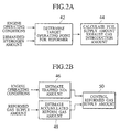
- FIG. 2A is a block diagram illustrating how the fuel supply amount and the exhaust gas introduction amount are calculated to achieve control of the fuel flow control valve 30 and the exhaust gas flow control valve 28, respectively.
- input parameters including operation state information of the engine 12 and a demanded hydrogen amount of the reformer 20 are applied to the engine control unit 40, which determines a target operating point for the reformer 20 in response to these input signals as indicated by the block 42.
- the engine control unit 40 calculates the fuel supply amount and the exhaust gas introduction amount for the reformer 20 on the basis of the target operating point for the reformer 20 as indicated by the block 44.
- FIG. 2B is a block diagram illustrating how the reformed gas supply amount is controlled by using the reformed gas supply control valve 36.
- input parameters including operation state information of the engine 12 and the reformed gas supply amount of the reformer 20 are applied to the engine control unit 40, which estimates a NOx trap rate, which is obtained by the NOx trap catalyst device 16, as indicted by the block 46 and the accumulated reformed gas amount of the buffer tank 34 in response to these input parameters as shown by the block 48.
- the engine control unit 40 is responsive to the estimated values of the trapped NOx amount and the accumulated reformed gas amount for controlling the reformed gas supply amount through the reformed gas supply control valve 36 as indicated by the block 50.
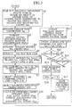
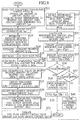
- FIG. 3 is a flow chart illustrating the basic sequence of operational steps of a control routine, which is repetitively executed for every given time period by a microcomputer of the engine control unit 40 in accordance with a program, for the exhaust gas purification apparatus to carry out an exhaust gas purification method according to the present invention.
- step S1 the microcomputer of the engine control unit 40 reads out the engine operating parameters involving the engine speed Ne, the intake air amount Qa, the air/fuel ratio A/F and the cooling water temperature Tw. Additionally, the microcomputer reads out the latest trapped NOx amount TNOx and the latest accumulated reformed gas amount Tgas which have been calculated by and stored in the latest control routine.
- step S2 the microcomputer estimates the exhaust gas temperature Tex in response to the engine operating parameters read out in step S1.
- the engine operating parameters (Ne, Qa, A/F, Tw) and the exhaust gas temperature Tex have characteristic relationships shown in the graphs shown in FIGS. 4A to 4D. More particularly, the exhaust gas temperature Tex and the engine speed Ne have the operating characteristic as shown in FIG. 4A. Further, the exhaust gas temperature Tex and the intake air amount Qa have the operating characteristic as shown in FIG. 4B. Furthermore, the exhaust gas temperature Tex and the air/fuel ratio A/F have the operating characteristic as shown in FIG. 4C. Also, the exhaust gas temperature Tex and the cooling water temperature Tw have the operating characteristic as shown in FIG. 4D.
- step S3 the microcomputer estimates an exhaust oxygen concentration PO2 and an exhaust moisture concentration PH2O, contained in the exhaust gases, on the basis of the air/fuel ratio A/F.
- the oxygen concentration degree PO2 and the water concentration PH2O have the characteristics varying in terms of the air/fuel ratio A/F as shown in FIGS. 5A and 5B. Therefore, the oxygen concentration PO2 and the moisture concentration PH2O can preferably be estimated from the air/fuel ratio A/F in the same technique as in step S2.
- step S4 the microcomputer estimates the amount ENOx of NOx content in the exhaust gases on the basis of the engine operating parameters (Ne, Qa, A/F, Tw).
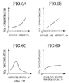
- the engine operating parameters (Ne, Qa, A/F, Tw) and the NOx concentration in the exhaust gases have characteristic relationships shown in the graphs shown in FIGS. 6A to 6D. More particularly, the NOx concentration and the engine speed Ne have the operating characteristic as shown in FIG. 6A. Further, the NOx concentration and the intake air amount Qa have the operating characteristic as shown in FIG. 6B. Furthermore, the NOx concentration and the air/fuel ratio A/F have the operating characteristic as shown in FIG. 6C. Also, the NOx concentration and the cooling water temperature Tw have the operating characteristic as shown in FIG.
- step S5 the microcomputer estimates the trapped NOx rate INOx of the NOx trap catalyst device 16.
- the trapped NOx rate INOx represents the rate of the NOx trapped in the NOx trap catalyst device 16 and varies according to the operating conditions of the NOx trap catalyst device 16 and the exhaust gas components. Typical examples are plotted in the graphs shown in FIGS. 7A to 7C.
- the trapped NOx rate INOx varies in terms of the trapped NOx amount TNOX as shown by a curve in FIG. 7A.
- the trapped NOx rate INOx varies in terms of the exhaust gas temperature Tex as plotted in a curve in FIG. 7B.
- the trapped NOx rate INOx varies in terms of the air/fuel ratio A/F as shown in a curve in FIG. 7C.
- the trapped NOx rate INOx can be estimated from the trapped NOx amount TNOx, the exhaust gas temperature Tex and the air/fuel ratio A/F in the same techniques as those in steps S2 to S4.
- step S6 the microcomputer substitutes this factor for an increment value dTNOx (dTNOx ⁇ ENOx ⁇ INOx).
- step S7 due to NOx trapping operation of the NOx trap catalyst device 16, since the trapped NOx amount TNOx increases by the increment value dTNOx, the increment value dTNOx of the trapped NOx amount is added to the latest trapped NOx amount TNOx, thereby updating the trapped NOx amount TNOx (TNOx ⁇ TNOx + dTNOx). It is to be noted here that steps S6 and S7 serve as the trapped NOx amount estimating means.
- the step S8 serves as a calculation means for calculating the demanded hydrogen amount.
- the symbol K refers to a hydrogen conversion value of NOx, i.e. the amount of hydrogen required for the reduction of the NOx per unit amount.
- a reformer operating characteristic map (i.e. a characteristic map of a hydrogen production amount in terms of the fuel supply amount and the exhaust gas introduction amount) is obtained from the exhaust gas temperature Tex and the air/fuel ratio A/F.
- Examples of the reformer operating characteristic maps are shown by graphs in FIGS. 8A to 8C wherein the fuel supply amounts are plotted in terms of the exhaust gas introduction amount and the reformed gas production amount in conjunction with the varying exhaust gas temperatures and the varying air/fuel ratios.
- the microcomputer selects the operating characteristic maps different from one another according to the exhaust gas temperature Tex and the air/fuel ratio A/F.
- the operating characteristic map of FIG. 8A is selected in a case when the exhaust gas temperature Tex remains at a low level and the air/fuel ratio A/F remains at a low level.
- the operating characteristic map of FIG. 8B is selected under a condition where the exhaust gas temperature Tex remain at a high level and the air/fuel ratio A/F remains at the low level.
- the operating characteristic map of FIG. 8C is selected under a condition where the exhaust gas temperature Tex remain at a high level and the air/fuel ratio A/F remains at a high level.
- such operating characteristic maps which serve as base references, respectively, may be corrected according to the above factors, thereby extracting corrected operating characteristic maps corresponding to these factors.
- the temperature detector means may be provided to detect the temperature of the reformer to generate a temperature detection signal, which is used in place of the exhaust gas temperature Tex when obtaining the operating characteristic maps. Further, in stead of employing the air/fuel ratio A/F, it may be possible for the operating characteristic maps to be obtained by using the oxygen concentration PO2 and the moisture concentration PH2O of the exhaust gases.
- step S10 the microcomputer determines the reformer's target operating point, i.e. the fuel supply amount dFfuel and the exhaust gas introduction amount dFexh, from the demanded hydrogen production amount dTH2 obtained in step S8, on the basis of the reformer operating characteristic maps obtained in step S9.
- the reformer's target operating point i.e. the fuel supply amount dFfuel and the exhaust gas introduction amount dFexh
- step S10 desired points, which satisfy the above factors, are obtained on the equivalent hydrogen production line representing the demanded hydrogen amount dTH2.
- FIGS. 8A to 8C show various graphs illustrating determined examples of the target operating points (i.e. the fuel supply amount dFfuel and the exhaust gas introduction amount dFexh) of the reformer in a case where given demanded hydrogen amount dTH2 under various operating conditions. Also, when determination for the target operating points has been completed, a current reformed gas amount dTgas is obtained from the operating characteristic maps.
- the target operating points i.e. the fuel supply amount dFfuel and the exhaust gas introduction amount dFexh
- step S11 the fuel flow control valve 30 and the exhaust gas flow control valve 28 are driven in response to the determined results (the fuel supply amount dFfuel and the exhaust gas introduction amount dFexh) obtained in step S10, thereby allowing the fuel and the exhaust gases to be supplied to the reformer 20 at respective controlled flow amounts.
- Steps S9 to S11 are implemented with the fuel flow control valve 30 and the exhaust gas flow control valve 28 to serve with these components as a fuel supply amount regulating means and an exhaust gas introduction amount regulating means.
- the reformer 30 Upon receipt of the fuel and exhaust gases, the reformer 30 generates the reformed gas which is temporarily accumulated in the buffer tank 34.
- step S12 the reformed gas amount dTgas which is currently generated is added to the latest accumulated reformed gas amount Tgas, thereby updating the accumulated reformed gas amount Tgas (Tgas ⁇ Tgas + dTgas).
- This step S12 serves as a reformed gas accumulation amount estimating means.
- the NOx trap catalyst device 16 since there is a limit in the amount of NOx to be trapped in the NOx trap catalyst device 16 and, if the amount of NOx exceeds the trapping capacity, the NOx compounds are exhausted to a downstream side of the NOx trap catalyst device 16, it is desirable for the NOx trap catalyst device 16 to be removed from the vehicle body and to be cleaned up prior to an increase of the NOx amount to an upper limit.
- step S13 the microcomputer discriminates whether the trapped NOx amount TNOx exceeds the upper limit TNOxMax or is below the same.
- the upper limit TNOxMax is referred to the trapped NOx amount that provides a difficulty in obtaining a given NOx trap rate.
- step S15 for opening the reformed gas supply control valve 36 to allow the reformed gas in the buffer tank 34 to be supplied to the exhaust pipe 14 at the upstream side of the NOx catalyst device 16, thereby allowing the trapped NOx in the NOx trap catalyst device 16 to be reduced and purified with hydrogen contained in the reformed gas.
- step S14 the operation goes to step S14 to implement another discrimination step. Since the volume of the buffer tank 34 is limited and the reformed gas exceeding the limited volume can not be accumulated. While, also, it is desired for the volume of the buffer tank 34 to be determined according to the max NOx amount necessary for execute the reduction at one time, there might be some instances where the hydrogen concentration is brought into a low level depending on the engine operating conditions to cause the reformed gas to increase in an excessive volume.
- step S14 the microcomputer discriminates whether the buffer tank 34 remains in an overflow state or in a normal state, i.e. whether the reformed gas accumulation amount Tgas exceeds the given upper limit value TgasMax corresponding to the volume of the buffer tank 34 or is below the same.
- step S15 for opening the reformed gas supply control valve 36 to allow the reformed gas in the buffer tank 34 to be supplied to the exhaust pipe 14 at the upstream side of the NOx catalyst device 16, thereby allowing the trapped NOx in the NOx trap catalyst device 16 to be reduced and purified with hydrogen contained in the reformed gas in a manner as previously described.
- steps S13 to S17 serve in combination with the reformed gas supply control valve 36 as a reformed gas supply control means.
- step S15 After opening the reformed gas supply control valve 36 in step S15 to discharge the reformed gas, the operation goes to step S16 for rendering the trapped NOx amount TNOx and the accumulated reformed gas amount Tgas to be cleared at "0", thereby completing the current routine.
- FIG. 9 is a flow chart illustrating the basic sequence of operation of a control routine of an exhaust gas purification apparatus of another embodiment of the present invention to carry out another method of the present invention, with like parts bearing the same reference numerals as those used in the apparatus of the embodiment shown in FIG. 1.
- Steps S21 to S27 are identical with steps S1 to S7 and, therefore, a detailed description of these steps is herein omitted for the sake of simplicity.
- step S21 the accumulated hydrogen amount TH2 of the buffer tank 34, which has been calculated and stored in the latest routine, is read out.
- step S28 the microcomputer calculates the demanded hydrogen amount dTH2 by adding the hydrogen amount of TNOx ⁇ K necessary for the reduction of the trapped NOx amount TNOx trapped in the NOx trap catalyst device 16 and the hydrogen amount of TO2 ⁇ L to be consumed by the oxygen TO2 contained in the exhaust gases when supplying the reformed gas to the exhaust pipe 14 to obtain the sum and by subsequently subtracting the accumulated hydrogen amount TH2 of the buffer tank 34 from the sum (dTH2 ⁇ TNOx ⁇ K + TO2 ⁇ L - TH2).
- Step S28 serves as a demanded hydrogen amount calculation means.
- the oxygen TO2 has a component such as oxygen contained in the exhaust gases and oxygen absorbed in a NOx trap catalyst of the device 16 and can be obtained on the basis of the air/fuel ratio A/F.
- the symbol L represents the hydrogen amount conversion value, i.e. the amount of hydrogen to be consumed by oxygen per unit amount.
- Step for obtaining the product of TO2 ⁇ L corresponds to a consumed hydrogen estimating means. Upon consideration of the product of TO2 ⁇ L in such a manner, it is possible to prevent the amount of hydrogen, required for reduction of the NOx compounds, from suffering a lack in volume.
- Steps S29 to S31 are identical to steps S9 to S11 of FIG. 3 and, therefore, a detailed description of the same is omitted.
- step S30 while the operation is executed to calculate the fuel supply amount dFfuel and the exhaust gas introduction amount dFexh to obtain the reformer's target operating point, calculation of the reformed gas amount dTgas is not implemented unlike step S10.
- step S32 the reformer's target operating point is obtained by detecting a real fuel supply amount dRFuel and a real exhaust gas introduction amount dRexh.
- step S33 further, the microcomputer calculates the reformed gas amount dTgas and the hydrogen production amount dTH2 on the basis of the real fuel supply amount dRfuel and the real exhaust gas introduction amount dRexh. Even with these steps, if it is difficult to obtain the flow amount with a target value because of the engine operating conditions and the operating characteristics of the control valves, etc., it is possible to detect the actual operating point, thereby rendering it possible to accurately obtain the reformed gas amount dTgas and the hydrogen production amount dTH2.
- Step S34 is identical with step S12 of FIG. 3 and a detailed description of the same is omitted.
- step S35 the microcomputer adds the hydrogen production amount dTH2 which is currently accumulated to the accumulated hydrogen TH2 of the buffer tank 34, thereby updating the accumulated hydrogen TH2 (TH2 ⁇ TH2 + dTH2).
- Step 35 corresponds to an accumulated hydrogen amount estimating means.
- step S39 the reformed gas supply control valve 36 is opened to allow the reformed gas in the buffer tank 34 to be discharged and, thereafter, the trapped NOx amount TNOx, the accumulated reformed gas amount Tgas and the accumulated hydrogen gas amount TH2 are cleared to "0".
- an important advantage of the exhaust gas purification apparatus and method of the present invention concerns a capability of regulating the fuel supply amount and the exhaust gas introduction amount in accordance with a demanded hydrogen amount and operating conditions of the internal combustion engine to allow the reformer to be operated at a maximum operating performance to enable supply of the reformed gas at the demanded flow amount.
- Another important advantage of the exhaust gas purification apparatus and method of the present invention concerns the fuel flow control valve, the exhaust gas flow control valve and the control unit programmed to control the fuel flow control valve and the exhaust gas flow control valve in dependence on the demanded hydrogen amount and the operating conditions of the engine to enable a reliable operation of the reformer in a simplified structure.
- Another important advantage of the exhaust gas purification apparatus and method of the present invention involves the use of the demanded hydrogen amount in combination with the temperature of the exhaust gases and the air/fuel ratio for regulating the fuel supply amount and the exhaust gas introduction amount to allow the reformer to be supplied with the fuel, the oxygen and the moisture at the flow amounts, necessary for the demanded hydrogen amount, in dependence on the various operating conditions of the engine.
- Another important advantage of the exhaust gas purification apparatus and method of the present invention involves the capability of regulating the fuel supply amount such that the fuel supply amount is decreased to the substantially minimum value in terms of the demanded hydrogen amount, thereby enabling a decreased fuel consumption in the reformer to prevent deterioration in a fuel economy.
- Another important advantage of the exhaust gas purification apparatus and method of the present invention involves the capability of regulating the amount of the reformed gas such that the amount of the reformed gas is decreased to the substantially minimum value in terms of the demanded hydrogen amount, i.e. to maximize the hydrogen concentration in the reformed gas. This allows the reformed gas to be generated at a high concentration with a decreased production amount, with a resultant decrease in the volume of the buffer tank that temporarily stores the reformed gas.
- Another important advantage of the exhaust gas purification apparatus and method of the present invention concerns the exhaust gas purifying device composed of the NOx trap catalyst device connected to the exhaust pipe to allow the reformed gas to be introduced into the exhaust gases at the position upstream of the catalyst at the desired flow amount for thereby increasing the purification performance of the reformer.
- Another important advantage of the exhaust gas purification apparatus and method of the present invention concerns the capability wherein the amount of NOx compounds trapped by the catalyst is estimated and the demanded hydrogen amount of the reformer is calculated on the basis of the estimated value of the amount of NOx compounds trapped by the catalyst for thereby enabling the reformer to generate the reformed gas containing the hydrogen with an amount required for the reduction of the NOx compounds.
- Another important advantage of the exhaust gas purification apparatus and method of the present invention involves the capability of calculating the demanded hydrogen amount according to the varying value of the amount of NOx compounds trapped by the catalyst, allowing the reformed gas to be temporarily stored in the buffer tank to enable storage of the hydrogen in the amount necessary for the reduction of the NOx compounds trapped in the catalyst at all times even when supplying the reformed gas into the exhaust system.
- Another important advantage of the exhaust gas purification apparatus and method of the present invention involves the capability of estimating the accumulated hydrogen gas amount of the reformed gas accumulation means to allow the demanded reformed gas amount to be calculated in dependence on the amount of NOx compounds trapped by the catalyst and the hydrogen accumulation amount of the reformed gas accumulation means, thereby enabling the demanded reformed gas to be suitably corrected on the basis of the trapped NOx compounds even in the presence of the difference between the demanded hydrogen amount required for the NOx reduction and the amount of the accumulated hydrogen.
- another important advantage of the exhaust gas purification apparatus and method of the present invention involves the capability of estimating the amount of hydrogen to be consumed by oxygen after supplying the reformed gas into the exhaust pipe and calculating the demanded hydrogen amount by adding the estimated amount of hydrogen to be consumed by the oxygen, thereby preventing a shortage of the amount of hydrogen required for the NOx reduction even when the hydrogen is consumed in reaction with the oxygen present in the exhaust gases.
- another important advantage of the exhaust gas purification apparatus and method of the present invention involves the capability of temporarily accumulating the reformed gas, estimating the reformed gas accumulation amount of the reformed gas accumulation means, and controlling the supply of the reformed gas into the exhaust pipe in dependence on the amount of NOx compounds trapped by the catalyst and the reformed gas accumulation amount of the reformed gas accumulation means, enabling the reformed gas to be supplied prior to the presence of the amount of trapped NOx compounds and the reformed gas accumulation amount increasing to the respective upper limits for thereby preventing a deterioration in the purification of the exhaust gases and in the operating performance of the purification device.
Abstract
Description
- The present invention relates to an exhaust gas purification apparatus and method and, more particularly, to an exhaust gas purification apparatus and method purifying exhaust gases exhausted from an internal combustion engine.
- As shown in Fig. 1 of SAE Paper 931096, it has been proposed to provide an exhaust gas purification apparatus having a reformer arranged to introduce a fuel and a part of exhaust gases of an internal combustion engine for reforming the same. The reformer is so constructed as to perform partial oxidation and steam reforming by using oxygen and water contained in the exhaust gases to generate a reformed gas containing hydrogen from a hydrocarbon fuel. The reformed gas has various applications such as a fuel for the internal combustion engine or a part of the fuel thereof, a reducing agent to be introduced into an exhaust system or a fuel for a combustor type heating device represented with a burner.
- However, in the use of such a reformer, various situations are encountered below in detail.
- First, it is required for the reformer to be operated so as to satisfy a demanded flow amount of the reformed gas which is determined according to intended purposes of the reformed gas and operating conditions of the internal combustion engine. This is due to the fact that a lack of the demanded flow amount of the reformed gas is reflected with a reduction in an effect obtained by the reformed gas whereas the presence of an excessive flow amount of the reformed gas is reflected in a waste of energy consumed by the reformer. Also, even with the provision of an accumulating tank that temporarily stores an excess amount of the reformed gas, the accumulating tank is required to have an increased volume in order to supply the reformed gas without shortage at all times, causing a difficulty in a design layout of the exhaust gas purification apparatus to be incorporated in a vehicle.
- Beside, it is considered that the temperature of the exhaust gases and the oxygen and moisture concentrations thereof may vary according to the operating conditions of the internal combustion engine, a variation in the operating performance of the reformer, a fluctuation in the amount of reformed gas and the hydrogen concentration. This results in a remarkable increase in the amount of fuel to generate the reformed gas at a given flow amount, causing an increased fuel consumption and fluctuation in the amount of the reformed gas to encounter a shortage in the amount of the reformed gas.
- The present invention has been made in view of the above studies and has an object to provide an exhaust gas purification apparatus and method which are able to operate a reformer at a high operating performance in accordance with operating conditions of an internal combustion engine so as to generate a reformed gas at a flow amount to satisfy a demanded amount of the reformed gas.
- According to one aspect of the present invention, there is provided an exhaust gas purification apparatus of an internal combustion engine. The internal combustion engine generates an exhaust gas to be introduced to an exhaust system thereof. The exhaust gas purification apparatus comprises: a reformer introducing a fuel and a part of the exhaust gas and generating a reformed gas including at least hydrogen; and a controller programmed to control a fuel supply amount of the fuel introduced to the reformer and an exhaust gas introduction amount of the exhaust gas introduced to the reformer in accordance with a demanded hydrogen amount of the reformer and operating conditions of the internal combustion engine. The exhaust gas is purified while controlling the fuel supply amount and the exhaust gas introduction amount.
- In other words, in the present invention, an exhaust gas purification apparatus of such an internal combustion engine comprises: reforming means for generating a reformed gas including at least hydrogen by introducing a fuel and a part of the exhaust gas; and controlling means for controlling a fuel supply amount of the fuel introduced to the reforming means and an exhaust gas introduction amount of the exhaust gas introduced to the reforming means in accordance with a demanded hydrogen amount of the reforming means and operating conditions of the internal combustion engine. The exhaust gas is purified, while controlling the fuel supply amount and the exhaust gas introduction amount.
- Besides, in the present invention, an exhaust gas purification method of such an internal combustion engine generates a reformed gas including at least hydrogen by introducing a fuel and a part of the exhaust gas, and controls a fuel supply amount of the fuel introduced when the reformed gas is generated and an exhaust gas introduction amount of the exhaust gas introduced when the reformed gas is generated in accordance with a demanded hydrogen amount demanded when the reformed gas is generated and operating conditions of the internal combustion engine. The exhaust gas is purified, while controlling the fuel supply amount and the exhaust gas introduction amount.
- Other and further features, advantages, and benefits of the present invention will become more apparent from the following description taken in conjunction with the following drawings.
-
- FIG. 1 is a schematic structural view of an exhaust gas purification apparatus of one embodiment according to the present invention;
- FIGS. 2A and 2B are block diagrams illustrating control routines for the exhaust gas purification apparatus shown in FIG. 1;
- FIG. 3 is a flow chart illustrating the basic sequence of operational steps for the exhaust gas purification apparatus shown in FIG. 1 to carry out a method of the present invention;
- FIGS. 4A to 4D are graphs illustrating characteristics for estimating the temperature of exhaust gases plotted in terms of operating parameters of an internal combustion engine of the apparatus shown FIG. 1;
- FIGS. 5A and 5B are graphs illustrating characteristics for estimating an oxygen concentration and a hydrogen concentration plotted in terms of the operating parameters of an internal combustion engine of the apparatus shown FIG. 1;
- FIGS. 6A to 6D are graphs illustrating characteristics for estimating a NOx concentration plotted in terms of the operating parameters of an internal combustion engine of the apparatus shown FIG. 1;
- FIGS. 7A to 7C are graphs illustrating characteristics for estimating a NOx trap rate plotted in terms of the operating parameters of an internal combustion engine of the apparatus shown FIG. 1;
- FIGS. 8A to 8C are graphs illustrating reformer's operating characteristics and examples for determining operating points in the exhaust gas purification apparatus shown in FIG. 1; and
- FIG. 9 is a flow chart illustrating the basic sequence of operational steps for an exhaust gas purification apparatus of another embodiment of the present invention to carry out a method of the present invention.
-
- To describe the present invention more in detail, an exhaust gas purification apparatus of several embodiments of the present invention to implement a method for purifying exhaust gases will be explained with reference to the accompanied drawings below.
- Referring to FIG. 1, there is shown an exhaust gas purification apparatus of an internal combustion engine (hereinafter referred to as an engine) of one embodiment according to the present invention. The exhaust gas purification apparatus, generally designated at 10, is used for purifying exhaust gases to be expelled to the atmosphere through an
exhaust gas pipe 14, extending from an exhaust manifold of anengine 12, and a NOxtrap catalyst device 16 located in theexhaust pipe 14 and serving as an exhaust gas purification device to trap NOx compounds. To this end, the exhaustgas purification apparatus 10 includes areformer 20 which is supplied with a fuel and exhaust gases from afuel tank 22 and theexhaust pipe 14 via afuel supply conduit 24 and an exhaust gassupply branch conduit 26, respectively. - The
fuel tank 22 normally stores a hydrocarbon fuel such as gasoline or diesel fuel, which is also supplied to theengine 12 for propelling the same. The hydrocarbon fuel is mixed with air to provide an air/fuel mixture which is combusted in theengine 12 to produce a drive power output, with the exhaust gases being discharged to the atmosphere through theexhaust pipe 14 and the NOxtrap catalyst device 16. - The
reformer 20 reforms fuel and exhaust gases into a reformed gas containing at least hydrogen which is used for reducing NOx compounds contained in the exhaust gases to thereby purify exhaust gases in the NOxtrap catalyst device 16 in a manner as will be described below in detail. - In order to operate the
reformer 20 at the maximum operating performance, the exhaustgas purification apparatus 10 further includes a regulatingsection 27 composed of an exhaust gasflow control valve 28 and a fuelflow control valve 30, which are located in thebranch conduit 26 and thefuel supply conduit 24, respectively, and anengine control unit 40. - The exhaust gas
flow control valve 28 is so constructed as to control the flow amount (introduction amount) of a part of the exhaust gases to be introduced into thereformer 20 in accordance with operating conditions of theengine 12 or the like in a manner as will be discussed below in detail and serves as an exhaust gas introduction amount adjustment means. Likewise, the fuelflow control valve 30 is so constructed as to control the flow amount (supply amount) of fuel to be partly introduced into thereformer 20 in accordance with the operating conditions of theengine 12 or the like in a manner as will be discussed below in detail and serves as a fuel supply amount adjustment means. - The reformed gas generated by the
reformer 20 is fed through a reformedgas flow passage 32 into abuffer tank 34, from which a part of the reformed is fed through a reformed gassupply control valve 36 to theexhaust pipe 14 at a position downstream of a junction between theexhaust pipe 14 and thebranch conduit 26, i.e. to an upstream side of the NOxtrap catalyst device 16. Thebuffer tank 34 has a structure to temporarily accumulate the reformed gas in a given volume and serves as a reformed gas accumulation means. - The NOx
trap catalyst device 16 is connected to theexhaust pipe 14 at a position downstream of a junction between theexhaust pipe 14 and the reformedgas flow passage 32. The NOxtrap catalyst device 16 is so constructed as to trap NOx compounds when an air/exhaust ratio remains in a lean side and to discharge the trapped NOx compounds for thereby purify the exhaust gases when an air/exhaust ratio remains in a theoretical air/exhaust ratio (stoichiometry) or in a rich side. Introduction of the reformed gas through the reformed gassupply control valve 36 into the NOxtrap catalyst device 16 effectuates the reduction of the NOx compounds trapped in the NOxtrap catalyst device 16 as controlled one. - With such a structure discussed above, the
reformer 20 is operated at the maximum performance by controlling the flow amounts of fuel and exhaust gases to be introduced into thereformer 20 and the flow amount of the reformed gas to be introduced into the NOxtrap catalyst device 16, at desired values in dependence on operation state information of theengine 12. - In order to achieve this end, the
engine control unit 40 is programmed to control the exhaust gasflow control valve 28, the fuelflow control valve 30 and the reformed gassupply control valve 36 in dependence on engine operation state information. - In particular, the
engine control unit 40 is connected to anengine speed sensor 42, an intakeair amount sensor 44, an air/fuel ratio sensor 45, a coolingwater temperature sensor 46, a trappedNOx amount sensor 48 and an accumulated reformedgas amount sensor 50 to receive an engine speed Ne, an intake air amount Qa, an air/fuel ratio A/F, a cooling water temperature Tw, a trapped NOx amount TNOx and an accumulated reformed gas amount Tgas from the above sensors, respectively, as engine operating parameters representing engine operation state information. Thesensors engine 12, and thesensor 48 is attached to the NOxtrap catalyst device 16 while thesensor 50 is attached to thebuffer tank 34. - The
engine control unit 40 is programmed to be responsive to various engine operating parameters, which represent engine operation state information, to control an operation of theengine 12 and to control operations of the exhaust gasflow control valve 28, the fuelflow control valve 30 and the reformed gassupply control valve 36. Theengine control unit 40 thus programmed controls thecontrol valves - FIG. 2A is a block diagram illustrating how the fuel supply amount and the exhaust gas introduction amount are calculated to achieve control of the fuel
flow control valve 30 and the exhaust gasflow control valve 28, respectively. As shown in FIG. 2A, input parameters including operation state information of theengine 12 and a demanded hydrogen amount of thereformer 20 are applied to theengine control unit 40, which determines a target operating point for thereformer 20 in response to these input signals as indicated by theblock 42. Further, theengine control unit 40 calculates the fuel supply amount and the exhaust gas introduction amount for thereformer 20 on the basis of the target operating point for thereformer 20 as indicated by theblock 44. - FIG. 2B is a block diagram illustrating how the reformed gas supply amount is controlled by using the reformed gas
supply control valve 36. As shown in FIG. 2B, input parameters including operation state information of theengine 12 and the reformed gas supply amount of thereformer 20 are applied to theengine control unit 40, which estimates a NOx trap rate, which is obtained by the NOxtrap catalyst device 16, as indicted by theblock 46 and the accumulated reformed gas amount of thebuffer tank 34 in response to these input parameters as shown by theblock 48. Further, theengine control unit 40 is responsive to the estimated values of the trapped NOx amount and the accumulated reformed gas amount for controlling the reformed gas supply amount through the reformed gassupply control valve 36 as indicated by theblock 50. - FIG. 3 is a flow chart illustrating the basic sequence of operational steps of a control routine, which is repetitively executed for every given time period by a microcomputer of the
engine control unit 40 in accordance with a program, for the exhaust gas purification apparatus to carry out an exhaust gas purification method according to the present invention. - First in step S1, the microcomputer of the
engine control unit 40 reads out the engine operating parameters involving the engine speed Ne, the intake air amount Qa, the air/fuel ratio A/F and the cooling water temperature Tw. Additionally, the microcomputer reads out the latest trapped NOx amount TNOx and the latest accumulated reformed gas amount Tgas which have been calculated by and stored in the latest control routine. - In step S2, the microcomputer estimates the exhaust gas temperature Tex in response to the engine operating parameters read out in step S1. In this connection, the engine operating parameters (Ne, Qa, A/F, Tw) and the exhaust gas temperature Tex have characteristic relationships shown in the graphs shown in FIGS. 4A to 4D. More particularly, the exhaust gas temperature Tex and the engine speed Ne have the operating characteristic as shown in FIG. 4A. Further, the exhaust gas temperature Tex and the intake air amount Qa have the operating characteristic as shown in FIG. 4B. Furthermore, the exhaust gas temperature Tex and the air/fuel ratio A/F have the operating characteristic as shown in FIG. 4C. Also, the exhaust gas temperature Tex and the cooling water temperature Tw have the operating characteristic as shown in FIG. 4D. These operating characteristics are processed to preliminarily form a matrix table or to form map data in the
engine control unit 40 to allow the operating characteristics to be referred to according to the values of the engine operating parameters. It will thus be seen that the exhaust gas temperature is readily estimated. Alternatively, an exhaust gas temperature sensor may be used to detect the exhaust gas temperature Tex in a direct fashion. - In step S3, the microcomputer estimates an exhaust oxygen concentration PO2 and an exhaust moisture concentration PH2O, contained in the exhaust gases, on the basis of the air/fuel ratio A/F. In this connection, the oxygen concentration degree PO2 and the water concentration PH2O have the characteristics varying in terms of the air/fuel ratio A/F as shown in FIGS. 5A and 5B. Therefore, the oxygen concentration PO2 and the moisture concentration PH2O can preferably be estimated from the air/fuel ratio A/F in the same technique as in step S2.
- In step S4, the microcomputer estimates the amount ENOx of NOx content in the exhaust gases on the basis of the engine operating parameters (Ne, Qa, A/F, Tw). In this connection, the engine operating parameters (Ne, Qa, A/F, Tw) and the NOx concentration in the exhaust gases have characteristic relationships shown in the graphs shown in FIGS. 6A to 6D. More particularly, the NOx concentration and the engine speed Ne have the operating characteristic as shown in FIG. 6A. Further, the NOx concentration and the intake air amount Qa have the operating characteristic as shown in FIG. 6B. Furthermore, the NOx concentration and the air/fuel ratio A/F have the operating characteristic as shown in FIG. 6C. Also, the NOx concentration and the cooling water temperature Tw have the operating characteristic as shown in FIG. 6D. These operating characteristics are processed to estimate the NOx concentration in the same technique as steps S2 and S3, with the NOx concentration being multiplied with the amount of exhaust gases to obtain the amount ENOx of the NOx concentration. While, also, the amount of exhaust gases may be obtained by calculating the intake air flow amount Qa and the air/fuel ratio A/F, the intake air amount Qa per se may be employed for a convenience.
- In step S5, the microcomputer estimates the trapped NOx rate INOx of the NOx
trap catalyst device 16. The trapped NOx rate INOx represents the rate of the NOx trapped in the NOxtrap catalyst device 16 and varies according to the operating conditions of the NOxtrap catalyst device 16 and the exhaust gas components. Typical examples are plotted in the graphs shown in FIGS. 7A to 7C. In particular, the trapped NOx rate INOx varies in terms of the trapped NOx amount TNOX as shown by a curve in FIG. 7A. Further, the trapped NOx rate INOx varies in terms of the exhaust gas temperature Tex as plotted in a curve in FIG. 7B. Likewise, the trapped NOx rate INOx varies in terms of the air/fuel ratio A/F as shown in a curve in FIG. 7C. Thus, the trapped NOx rate INOx can be estimated from the trapped NOx amount TNOx, the exhaust gas temperature Tex and the air/fuel ratio A/F in the same techniques as those in steps S2 to S4. Also, it may be possible to mount a detector means on the NOxtrap catalyst device 16 to directly detect the operating temperature thereof to allow the detected temperature to be used in place of the exhaust gas temperature Tex. - As to existing NOx amount ENOx in the exhaust gases, since the NOx amount to be trapped by the NOx
trap catalyst device 16 is represented by a formula ENOx × INOx, in step S6, the microcomputer substitutes this factor for an increment value dTNOx (dTNOx ← ENOx × INOx). - In step S7, due to NOx trapping operation of the NOx
trap catalyst device 16, since the trapped NOx amount TNOx increases by the increment value dTNOx, the increment value dTNOx of the trapped NOx amount is added to the latest trapped NOx amount TNOx, thereby updating the trapped NOx amount TNOx (TNOx ← TNOx + dTNOx). It is to be noted here that steps S6 and S7 serve as the trapped NOx amount estimating means. - In step S8, a demanded hydrogen amount dTH2, which represents the amount of hydrogen required for reduction of the incremental value dTNOx of the trapped NOx amount, is obtained as the product of the incremental value dTNOx of the trapped NOx amount and the coefficient K (dTH2 = dTNOx × K). Thus, the step S8 serves as a calculation means for calculating the demanded hydrogen amount. Here, the symbol K refers to a hydrogen conversion value of NOx, i.e. the amount of hydrogen required for the reduction of the NOx per unit amount. Thus, step S8 makes it possible to prepare the hydrogen gas at all times necessary for reduction of the trapped NOx.
- In step S9, a reformer operating characteristic map (i.e. a characteristic map of a hydrogen production amount in terms of the fuel supply amount and the exhaust gas introduction amount) is obtained from the exhaust gas temperature Tex and the air/fuel ratio A/F. Examples of the reformer operating characteristic maps are shown by graphs in FIGS. 8A to 8C wherein the fuel supply amounts are plotted in terms of the exhaust gas introduction amount and the reformed gas production amount in conjunction with the varying exhaust gas temperatures and the varying air/fuel ratios. As will be apparent from these graphs, since the reformer will operate under operating characteristics which are different from one another in dependence on the exhaust gas temperature Tex and the air/fuel ratio (i.e. the oxygen and water concentrations in the exhaust gases), in step S9, the microcomputer selects the operating characteristic maps different from one another according to the exhaust gas temperature Tex and the air/fuel ratio A/F.
- Among the examples of the operating characteristic maps shown in FIGS. 8A to 8C, the operating characteristic map of FIG. 8A is selected in a case when the exhaust gas temperature Tex remains at a low level and the air/fuel ratio A/F remains at a low level. The operating characteristic map of FIG. 8B is selected under a condition where the exhaust gas temperature Tex remain at a high level and the air/fuel ratio A/F remains at the low level. The operating characteristic map of FIG. 8C is selected under a condition where the exhaust gas temperature Tex remain at a high level and the air/fuel ratio A/F remains at a high level. In an alternative technology, such operating characteristic maps, which serve as base references, respectively, may be corrected according to the above factors, thereby extracting corrected operating characteristic maps corresponding to these factors. Also, the temperature detector means may be provided to detect the temperature of the reformer to generate a temperature detection signal, which is used in place of the exhaust gas temperature Tex when obtaining the operating characteristic maps. Further, in stead of employing the air/fuel ratio A/F, it may be possible for the operating characteristic maps to be obtained by using the oxygen concentration PO2 and the moisture concentration PH2O of the exhaust gases.
- In step S10, the microcomputer determines the reformer's target operating point, i.e. the fuel supply amount dFfuel and the exhaust gas introduction amount dFexh, from the demanded hydrogen production amount dTH2 obtained in step S8, on the basis of the reformer operating characteristic maps obtained in step S9.
- As seen from the reformer's operating characteristic maps shown in FIGS. 8A to 8C, although there are large number of combinations the fuel supply amount and the exhaust gas introduction amount appearing on an equivalent hydrogen production line in order to obtain a production of a certain amount of hydrogen, it is preferable to operate the engine at a low volume of fuel supply amount in view of minimizing fuel consumption. Also, it is preferable for the exhaust gas introduction amount (i.e. the volume of the reformed gas)to be maintained at a lower value to minimize the volume of the
buffer tank 34 in view of an overall layout of the exhaust gas purification apparatus to be mounted on a vehicle. - As a consequence, in step S10, desired points, which satisfy the above factors, are obtained on the equivalent hydrogen production line representing the demanded hydrogen amount dTH2. FIGS. 8A to 8C show various graphs illustrating determined examples of the target operating points (i.e. the fuel supply amount dFfuel and the exhaust gas introduction amount dFexh) of the reformer in a case where given demanded hydrogen amount dTH2 under various operating conditions. Also, when determination for the target operating points has been completed, a current reformed gas amount dTgas is obtained from the operating characteristic maps.
- In step S11, the fuel
flow control valve 30 and the exhaust gasflow control valve 28 are driven in response to the determined results (the fuel supply amount dFfuel and the exhaust gas introduction amount dFexh) obtained in step S10, thereby allowing the fuel and the exhaust gases to be supplied to thereformer 20 at respective controlled flow amounts. Steps S9 to S11 are implemented with the fuelflow control valve 30 and the exhaust gasflow control valve 28 to serve with these components as a fuel supply amount regulating means and an exhaust gas introduction amount regulating means. Upon receipt of the fuel and exhaust gases, thereformer 30 generates the reformed gas which is temporarily accumulated in thebuffer tank 34. - In step S12, the reformed gas amount dTgas which is currently generated is added to the latest accumulated reformed gas amount Tgas, thereby updating the accumulated reformed gas amount Tgas (Tgas ← Tgas + dTgas). This step S12 serves as a reformed gas accumulation amount estimating means.
- By the way, since there is a limit in the amount of NOx to be trapped in the NOx
trap catalyst device 16 and, if the amount of NOx exceeds the trapping capacity, the NOx compounds are exhausted to a downstream side of the NOxtrap catalyst device 16, it is desirable for the NOxtrap catalyst device 16 to be removed from the vehicle body and to be cleaned up prior to an increase of the NOx amount to an upper limit. - To achieve this end, in step S13, the microcomputer discriminates whether the trapped NOx amount TNOx exceeds the upper limit TNOxMax or is below the same. Here, the upper limit TNOxMax is referred to the trapped NOx amount that provides a difficulty in obtaining a given NOx trap rate.
- In case of "YES", the operation goes to step S15 for opening the reformed gas
supply control valve 36 to allow the reformed gas in thebuffer tank 34 to be supplied to theexhaust pipe 14 at the upstream side of theNOx catalyst device 16, thereby allowing the trapped NOx in the NOxtrap catalyst device 16 to be reduced and purified with hydrogen contained in the reformed gas. - On the contrary, in case of "NO", the operation goes to step S14 to implement another discrimination step. Since the volume of the
buffer tank 34 is limited and the reformed gas exceeding the limited volume can not be accumulated. While, also, it is desired for the volume of thebuffer tank 34 to be determined according to the max NOx amount necessary for execute the reduction at one time, there might be some instances where the hydrogen concentration is brought into a low level depending on the engine operating conditions to cause the reformed gas to increase in an excessive volume. - To address this issue, in step S14, the microcomputer discriminates whether the
buffer tank 34 remains in an overflow state or in a normal state, i.e. whether the reformed gas accumulation amount Tgas exceeds the given upper limit value TgasMax corresponding to the volume of thebuffer tank 34 or is below the same. - In case of "YES", the operation goes to step S15 for opening the reformed gas
supply control valve 36 to allow the reformed gas in thebuffer tank 34 to be supplied to theexhaust pipe 14 at the upstream side of theNOx catalyst device 16, thereby allowing the trapped NOx in the NOxtrap catalyst device 16 to be reduced and purified with hydrogen contained in the reformed gas in a manner as previously described. - On the contrary, in case of "NO", the operation goes to step S17 for rendering the reformed gas
supply control valve 36 in a closed state, thereby completing the current routine. Here, steps S13 to S17 serve in combination with the reformed gassupply control valve 36 as a reformed gas supply control means. - Also, after opening the reformed gas
supply control valve 36 in step S15 to discharge the reformed gas, the operation goes to step S16 for rendering the trapped NOx amount TNOx and the accumulated reformed gas amount Tgas to be cleared at "0", thereby completing the current routine. - FIG. 9 is a flow chart illustrating the basic sequence of operation of a control routine of an exhaust gas purification apparatus of another embodiment of the present invention to carry out another method of the present invention, with like parts bearing the same reference numerals as those used in the apparatus of the embodiment shown in FIG. 1.
- Steps S21 to S27 are identical with steps S1 to S7 and, therefore, a detailed description of these steps is herein omitted for the sake of simplicity. However, in step S21, the accumulated hydrogen amount TH2 of the
buffer tank 34, which has been calculated and stored in the latest routine, is read out. - In step S28, the microcomputer calculates the demanded hydrogen amount dTH2 by adding the hydrogen amount of TNOx × K necessary for the reduction of the trapped NOx amount TNOx trapped in the NOx
trap catalyst device 16 and the hydrogen amount of TO2 × L to be consumed by the oxygen TO2 contained in the exhaust gases when supplying the reformed gas to theexhaust pipe 14 to obtain the sum and by subsequently subtracting the accumulated hydrogen amount TH2 of thebuffer tank 34 from the sum (dTH2←TNOx × K + TO2 × L - TH2). Step S28 serves as a demanded hydrogen amount calculation means. Also, it seems that the oxygen TO2 has a component such as oxygen contained in the exhaust gases and oxygen absorbed in a NOx trap catalyst of thedevice 16 and can be obtained on the basis of the air/fuel ratio A/F. The symbol L represents the hydrogen amount conversion value, i.e. the amount of hydrogen to be consumed by oxygen per unit amount. Step for obtaining the product of TO2 × L corresponds to a consumed hydrogen estimating means. Upon consideration of the product of TO2 × L in such a manner, it is possible to prevent the amount of hydrogen, required for reduction of the NOx compounds, from suffering a lack in volume. - Steps S29 to S31 are identical to steps S9 to S11 of FIG. 3 and, therefore, a detailed description of the same is omitted. However, in step S30, while the operation is executed to calculate the fuel supply amount dFfuel and the exhaust gas introduction amount dFexh to obtain the reformer's target operating point, calculation of the reformed gas amount dTgas is not implemented unlike step S10.
- In step S32, the reformer's target operating point is obtained by detecting a real fuel supply amount dRFuel and a real exhaust gas introduction amount dRexh. In consecutive step S33, further, the microcomputer calculates the reformed gas amount dTgas and the hydrogen production amount dTH2 on the basis of the real fuel supply amount dRfuel and the real exhaust gas introduction amount dRexh. Even with these steps, if it is difficult to obtain the flow amount with a target value because of the engine operating conditions and the operating characteristics of the control valves, etc., it is possible to detect the actual operating point, thereby rendering it possible to accurately obtain the reformed gas amount dTgas and the hydrogen production amount dTH2.
- Step S34 is identical with step S12 of FIG. 3 and a detailed description of the same is omitted.
- In step S35, the microcomputer adds the hydrogen production amount dTH2 which is currently accumulated to the accumulated hydrogen TH2 of the
buffer tank 34, thereby updating the accumulated hydrogen TH2 (TH2 ← TH2 + dTH2). Step 35 corresponds to an accumulated hydrogen amount estimating means. - Subsequent steps S36 to S40 are identical as steps S13 to S17 and a detailed description of the same is herein omitted. However, in step S39, the reformed gas
supply control valve 36 is opened to allow the reformed gas in thebuffer tank 34 to be discharged and, thereafter, the trapped NOx amount TNOx, the accumulated reformed gas amount Tgas and the accumulated hydrogen gas amount TH2 are cleared to "0". - With such a structure of the present embodiment, even in a case where the
reformer 20 can not perform the operation at an intended target, such a phenomenon can be effectively considered in the demanded hydrogen amount during subsequent computation of the various factors to provide a corrected value, for thereby minimizing the overshooting or undershooting phenomenon of the hydrogen production amount. - It will now be understood from the foregoing embodiments of the present invention, an important advantage of the exhaust gas purification apparatus and method of the present invention concerns a capability of regulating the fuel supply amount and the exhaust gas introduction amount in accordance with a demanded hydrogen amount and operating conditions of the internal combustion engine to allow the reformer to be operated at a maximum operating performance to enable supply of the reformed gas at the demanded flow amount.
- Another important advantage of the exhaust gas purification apparatus and method of the present invention concerns the fuel flow control valve, the exhaust gas flow control valve and the control unit programmed to control the fuel flow control valve and the exhaust gas flow control valve in dependence on the demanded hydrogen amount and the operating conditions of the engine to enable a reliable operation of the reformer in a simplified structure.
- Another important advantage of the exhaust gas purification apparatus and method of the present invention involves the use of the demanded hydrogen amount in combination with the temperature of the exhaust gases and the air/fuel ratio for regulating the fuel supply amount and the exhaust gas introduction amount to allow the reformer to be supplied with the fuel, the oxygen and the moisture at the flow amounts, necessary for the demanded hydrogen amount, in dependence on the various operating conditions of the engine.
- Another important advantage of the exhaust gas purification apparatus and method of the present invention involves the capability of regulating the fuel supply amount such that the fuel supply amount is decreased to the substantially minimum value in terms of the demanded hydrogen amount, thereby enabling a decreased fuel consumption in the reformer to prevent deterioration in a fuel economy.
- Another important advantage of the exhaust gas purification apparatus and method of the present invention involves the capability of regulating the amount of the reformed gas such that the amount of the reformed gas is decreased to the substantially minimum value in terms of the demanded hydrogen amount, i.e. to maximize the hydrogen concentration in the reformed gas. This allows the reformed gas to be generated at a high concentration with a decreased production amount, with a resultant decrease in the volume of the buffer tank that temporarily stores the reformed gas.
- Another important advantage of the exhaust gas purification apparatus and method of the present invention concerns the exhaust gas purifying device composed of the NOx trap catalyst device connected to the exhaust pipe to allow the reformed gas to be introduced into the exhaust gases at the position upstream of the catalyst at the desired flow amount for thereby increasing the purification performance of the reformer.
- Another important advantage of the exhaust gas purification apparatus and method of the present invention concerns the capability wherein the amount of NOx compounds trapped by the catalyst is estimated and the demanded hydrogen amount of the reformer is calculated on the basis of the estimated value of the amount of NOx compounds trapped by the catalyst for thereby enabling the reformer to generate the reformed gas containing the hydrogen with an amount required for the reduction of the NOx compounds.
- Another important advantage of the exhaust gas purification apparatus and method of the present invention involves the capability of calculating the demanded hydrogen amount according to the varying value of the amount of NOx compounds trapped by the catalyst, allowing the reformed gas to be temporarily stored in the buffer tank to enable storage of the hydrogen in the amount necessary for the reduction of the NOx compounds trapped in the catalyst at all times even when supplying the reformed gas into the exhaust system.
- Another important advantage of the exhaust gas purification apparatus and method of the present invention involves the capability of estimating the accumulated hydrogen gas amount of the reformed gas accumulation means to allow the demanded reformed gas amount to be calculated in dependence on the amount of NOx compounds trapped by the catalyst and the hydrogen accumulation amount of the reformed gas accumulation means, thereby enabling the demanded reformed gas to be suitably corrected on the basis of the trapped NOx compounds even in the presence of the difference between the demanded hydrogen amount required for the NOx reduction and the amount of the accumulated hydrogen.
- Also, another important advantage of the exhaust gas purification apparatus and method of the present invention involves the capability of estimating the amount of hydrogen to be consumed by oxygen after supplying the reformed gas into the exhaust pipe and calculating the demanded hydrogen amount by adding the estimated amount of hydrogen to be consumed by the oxygen, thereby preventing a shortage of the amount of hydrogen required for the NOx reduction even when the hydrogen is consumed in reaction with the oxygen present in the exhaust gases.
- Still also, another important advantage of the exhaust gas purification apparatus and method of the present invention involves the capability of temporarily accumulating the reformed gas, estimating the reformed gas accumulation amount of the reformed gas accumulation means, and controlling the supply of the reformed gas into the exhaust pipe in dependence on the amount of NOx compounds trapped by the catalyst and the reformed gas accumulation amount of the reformed gas accumulation means, enabling the reformed gas to be supplied prior to the presence of the amount of trapped NOx compounds and the reformed gas accumulation amount increasing to the respective upper limits for thereby preventing a deterioration in the purification of the exhaust gases and in the operating performance of the purification device.
- The entire content of a Patent Application No. TOKUGAN 2000-365234 with a filing date of November 30, 2000 in Japan is hereby incorporated by reference.
- Although the invention has been described above by reference to certain embodiments of the invention, the invention is not limited to the embodiments described above. Modifications and variations of the embodiments described above will occur to those skilled in the art, in light of the teachings. The scope of the invention is defined with reference to the following claims.
Claims (13)
- An exhaust gas purification apparatus of an internal combustion engine (12), the internal combustion engine generating an exhaust gas to be introduced to an exhaust system (14) thereof, comprising:wherein the exhaust gas is purified while controlling the fuel supply amount and the exhaust gas introduction amount.a reformer (20) introducing a fuel and a part of the exhaust gas and generating a reformed gas including at least hydrogen; anda controller (40) programmed to control a fuel supply amount of the fuel introduced to the reformer and an exhaust gas introduction amount of the exhaust gas introduced to the reformer in accordance with a demanded hydrogen amount of the reformer and operating conditions of the internal combustion engine,
- An exhaust gas purification apparatus according to claim 1, wherein the operating conditions of the internal combustion engine (12) include an exhaust gas temperature of the internal combustion engine and an air/fuel ratio of the internal combustion engine as engine operating parameters.
- An exhaust gas purification apparatus according to claim 1 or 2, further comprising:wherein the controller (40) controls the fuel supply amount and the exhaust gas introduction amount through the fuel flow control valve and the exhaust gas flow control valve in accordance with the demanded hydrogen amount, the exhaust gas temperature and the air/fuel ratio.a fuel flow control valve (30) regulating the fuel supply amount; andan exhaust gas flow control valve (28) regulating the exhaust gas introduction amount,
- An exhaust gas purification apparatus according to any of claims 1 to 3, wherein the controller (40) is operative to control the fuel supply amount such that the fuel supply amount is decreased to a substantially minimum value with respect to the demanded hydrogen amount.
- An exhaust gas purification apparatus according to any of claims 1 to 3, wherein the controller (40) is operative to control an amount of the reformed gas generated by the reformer such that the amount of the reformed gas is decreased to a substantially minimum value with respect to the demanded hydrogen amount.
- An exhaust gas purification apparatus according to any of claims 1 to 3, wherein a NOx trap catalyst device (16) is provided to the exhaust system (14) to have an operating property which traps NOx compounds contained in the exhaust gas during a lean condition of the air/fuel ratio of the exhaust gas and discharges trapped NOx compounds during a stoichiometry condition of the air/fuel ratio or during a rich condition of the air/fuel ratio,
and wherein the reformed gas is supplied to an upstream of the NOx trap catalyst device. - An exhaust gas purification apparatus according to claim 6, wherein the controller (40) estimates an amount of the NOx compounds trapped by the NOx trap catalyst device (16) and calculates the demanded hydrogen amount in accordance with the amount of the NOx compounds trapped by the NOx trap catalyst device.
- An exhaust gas purification apparatus according to claim 6, wherein the controller (40) calculates the demanded hydrogen amount in accordance with a varying value of the amount of the NOx compounds trapped by the NOx trap catalyst device (16).
- An exhaust gas purification apparatus according to claim 6, further comprising an accumulation device (34) temporarily accumulating the reformed gas,
wherein the controller (40) estimates an amount of the hydrogen accumulated by the accumulation device and calculates the demanded hydrogen amount in accordance with the amount of the NOx compounds trapped by the NOx trap catalyst device (16) and the amount of the hydrogen accumulated by the accumulation device. - An exhaust gas purification apparatus according to claim 6, wherein the controller (40) estimates an amount of the hydrogen consumed by oxygen after supplying the reformed gas into the exhaust system (14) and calculates the demanded hydrogen amount by adding the amount of the hydrogen consumed by the oxygen.
- An exhaust gas purification apparatus according to claim 6, further comprising an accumulation device (34) temporarily accumulating the reformed gas,
wherein the controller (40) estimates an amount of the reformed gas accumulated by the accumulation device and controls to supply the reformed gas to the upstream of the NOx trap catalyst device (16) in accordance with the amount of the NOx compounds trapped by the NOx trap catalyst device and the amount of the reformed gas accumulated by the accumulation device. - An exhaust gas purification apparatus of an internal combustion engine (12), the internal combustion engine generating an exhaust gas to be introduced to an exhaust system (14) thereof, comprising:wherein the exhaust gas is purified, while controlling the fuel supply amount and the exhaust gas introduction amount.reforming means (20) for generating a reformed gas including at least hydrogen by introducing a fuel and a part of the exhaust gas; andcontrolling means (40) for controlling a fuel supply amount of the fuel introduced to the reforming means and an exhaust gas introduction amount of the exhaust gas introduced to the reforming means in accordance with a demanded hydrogen amount of the reforming means and operating conditions of the internal combustion engine,
- An exhaust gas purification method of an internal combustion engine, the internal combustion engine (12) generating an exhaust gas to be introduced to an exhaust system (14) thereof, comprising:wherein the exhaust gas is purified, while controlling the fuel supply amount and the exhaust gas introduction amount.generating a reformed gas including at least hydrogen by introducing a fuel and a part of the exhaust gas; andcontrolling a fuel supply amount of the fuel introduced when the reformed gas is generated and an exhaust gas introduction amount of the exhaust gas introduced when the reformed gas is generated in accordance with a demanded hydrogen amount demanded when the reformed gas is generated and operating conditions of the internal combustion engine,
Applications Claiming Priority (2)
| Application Number | Priority Date | Filing Date | Title |
|---|---|---|---|
| JP2000365234 | 2000-11-30 | ||
| JP2000365234A JP3685052B2 (en) | 2000-11-30 | 2000-11-30 | Exhaust gas purification device for internal combustion engine |
Publications (3)
| Publication Number | Publication Date |
|---|---|
| EP1211394A2 true EP1211394A2 (en) | 2002-06-05 |
| EP1211394A3 EP1211394A3 (en) | 2003-01-08 |
| EP1211394B1 EP1211394B1 (en) | 2005-09-07 |
Family
ID=18836045
Family Applications (1)
| Application Number | Title | Priority Date | Filing Date |
|---|---|---|---|
| EP01128070A Expired - Lifetime EP1211394B1 (en) | 2000-11-30 | 2001-11-26 | Exhaust gas purification apparatus and method |
Country Status (4)
| Country | Link |
|---|---|
| US (1) | US6845610B2 (en) |
| EP (1) | EP1211394B1 (en) |
| JP (1) | JP3685052B2 (en) |
| DE (1) | DE60113224T2 (en) |
Cited By (27)
| Publication number | Priority date | Publication date | Assignee | Title |
|---|---|---|---|---|
| WO2003048536A1 (en) * | 2001-12-03 | 2003-06-12 | Catalytica Energy Systems, Inc. | System and methods for improved emission control of internal combustion engines |
| DE10161696A1 (en) * | 2001-12-15 | 2003-06-26 | Bayerische Motoren Werke Ag | Process for the catalytic exhaust aftertreatment of engine combustion exhaust gases |
| WO2004046514A1 (en) * | 2002-11-15 | 2004-06-03 | Catalytica Energy Systems, Inc. | Devices and methods for reduction of nox emissions from lean burn engines |
| FR2849468A1 (en) * | 2002-12-30 | 2004-07-02 | Renault Sa | Pollution reduction system for vehicle IC engine with catalytic oxidizer incorporates reformer to produce hydrogen-based gas mixture from fuel in tank |
| WO2004090296A1 (en) * | 2003-04-05 | 2004-10-21 | Daimlerchrysler Ag | Device and method for exhaust gas aftertreatment |
| WO2004101965A1 (en) * | 2003-05-06 | 2004-11-25 | Catalytica Energy Systems, Inc. | System and methods for improved emission control of internal combustion engines using pulsed fuel flow |
| EP1484103A1 (en) * | 2003-06-06 | 2004-12-08 | Umicore AG & Co. KG | Process and apparatus for catalytic conversion of hydrocarbons for generating a gas rich in hydrogen |
| DE102004051121A1 (en) * | 2003-10-21 | 2005-06-02 | Toyota Jidosha K.K., Toyota | Internal combustion engine |
| WO2005054636A2 (en) * | 2003-12-06 | 2005-06-16 | Daimlerchrysler Ag | Exhaust gas purification system for a motor vehicle comprising a reducing agent storage vessel and operating method therefor |
| DE10120097B4 (en) * | 2001-04-25 | 2005-07-21 | Daimlerchrysler Ag | Emission control system and method for operating the system |
| WO2006008625A1 (en) * | 2004-07-14 | 2006-01-26 | Eaton Corporation | Hybrid catalyst system for exhaust emissions reduction |
| WO2006010277A2 (en) * | 2004-07-29 | 2006-02-02 | Nxtgen Emission Controls Inc. | Integrated system for reducing fuel consumption and emissions in an internal combustion engine |
| EP1702142A2 (en) * | 2003-10-23 | 2006-09-20 | HydrogenSource LLC | Intermittent application of syngas to nox trap and/or diesel engine |
| DE102005025455A1 (en) * | 2005-06-02 | 2006-12-07 | Webasto Ag | Exhaust gas e.g. nitrogen oxides, cleaning device for internal combustion engine e.g. diesel engine, has supplying device comprising reformer, which converts exhaust gas and fuel from engine into reformate that serves as reducing agent |
| US7155331B1 (en) | 2003-12-15 | 2006-12-26 | Donaldson Company, Inc. | Method of prediction of NOx mass flow in exhaust |
| WO2007020035A1 (en) * | 2005-08-12 | 2007-02-22 | Universität (Th) Karlsruhe | Device for the selective nox reduction in nox containing exhaust gases |
| FR2900196A1 (en) * | 2006-04-25 | 2007-10-26 | Renault Sas | Exhaust gas treating installation controlling method for e.g. oil engine of motor vehicle, involves controlling reformer with reformate setting rate based on space coefficient and calculated reformate rate |
| EP1925790A1 (en) * | 2006-11-17 | 2008-05-28 | J. Eberspächer GmbH & Co. KG | System of an internal combustion engine |
| WO2008101334A1 (en) * | 2007-02-19 | 2008-08-28 | Nxtgen Emission Controls Inc. | Method of operating a syngas generator |
| WO2009070383A1 (en) * | 2007-11-30 | 2009-06-04 | General Electric Company | Methods for reducing emissions from diesel engines |
| US7593788B2 (en) | 2003-04-04 | 2009-09-22 | Texaco Inc. | Automated control strategy for fuel processor reactor shift catalyst regeneration |
| EP2248764A1 (en) * | 2008-02-20 | 2010-11-10 | Honda Motor Co., Ltd. | Fuel reforming device |
| US8006484B2 (en) | 2005-02-14 | 2011-08-30 | Eaton Corporation | Systems and methods for reducing emissions of internal combustion engines using a fuel processor bypass |
| US8056322B2 (en) | 2005-12-12 | 2011-11-15 | General Electric Company | System and method for supplying oxygenate reductants to an emission treatment system |
| EP1640580B1 (en) * | 2004-09-27 | 2012-04-04 | Toyota Jidosha Kabushiki Kaisha | Fuel reforming method and fuel reforming device of internal combustion engine |
| DE102014202291A1 (en) * | 2014-02-07 | 2015-08-13 | Volkswagen Aktiengesellschaft | Exhaust gas purification device and motor vehicle with such |
| CN106837619A (en) * | 2017-01-06 | 2017-06-13 | 天津大学 | Combine the new type low temperature apparatus for reforming of fuel of external reformer based on engine |
Families Citing this family (42)
| Publication number | Priority date | Publication date | Assignee | Title |
|---|---|---|---|---|
| US6895746B2 (en) | 2002-05-31 | 2005-05-24 | Utc Fuel Cells, Llc | Reducing oxides of nitrogen using hydrogen generated from engine fuel and exhaust |
| US20030226350A1 (en) * | 2002-06-11 | 2003-12-11 | Ke Liu | Reducing oxides of nitrogen using reformate generated from engine fuel, water and/or air |
| US6651623B1 (en) * | 2002-08-01 | 2003-11-25 | Ford Global Technologies, Llc | Method and system for measuring air/fuel ratio in a hydrogen fueled internal combustion engine |
| CA2406386C (en) * | 2002-10-02 | 2004-05-18 | Westport Research Inc. | Method and apparatus for regenerating nox adsorbers |
| US7040084B2 (en) * | 2002-12-16 | 2006-05-09 | General Motors Corporation | Exhaust emission aftertreatment |
| DE10305057A1 (en) * | 2003-02-07 | 2004-08-19 | Daimlerchrysler Ag | Exhaust after-treatment system and commercial vehicle with exhaust aftertreatment system |
| US20050193724A1 (en) * | 2004-02-27 | 2005-09-08 | Southwest Research Institute | Oxygen-enriched feedgas for reformer in emissions control system |
| JP4506335B2 (en) * | 2004-07-28 | 2010-07-21 | トヨタ自動車株式会社 | Internal combustion engine and operation control device for internal combustion engine |
| US20060242906A1 (en) * | 2005-04-28 | 2006-11-02 | Macbain John A | Reformer system and method of operating the same |
| US7776280B2 (en) * | 2005-05-10 | 2010-08-17 | Emcon Technologies Llc | Method and apparatus for selective catalytic reduction of NOx |
| JP2006322399A (en) * | 2005-05-19 | 2006-11-30 | Toyota Motor Corp | Exhaust emission control device for internal combustion engine |
| JP5136905B2 (en) * | 2005-06-22 | 2013-02-06 | イートン コーポレーション | Method for producing hydrogen from hydrocarbon fuels |
| US7788906B2 (en) * | 2005-07-27 | 2010-09-07 | Eaton Corporation | Methods and systems for controlling internal combustion engines |
| US20070033929A1 (en) * | 2005-08-11 | 2007-02-15 | Arvinmeritor Emissions Technologies Gmbh | Apparatus with in situ fuel reformer and associated method |
| US7216481B2 (en) * | 2005-09-23 | 2007-05-15 | Delphi Technologies, Inc. | Method and apparatus for regeneration of engine exhaust aftertreatment devices |
| JP4559363B2 (en) * | 2006-01-12 | 2010-10-06 | 株式会社日立製作所 | Gas turbine equipped with heavy oil reformer, control device for heavy oil reformer, and operation method of gas turbine equipped with heavy oil reformer |
| US7293409B2 (en) * | 2006-02-07 | 2007-11-13 | Delphi Technologies, Inc. | Process and system for improving combustion and exhaust aftertreatment of motor vehicle engines |
| JP2007278162A (en) * | 2006-04-06 | 2007-10-25 | Hino Motors Ltd | Exhaust emission control device for diesel engine |
| US20070289291A1 (en) * | 2006-06-14 | 2007-12-20 | Alexander Rabinovich | Apparatus and Method for NOx Reduction |
| US20080020333A1 (en) * | 2006-06-14 | 2008-01-24 | Smaling Rudolf M | Dual reaction zone fuel reformer and associated method |
| JP4901816B2 (en) * | 2008-06-30 | 2012-03-21 | 株式会社日立製作所 | Engine system with reformer |
| US7767181B2 (en) * | 2006-06-30 | 2010-08-03 | Caterpillar Inc | System and method for ammonia production |
| US20080141662A1 (en) * | 2006-12-14 | 2008-06-19 | Markus Schuster | Fluid injecting and mixing systems for exhaust after-treatment devices |
| US8926720B2 (en) * | 2007-05-01 | 2015-01-06 | Westport Power Inc. | Control system and method for a fuel processor |
| US20100018476A1 (en) * | 2007-05-31 | 2010-01-28 | Svetlana Mikhailovna Zemskova | On-board hydrogen generator |
| JP2009162053A (en) * | 2007-11-14 | 2009-07-23 | Toyota Motor Corp | Control device for internal combustion engine |
| JP2009162157A (en) * | 2008-01-08 | 2009-07-23 | Honda Motor Co Ltd | Exhaust emission control device for internal combustion engine |
| US20090173058A1 (en) * | 2008-01-09 | 2009-07-09 | General Electric Company | System and method for the on-board production of reductants |
| JP4837694B2 (en) * | 2008-03-12 | 2011-12-14 | 本田技研工業株式会社 | Control device for internal combustion engine |
| JP5115328B2 (en) * | 2008-05-20 | 2013-01-09 | トヨタ自動車株式会社 | Internal combustion engine |
| US20100024400A1 (en) * | 2008-08-01 | 2010-02-04 | General Electric Company | Emission control system and method |
| JP5307899B2 (en) * | 2009-09-30 | 2013-10-02 | 株式会社日立製作所 | Engine system with reformer |
| GB2485362A (en) * | 2010-11-11 | 2012-05-16 | Johnson Matthey Plc | Gasoline engine exhaust manifold comprising a reforming catalyst |
| WO2012107949A1 (en) * | 2011-02-07 | 2012-08-16 | トヨタ自動車株式会社 | Internal combustion engine |
| JP5966377B2 (en) * | 2012-01-20 | 2016-08-10 | 日産自動車株式会社 | Control device for internal combustion engine |
| US9440851B2 (en) | 2012-05-23 | 2016-09-13 | Herng Shinn Hwang | Flex-fuel hydrogen generator for IC engines and gas turbines |
| US10865709B2 (en) | 2012-05-23 | 2020-12-15 | Herng Shinn Hwang | Flex-fuel hydrogen reformer for IC engines and gas turbines |
| JP5680169B1 (en) * | 2013-10-25 | 2015-03-04 | 三菱電機株式会社 | Control device and control method for internal combustion engine |
| JP2016130186A (en) * | 2015-01-13 | 2016-07-21 | 株式会社デンソー | Fuel reformer |
| JP5963927B1 (en) * | 2015-08-21 | 2016-08-03 | 三菱電機株式会社 | Control device and method for internal combustion engine with supercharger |
| US10626790B2 (en) | 2016-11-16 | 2020-04-21 | Herng Shinn Hwang | Catalytic biogas combined heat and power generator |
| US11035315B2 (en) * | 2019-09-27 | 2021-06-15 | Ford Global Technologies, Llc | Modeling to compensate for HEGO sensor drift |
Family Cites Families (18)
| Publication number | Priority date | Publication date | Assignee | Title |
|---|---|---|---|---|
| DE2410644A1 (en) * | 1974-03-06 | 1975-09-18 | Reinhold Dipl Ing Schmidt | ARRANGEMENTS ON COMBUSTION MACHINES AND / OR FIRING SYSTEMS AT METHANOL OPERATION |
| JPS6368714A (en) | 1986-09-10 | 1988-03-28 | Mazda Motor Corp | Exhaust emission control device for engine |
| US5201802A (en) * | 1991-02-04 | 1993-04-13 | Toyota Jidosha Kabushiki Kaisha | Exhaust gas purification system for an internal combustion engine |
| US5272871A (en) * | 1991-05-24 | 1993-12-28 | Kabushiki Kaisha Toyota Chuo Kenkyusho | Method and apparatus for reducing nitrogen oxides from internal combustion engine |
| JPH05106430A (en) * | 1991-10-16 | 1993-04-27 | Toyota Central Res & Dev Lab Inc | Nitrogen oxide reducing device for internal combustion engine |
| JPH06117224A (en) * | 1992-09-30 | 1994-04-26 | Mitsubishi Motors Corp | Exhaust emission control device |
| JPH06137138A (en) * | 1992-10-28 | 1994-05-17 | Mitsubishi Motors Corp | Exhaust gas purifying device |
| DE4404617C2 (en) * | 1994-02-14 | 1998-11-05 | Daimler Benz Ag | Device for the selective catalyzed NO¶x¶ reduction in oxygen-containing exhaust gases from internal combustion engines |
| US5522218A (en) * | 1994-08-23 | 1996-06-04 | Caterpillar Inc. | Combustion exhaust purification system and method |
| JPH0913955A (en) * | 1995-06-27 | 1997-01-14 | Komatsu Ltd | Exhaust gas purifying device for diesel engine |
| US5921076A (en) | 1996-01-09 | 1999-07-13 | Daimler-Benz Ag | Process and apparatus for reducing nitrogen oxides in engine emissions |
| JPH1089057A (en) * | 1996-09-18 | 1998-04-07 | Mitsubishi Motors Corp | Exhaust emission control device of engine |
| US5809774A (en) * | 1996-11-19 | 1998-09-22 | Clean Diesel Technologies, Inc. | System for fueling and feeding chemicals to internal combustion engines for NOx reduction |
| SE509787C2 (en) | 1997-07-18 | 1999-03-08 | Volvo Ab | Device and process for catalytic exhaust gas purification with hydrogen supply |
| DE19755600C2 (en) * | 1997-12-15 | 2002-01-17 | Bosch Gmbh Robert | Operation of an internal combustion engine in connection with a NOx storage catalytic converter |
| JP3565035B2 (en) * | 1998-07-10 | 2004-09-15 | 三菱ふそうトラック・バス株式会社 | NOx reduction system for combustion exhaust gas |
| US6176078B1 (en) * | 1998-11-13 | 2001-01-23 | Engelhard Corporation | Plasma fuel processing for NOx control of lean burn engines |
| JP3642273B2 (en) | 1999-10-21 | 2005-04-27 | 日産自動車株式会社 | Exhaust gas purification system |
-
2000
- 2000-11-30 JP JP2000365234A patent/JP3685052B2/en not_active Expired - Lifetime
-
2001
- 2001-11-05 US US09/985,553 patent/US6845610B2/en not_active Expired - Lifetime
- 2001-11-26 EP EP01128070A patent/EP1211394B1/en not_active Expired - Lifetime
- 2001-11-26 DE DE60113224T patent/DE60113224T2/en not_active Expired - Lifetime
Cited By (52)
| Publication number | Priority date | Publication date | Assignee | Title |
|---|---|---|---|---|
| DE10120097B4 (en) * | 2001-04-25 | 2005-07-21 | Daimlerchrysler Ag | Emission control system and method for operating the system |
| WO2003048536A1 (en) * | 2001-12-03 | 2003-06-12 | Catalytica Energy Systems, Inc. | System and methods for improved emission control of internal combustion engines |
| US7082753B2 (en) | 2001-12-03 | 2006-08-01 | Catalytica Energy Systems, Inc. | System and methods for improved emission control of internal combustion engines using pulsed fuel flow |
| US7165393B2 (en) | 2001-12-03 | 2007-01-23 | Catalytica Energy Systems, Inc. | System and methods for improved emission control of internal combustion engines |
| DE10161696A1 (en) * | 2001-12-15 | 2003-06-26 | Bayerische Motoren Werke Ag | Process for the catalytic exhaust aftertreatment of engine combustion exhaust gases |
| US6931841B2 (en) | 2001-12-15 | 2005-08-23 | Bayerische Motoren Werke Ag | Process for the catalytic exhaust gas aftertreatment of engine combustion emissions |
| US7003946B2 (en) | 2001-12-15 | 2006-02-28 | Bayerische Motoren Werke Ag | Process for the catalytic exhaust gas aftertreatment of engine combustion emissions |
| WO2004046514A1 (en) * | 2002-11-15 | 2004-06-03 | Catalytica Energy Systems, Inc. | Devices and methods for reduction of nox emissions from lean burn engines |
| US7181906B2 (en) | 2002-11-15 | 2007-02-27 | Catalytica Energy Systems, Inc. | Devices and methods for reduction of NOx emissions from lean burn engines |
| FR2849468A1 (en) * | 2002-12-30 | 2004-07-02 | Renault Sa | Pollution reduction system for vehicle IC engine with catalytic oxidizer incorporates reformer to produce hydrogen-based gas mixture from fuel in tank |
| US7593788B2 (en) | 2003-04-04 | 2009-09-22 | Texaco Inc. | Automated control strategy for fuel processor reactor shift catalyst regeneration |
| DE10315593A1 (en) * | 2003-04-05 | 2004-10-28 | Daimlerchrysler Ag | Exhaust gas aftertreatment device and method |
| DE10315593B4 (en) * | 2003-04-05 | 2005-12-22 | Daimlerchrysler Ag | Exhaust gas aftertreatment device and method |
| WO2004090296A1 (en) * | 2003-04-05 | 2004-10-21 | Daimlerchrysler Ag | Device and method for exhaust gas aftertreatment |
| US8181445B2 (en) | 2003-04-05 | 2012-05-22 | Daimler Ag | Device and method for exhaust gas aftertreatment |
| WO2004101965A1 (en) * | 2003-05-06 | 2004-11-25 | Catalytica Energy Systems, Inc. | System and methods for improved emission control of internal combustion engines using pulsed fuel flow |
| WO2004110596A1 (en) * | 2003-06-06 | 2004-12-23 | Umicore Ag & Co. Kg | Process and apparatus for catalytic conversion of hydrocarbons for generating a gas rich in hydrogen |
| EP1484103A1 (en) * | 2003-06-06 | 2004-12-08 | Umicore AG & Co. KG | Process and apparatus for catalytic conversion of hydrocarbons for generating a gas rich in hydrogen |
| US7700070B2 (en) | 2003-06-06 | 2010-04-20 | Umicore Ag & Co. Kg | Process and apparatus for catalytic conversion of hydrocarbons for generating a gas rich in hydrogen |
| DE102004051121B4 (en) * | 2003-10-21 | 2006-04-06 | Toyota Jidosha K.K., Toyota | Exhaust system of an internal combustion engine |
| US7296400B2 (en) | 2003-10-21 | 2007-11-20 | Toyota Jidosha Kabushiki Kaisha | Internal combustion engine |
| DE102004051121A1 (en) * | 2003-10-21 | 2005-06-02 | Toyota Jidosha K.K., Toyota | Internal combustion engine |
| EP1702142A4 (en) * | 2003-10-23 | 2010-05-26 | Shell Int Research | Intermittent application of syngas to nox trap and/or diesel engine |
| EP1702142A2 (en) * | 2003-10-23 | 2006-09-20 | HydrogenSource LLC | Intermittent application of syngas to nox trap and/or diesel engine |
| US7765797B2 (en) | 2003-12-06 | 2010-08-03 | Daimler Ag | Exhaust gas purification system for a motor vehicle having a reducing agent storage tank, and associated operating method |
| WO2005054636A3 (en) * | 2003-12-06 | 2007-02-22 | Daimler Chrysler Ag | Exhaust gas purification system for a motor vehicle comprising a reducing agent storage vessel and operating method therefor |
| WO2005054636A2 (en) * | 2003-12-06 | 2005-06-16 | Daimlerchrysler Ag | Exhaust gas purification system for a motor vehicle comprising a reducing agent storage vessel and operating method therefor |
| US7155331B1 (en) | 2003-12-15 | 2006-12-26 | Donaldson Company, Inc. | Method of prediction of NOx mass flow in exhaust |
| US7213395B2 (en) | 2004-07-14 | 2007-05-08 | Eaton Corporation | Hybrid catalyst system for exhaust emissions reduction |
| WO2006008625A1 (en) * | 2004-07-14 | 2006-01-26 | Eaton Corporation | Hybrid catalyst system for exhaust emissions reduction |
| WO2006010277A2 (en) * | 2004-07-29 | 2006-02-02 | Nxtgen Emission Controls Inc. | Integrated system for reducing fuel consumption and emissions in an internal combustion engine |
| WO2006010277A3 (en) * | 2004-07-29 | 2007-11-08 | Nxtgen Emission Controls Inc | Integrated system for reducing fuel consumption and emissions in an internal combustion engine |
| EP1640580B1 (en) * | 2004-09-27 | 2012-04-04 | Toyota Jidosha Kabushiki Kaisha | Fuel reforming method and fuel reforming device of internal combustion engine |
| US8006484B2 (en) | 2005-02-14 | 2011-08-30 | Eaton Corporation | Systems and methods for reducing emissions of internal combustion engines using a fuel processor bypass |
| DE102005025455B4 (en) * | 2005-06-02 | 2009-03-19 | Enerday Gmbh | Apparatus and method for purifying exhaust gases of an internal combustion engine |
| DE102005025455A1 (en) * | 2005-06-02 | 2006-12-07 | Webasto Ag | Exhaust gas e.g. nitrogen oxides, cleaning device for internal combustion engine e.g. diesel engine, has supplying device comprising reformer, which converts exhaust gas and fuel from engine into reformate that serves as reducing agent |
| WO2007020035A1 (en) * | 2005-08-12 | 2007-02-22 | Universität (Th) Karlsruhe | Device for the selective nox reduction in nox containing exhaust gases |
| US8056322B2 (en) | 2005-12-12 | 2011-11-15 | General Electric Company | System and method for supplying oxygenate reductants to an emission treatment system |
| FR2900196A1 (en) * | 2006-04-25 | 2007-10-26 | Renault Sas | Exhaust gas treating installation controlling method for e.g. oil engine of motor vehicle, involves controlling reformer with reformate setting rate based on space coefficient and calculated reformate rate |
| US8156735B2 (en) | 2006-04-25 | 2012-04-17 | Renault S.A.S. | Method for controlling a facility for treating exhaust gases from an internal combustion engine |
| WO2007125228A1 (en) * | 2006-04-25 | 2007-11-08 | Renault S.A.S | Method for controlling a facility for treating exhaust gases from an internal combustion engine |
| EP1925790A1 (en) * | 2006-11-17 | 2008-05-28 | J. Eberspächer GmbH & Co. KG | System of an internal combustion engine |
| US8109078B2 (en) | 2007-02-19 | 2012-02-07 | Erik Paul Johannes | Method of operating a syngas generator |
| WO2008101334A1 (en) * | 2007-02-19 | 2008-08-28 | Nxtgen Emission Controls Inc. | Method of operating a syngas generator |
| WO2009070383A1 (en) * | 2007-11-30 | 2009-06-04 | General Electric Company | Methods for reducing emissions from diesel engines |
| US7987663B2 (en) | 2007-11-30 | 2011-08-02 | General Electric Company | Methods for reducing emissions from diesel engines |
| EP2248764A4 (en) * | 2008-02-20 | 2011-03-09 | Honda Motor Co Ltd | Fuel reforming device |
| EP2248764A1 (en) * | 2008-02-20 | 2010-11-10 | Honda Motor Co., Ltd. | Fuel reforming device |
| US8500832B2 (en) | 2008-02-20 | 2013-08-06 | Honda Motor Co., Ltd. | Fuel reforming device |
| DE102014202291A1 (en) * | 2014-02-07 | 2015-08-13 | Volkswagen Aktiengesellschaft | Exhaust gas purification device and motor vehicle with such |
| CN106837619A (en) * | 2017-01-06 | 2017-06-13 | 天津大学 | Combine the new type low temperature apparatus for reforming of fuel of external reformer based on engine |
| CN106837619B (en) * | 2017-01-06 | 2018-07-31 | 天津大学 | Combine the low temp fuel reformer of external reformer based on engine |
Also Published As
| Publication number | Publication date |
|---|---|
| US6845610B2 (en) | 2005-01-25 |
| EP1211394A3 (en) | 2003-01-08 |
| DE60113224D1 (en) | 2005-10-13 |
| EP1211394B1 (en) | 2005-09-07 |
| JP2002161735A (en) | 2002-06-07 |
| JP3685052B2 (en) | 2005-08-17 |
| US20020062641A1 (en) | 2002-05-30 |
| DE60113224T2 (en) | 2006-02-23 |
Similar Documents
| Publication | Publication Date | Title |
|---|---|---|
| US6845610B2 (en) | Exhaust gas purification apparatus and method | |
| EP2245288B1 (en) | Internal combustion engine air-fuel ratio control apparatus and method | |
| US7204079B2 (en) | Device for determining the mass of NOx stored in a NOx trap, and a system for supervising the regeneration of a NOx trap including such a device | |
| US5832722A (en) | Method and apparatus for maintaining catalyst efficiency of a NOx trap | |
| US7243487B2 (en) | Control apparatus for internal combustion engine | |
| CN101360895B (en) | Exhaust purification system for internal combustion engine | |
| US20040144079A1 (en) | Air-fuel ratio control apparatus for internal combustion engine | |
| EP2256324A2 (en) | Apparatus and method for emission control of an internal combustion engine | |
| KR100748416B1 (en) | Air-fuel ratio control apparatus of internal combustion engine | |
| JP3988518B2 (en) | Exhaust gas purification device for internal combustion engine | |
| US6477833B2 (en) | Engine exhaust emission control | |
| US20030051463A1 (en) | Oxygen storage control of engine exhaust gas purification catalyst | |
| EP1510679B1 (en) | Excessive sulfur poisoning recovery control method and apparatus for exhaust gas control catalyst | |
| WO2004097200A1 (en) | Internal combustin engine control device | |
| JP4804629B2 (en) | Desulfurization method | |
| EP0953742B1 (en) | Compression-ignition internal combustion engine having combustion heater | |
| JP3760718B2 (en) | Exhaust gas purification device for fuel reforming gas engine | |
| JP4422716B2 (en) | Air-fuel ratio control device for internal combustion engine | |
| US6594986B2 (en) | Oxidant storage capacity estimation | |
| CN115217659B (en) | Gasoline engine fuel injection quantity control method based on monitoring result of oxygen storage state of three-way catalyst | |
| US11492943B2 (en) | Engine fuel reforming system | |
| EP1734240A1 (en) | Method for operating an exhaust gas purification system | |
| US20030000203A1 (en) | Oxygen storage capacity estimation | |
| CN117514494A (en) | Combustion control method and device of engine, medium and vehicle | |
| JPH03121231A (en) | Air-fuel ratio control device for internal combustion engine |
Legal Events
| Date | Code | Title | Description |
|---|---|---|---|
| PUAI | Public reference made under article 153(3) epc to a published international application that has entered the european phase |
Free format text: ORIGINAL CODE: 0009012 |
|
| 17P | Request for examination filed |
Effective date: 20011126 |
|
| AK | Designated contracting states |
Kind code of ref document: A2 Designated state(s): AT BE CH CY DE DK ES FI FR GB GR IE IT LI LU MC NL PT SE TR |
|
| AX | Request for extension of the european patent |
Free format text: AL;LT;LV;MK;RO;SI |
|
| PUAL | Search report despatched |
Free format text: ORIGINAL CODE: 0009013 |
|
| AK | Designated contracting states |
Kind code of ref document: A3 Designated state(s): AT BE CH CY DE DK ES FI FR GB GR IE IT LI LU MC NL PT SE TR |
|
| AX | Request for extension of the european patent |
Free format text: AL;LT;LV;MK;RO;SI |
|
| AKX | Designation fees paid |
Designated state(s): DE FR GB |
|
| 17Q | First examination report despatched |
Effective date: 20030820 |
|
| GRAP | Despatch of communication of intention to grant a patent |
Free format text: ORIGINAL CODE: EPIDOSNIGR1 |
|
| GRAS | Grant fee paid |
Free format text: ORIGINAL CODE: EPIDOSNIGR3 |
|
| GRAA | (expected) grant |
Free format text: ORIGINAL CODE: 0009210 |
|
| AK | Designated contracting states |
Kind code of ref document: B1 Designated state(s): DE FR GB |
|
| REG | Reference to a national code |
Ref country code: GB Ref legal event code: FG4D |
|
| REF | Corresponds to: |
Ref document number: 60113224 Country of ref document: DE Date of ref document: 20051013 Kind code of ref document: P |
|
| ET | Fr: translation filed | ||
| PLBE | No opposition filed within time limit |
Free format text: ORIGINAL CODE: 0009261 |
|
| STAA | Information on the status of an ep patent application or granted ep patent |
Free format text: STATUS: NO OPPOSITION FILED WITHIN TIME LIMIT |
|
| 26N | No opposition filed |
Effective date: 20060608 |
|
| REG | Reference to a national code |
Ref country code: FR Ref legal event code: PLFP Year of fee payment: 15 |
|
| REG | Reference to a national code |
Ref country code: FR Ref legal event code: PLFP Year of fee payment: 16 |
|
| REG | Reference to a national code |
Ref country code: FR Ref legal event code: PLFP Year of fee payment: 17 |
|
| REG | Reference to a national code |
Ref country code: FR Ref legal event code: PLFP Year of fee payment: 18 |
|
| PGFP | Annual fee paid to national office [announced via postgrant information from national office to epo] |
Ref country code: DE Payment date: 20201110 Year of fee payment: 20 Ref country code: FR Payment date: 20201013 Year of fee payment: 20 Ref country code: GB Payment date: 20201118 Year of fee payment: 20 |
|
| REG | Reference to a national code |
Ref country code: DE Ref legal event code: R071 Ref document number: 60113224 Country of ref document: DE |
|
| REG | Reference to a national code |
Ref country code: GB Ref legal event code: PE20 Expiry date: 20211125 |
|
| PG25 | Lapsed in a contracting state [announced via postgrant information from national office to epo] |
Ref country code: GB Free format text: LAPSE BECAUSE OF EXPIRATION OF PROTECTION Effective date: 20211125 |