EP1211105A2 - Theft protection means for trailer coupling - Google Patents
Theft protection means for trailer coupling Download PDFInfo
- Publication number
- EP1211105A2 EP1211105A2 EP01204551A EP01204551A EP1211105A2 EP 1211105 A2 EP1211105 A2 EP 1211105A2 EP 01204551 A EP01204551 A EP 01204551A EP 01204551 A EP01204551 A EP 01204551A EP 1211105 A2 EP1211105 A2 EP 1211105A2
- Authority
- EP
- European Patent Office
- Prior art keywords
- shaped element
- coupling means
- lock
- tongue
- shaped
- Prior art date
- Legal status (The legal status is an assumption and is not a legal conclusion. Google has not performed a legal analysis and makes no representation as to the accuracy of the status listed.)
- Granted
Links
- 230000008878 coupling Effects 0.000 title claims abstract description 35
- 238000010168 coupling process Methods 0.000 title claims abstract description 35
- 238000005859 coupling reaction Methods 0.000 title claims abstract description 35
- 230000000149 penetrating effect Effects 0.000 claims description 6
- 230000000903 blocking effect Effects 0.000 claims description 2
- 230000002349 favourable effect Effects 0.000 description 5
- 238000000034 method Methods 0.000 description 2
- 229910000831 Steel Inorganic materials 0.000 description 1
- 238000005553 drilling Methods 0.000 description 1
- 238000004519 manufacturing process Methods 0.000 description 1
- 238000003825 pressing Methods 0.000 description 1
- 239000010959 steel Substances 0.000 description 1
Images


Classifications
-
- B—PERFORMING OPERATIONS; TRANSPORTING
- B60—VEHICLES IN GENERAL
- B60D—VEHICLE CONNECTIONS
- B60D1/00—Traction couplings; Hitches; Draw-gear; Towing devices
- B60D1/58—Auxiliary devices
- B60D1/60—Covers, caps or guards, e.g. comprising anti-theft devices
Definitions
- the invention relates to an apparatus for securing a coupling between a towing hook and coupling means mounted to a shaft, arranged for co-operating with the towing hook, which coupling means comprise a cup-shaped element which operationally encloses a substantially spherically shaped end of the towing hook and which is provided with a tongue-shaped element that forms part of the cup-shaped element, at least when coupled to the towing hook, which tongue-shaped element is coupled to decoupling means.
- An apparatus of this kind is known from for example EP 0 446 498.
- the known apparatus covers substantially the entire coupling means, such that it becomes inaccessible. Moreover it prevents the decoupling means, implemented as a grip, from being operated.
- the disadvantage of the known apparatus is that many different types are needed for the different types of coupling means, which increases production costs and logistics costs.
- the protection according to the invention substantially obviates these drawbacks and is characterized in that the apparatus comprises a clamp, provided with two pointed tips, which pointed tips operationally enter the coupling means via two holes, thereby blocking the tongue-shaped element in such a position that the spherical end of the towing hook cannot leave the cup-shaped element.
- a very favourable embodiment of the invention, for which it is not necessary to adapt the coupling means, is characterized in that the pointed tips are shaped such as to fit in already available holes.
- a very light and yet robust embodiment is characterized in that the clamp comprises a first, L-shaped part and a second part which can slide across a longest leg of the first part, that the first part and the second part both are provided with a pointed tip, that the longest leg is provided with at least one cavity and that the second part is provided with a lock which may co-operate with the at least one cavity.
- the cavity comprises a lengthwise positioned slot provided with broadened sections.
- the second part is then preferably provided with a lock, of which a projection operationally can slide through the slot and/or can be fixed in a broadened section.
- Another favourable embodiment that makes it very difficult to prize open the apparatus is characterized in that the lock is accommodated in a sleeve, which forms an integral part of the second part.
- Another favourable embodiment of the inventive apparatus is characterized in that one pointed tip is arranged for penetrating a cavity adjacent to the decoupling means and the other pointed tip is arranged for penetrating like a wedge a space between the coupling means and the tongue-shaped element.
- the long leg of the first, L-shaped part is operationally in a vertical position alongside the shaft.
- a favourable alternative embodiment of the inventive apparatus is characterized in that both pointed tips are arranged for penetrating the coupling means from opposite sides via openings along which the tongue-shaped element is guided in a longitudinal direction.
- the long leg of the first, L-shaped part is operationally in a horizontal position above or beneath the shaft.
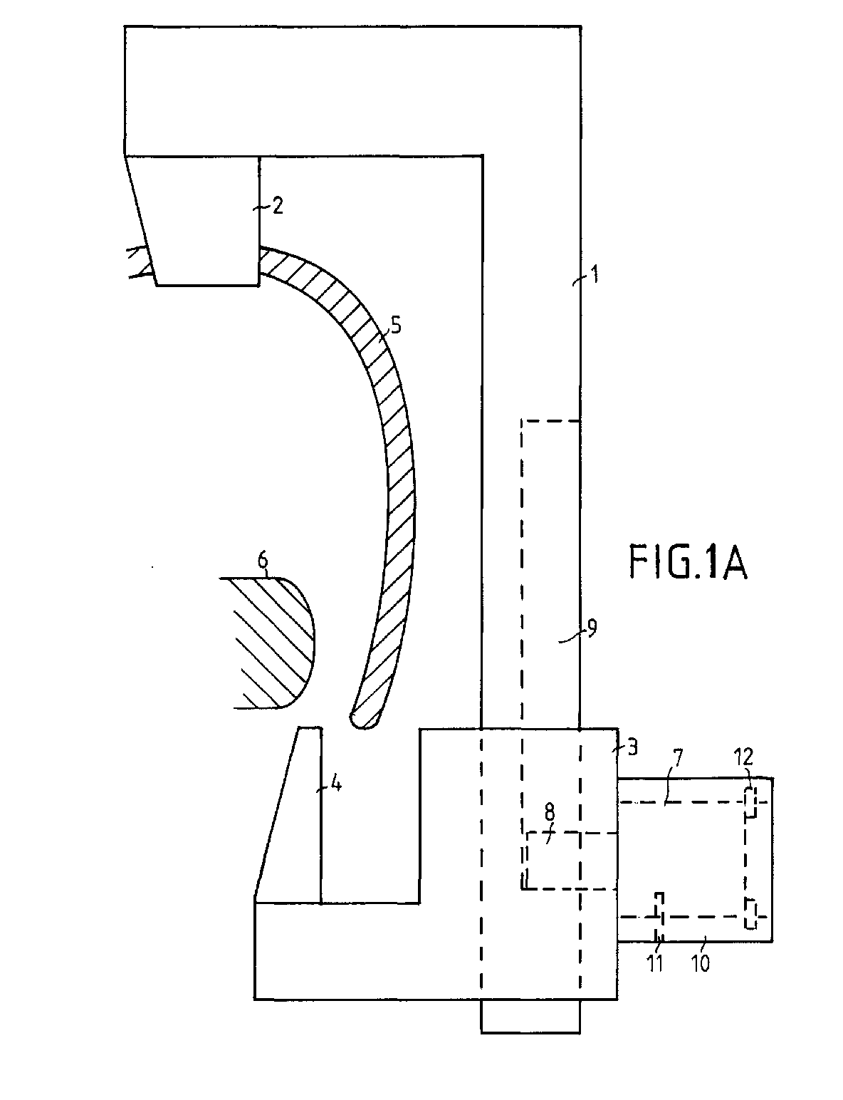
- Fig. 1A represents a first possible embodiment of an apparatus according to the invention, consisting of an L-shaped part 1, provided with a first pointed tip 2.
- L-shaped part 1 is rectangular in cross section and can slide in an opening with a corresponding rectangular cross section in a second part 3, provided with a second pointed tip 4.
- the apparatus is placed round a coupling means 5 in a vertical position as shown, which coupling means enclose a towing hook, not shown here.
- a tongue-shaped element 6 which forms part of a cup-shaped element which encloses the spherically shaped end of the towing hook, can move freely.
- pointed tip 2 By placing pointed tip 2 in an opening on the top side of coupling means 5, for example next to a grip with which tongue-shaped element 6 can be operated, and by pressing pointed tip 4 between coupling means 5 and tongue-shaped element 6, it is possible to block the coupling.
- pointed tip 2 and pointed tip 4 are moved at one another, by sliding second part 3 upward over L-shaped part 1.
- a cylinder lock 7 is provided, having a projection 8 which may slide freely inside a slot 9 in the long leg L-shaped part 1 when lock 7 is in a first position and which blocks when lock 7 is in a second position.
- Lock 7 is mounted in a sleeve 10, which forms an integral part of second part 3.
- a clamping bush 11 is used to fix lock 7 in sleeve 10, as usual in the art.
- a lock washer 12 can be placed in an internal groove in sleeve 10, which lock washer 12 is shaped such that it is almost impossible to remove it.
- Fig. 1B represents a possible embodiment of such a non-removable lock washer 12. With the aid of an auxiliary tool the lock washer can be compressed and placed inside the groove, after which it is practically impossible to remove it.
- the apparatus is made of steel, as usual in the art and has undergone a skin hardening process.
- Fig. 2A represents a slot 9 in the long leg of L-shaped part 1, through which a projection of the lock may slide.
- slot 9 consists of a series of joint holes.
- Fig. 2B represents lock 7 with projection 8 in a closed position, in which it is impossible to slide projection 8 through slot 9, as a result of which L-shaped part 1 cannot be slid through second part 3.
- Fig. 2C represents the lock with the projection in an open position, in which position it is possible to slide projection 8 through slot 9, such that also L-shaped part 1 can be slid through second part 3.
- the apparatus can be locked, it can be useful to provide the long leg of L-shaped part 1 with a number of lines 13a, 13b, 13c, .., next to one of which the edge of second part 3 can be placed before lock 7 is locked. If the apparatus has only two discrete positions, then it is sufficient to make a slot 9 by drilling only two holes and by connecting these holes with a relatively small slot.
- Fig. 3 represents a second possible embodiment of the apparatus according to the invention, consisting of a first part 14, provided with a first pointed tip 15.
- First part 14 is rectangular in cross section and can slide in an opening with a corresponding rectangular cross section in a second part 16, provided with a second pointed tip 17.
- the apparatus is shown in a horizontal position, placed round a coupling means 5, which coupling means enclose a towing hook, not shown here.
- a tongue-shaped element 6 which forms part of a cup-shaped element that encloses the spherically shaped end of the towing hook, can move freely.
- tongue-shaped element 6 is connected to two shafts 18a,18b, which may slide in two slots in coupling means 5.
- pointed tip 15 and pointed tip 17 By placing pointed tip 15 and pointed tip 17 in both oppositely placed slots and by mutually locking them, it is possible to block tongue-shaped element 6 and consequently the coupling as well.
- pointed tip 15 and pointed tip 17 are moved at one another, by sliding second part 16 over first part 14.
- a cylinder lock 7 is provided, having a projection 8 which may slide freely inside a slot 19 in the long leg of first part 14 if lock 7 is in a first position and which blocks when lock 7 is in a second position.
- Lock 7 is mounted in a sleeve 20, which forms an integral part of second part 16.
- both pointed tips are different, because they have to fit into different types of holes.
- both pointed tips are equal. It is to be expected that at least 90% of the existing couplings can be protected by one of the two embodiments shown here. More in particular it may be said that for a particular type of coupling, an apparatus according to the invention can be produced which locks that type of coupling, without the need of making additional holes in the coupling.
Landscapes
- Engineering & Computer Science (AREA)
- Transportation (AREA)
- Mechanical Engineering (AREA)
- Burglar Alarm Systems (AREA)
- Clamps And Clips (AREA)
- Hooks, Suction Cups, And Attachment By Adhesive Means (AREA)
- Snaps, Bayonet Connections, Set Pins, And Snap Rings (AREA)
- Lock And Its Accessories (AREA)
Abstract
Description
- The invention relates to an apparatus for securing a coupling between a towing hook and coupling means mounted to a shaft, arranged for co-operating with the towing hook, which coupling means comprise a cup-shaped element which operationally encloses a substantially spherically shaped end of the towing hook and which is provided with a tongue-shaped element that forms part of the cup-shaped element, at least when coupled to the towing hook, which tongue-shaped element is coupled to decoupling means.
- An apparatus of this kind is known from for
example EP 0 446 498. The known apparatus covers substantially the entire coupling means, such that it becomes inaccessible. Moreover it prevents the decoupling means, implemented as a grip, from being operated. The disadvantage of the known apparatus is that many different types are needed for the different types of coupling means, which increases production costs and logistics costs. The protection according to the invention substantially obviates these drawbacks and is characterized in that the apparatus comprises a clamp, provided with two pointed tips, which pointed tips operationally enter the coupling means via two holes, thereby blocking the tongue-shaped element in such a position that the spherical end of the towing hook cannot leave the cup-shaped element. It is then also impossible to introduce a spherically shaped end of a towing hook into the cup-shaped element, which seriously complicates the stealing of a disconnected trailer. It is expected that at least 90% of the existing coupling means can be protected with two or three different clamps according to the invention. - A very favourable embodiment of the invention, for which it is not necessary to adapt the coupling means, is characterized in that the pointed tips are shaped such as to fit in already available holes.
- A very light and yet robust embodiment is characterized in that the clamp comprises a first, L-shaped part and a second part which can slide across a longest leg of the first part, that the first part and the second part both are provided with a pointed tip, that the longest leg is provided with at least one cavity and that the second part is provided with a lock which may co-operate with the at least one cavity.
- Another favourable embodiment, which makes it possible to use the inventive apparatus in combination with a large number of different coupling means, is characterized in that the cavity comprises a lengthwise positioned slot provided with broadened sections. The second part is then preferably provided with a lock, of which a projection operationally can slide through the slot and/or can be fixed in a broadened section.
- Another favourable embodiment that makes it very difficult to prize open the apparatus is characterized in that the lock is accommodated in a sleeve, which forms an integral part of the second part.
- Another favourable embodiment of the inventive apparatus is characterized in that one pointed tip is arranged for penetrating a cavity adjacent to the decoupling means and the other pointed tip is arranged for penetrating like a wedge a space between the coupling means and the tongue-shaped element. In this embodiment, the long leg of the first, L-shaped part is operationally in a vertical position alongside the shaft.
- A favourable alternative embodiment of the inventive apparatus is characterized in that both pointed tips are arranged for penetrating the coupling means from opposite sides via openings along which the tongue-shaped element is guided in a longitudinal direction. In this embodiment, the long leg of the first, L-shaped part is operationally in a horizontal position above or beneath the shaft.
- The invention will now be further explained with a reference to the following figures, in which:
- Fig. 1A represents a first possible embodiment of an apparatus according to the invention;
- Fig. 1B represents a non-removable lock washer;
- Fig. 2A represents a slot, through which a projection of the lock may slide;
- Fig. 2B represents the lock with the projection in a closed position;
- Fig. 2C represents the lock with the projection in an open position;
- Fig. 3 represents a second possible embodiment of the apparatus according to the invention.
-
- Fig. 1A represents a first possible embodiment of an apparatus according to the invention, consisting of an L-
shaped part 1, provided with a firstpointed tip 2. L-shaped part 1 is rectangular in cross section and can slide in an opening with a corresponding rectangular cross section in asecond part 3, provided with a second pointed tip 4. The apparatus is placed round a coupling means 5 in a vertical position as shown, which coupling means enclose a towing hook, not shown here. For removing it from the towing hook it is essential that a tongue-shaped element 6 which forms part of a cup-shaped element which encloses the spherically shaped end of the towing hook, can move freely. By placingpointed tip 2 in an opening on the top side of coupling means 5, for example next to a grip with which tongue-shaped element 6 can be operated, and by pressing pointed tip 4 between coupling means 5 and tongue-shaped element 6, it is possible to block the coupling. For that purpose,pointed tip 2 and pointed tip 4 are moved at one another, by slidingsecond part 3 upward over L-shaped part 1. In order to lock the apparatus, acylinder lock 7 is provided, having a projection 8 which may slide freely inside a slot 9 in the long leg L-shapedpart 1 whenlock 7 is in a first position and which blocks whenlock 7 is in a second position.Lock 7 is mounted in a sleeve 10, which forms an integral part ofsecond part 3. In order to preventlock 7 from being removed from sleeve 10, aclamping bush 11 is used to fix lock 7 in sleeve 10, as usual in the art. As an additional precautionary measure, alock washer 12 can be placed in an internal groove in sleeve 10, whichlock washer 12 is shaped such that it is almost impossible to remove it. Fig. 1B represents a possible embodiment of such a non-removablelock washer 12. With the aid of an auxiliary tool the lock washer can be compressed and placed inside the groove, after which it is practically impossible to remove it. Moreover, the apparatus is made of steel, as usual in the art and has undergone a skin hardening process. - Fig. 2A represents a slot 9 in the long leg of L-
shaped part 1, through which a projection of the lock may slide. In this embodiment, slot 9 consists of a series of joint holes. Fig. 2B representslock 7 with projection 8 in a closed position, in which it is impossible to slide projection 8 through slot 9, as a result of which L-shaped part 1 cannot be slid throughsecond part 3. Fig. 2C represents the lock with the projection in an open position, in which position it is possible to slide projection 8 through slot 9, such that also L-shaped part 1 can be slid throughsecond part 3. - In order to indicate in which positions the apparatus can be locked, it can be useful to provide the long leg of L-
shaped part 1 with a number oflines second part 3 can be placed beforelock 7 is locked. If the apparatus has only two discrete positions, then it is sufficient to make a slot 9 by drilling only two holes and by connecting these holes with a relatively small slot. - Fig. 3 represents a second possible embodiment of the apparatus according to the invention, consisting of a
first part 14, provided with a firstpointed tip 15.
First part 14 is rectangular in cross section and can slide in an opening with a corresponding rectangular cross section in asecond part 16, provided with a secondpointed tip 17. The apparatus is shown in a horizontal position, placed round a coupling means 5, which coupling means enclose a towing hook, not shown here. For removing it from the towing hook, it is essential that a tongue-shaped element 6, which forms part of a cup-shaped element that encloses the spherically shaped end of the towing hook, can move freely. In this embodiment, tongue-shaped element 6 is connected to twoshafts pointed tip 15 andpointed tip 17 in both oppositely placed slots and by mutually locking them, it is possible to block tongue-shaped element 6 and consequently the coupling as well. In the process of locking,pointed tip 15 andpointed tip 17 are moved at one another, by slidingsecond part 16 overfirst part 14. In order to lock the apparatus, acylinder lock 7 is provided, having a projection 8 which may slide freely inside aslot 19 in the long leg offirst part 14 iflock 7 is in a first position and which blocks whenlock 7 is in a second position.Lock 7 is mounted in asleeve 20, which forms an integral part ofsecond part 16. - In the first embodiment of the apparatus, as shown in Fig. 1A, both pointed tips are different, because they have to fit into different types of holes. In the second embodiment, as shown in Fig. 3, both pointed tips are equal. It is to be expected that at least 90% of the existing couplings can be protected by one of the two embodiments shown here. More in particular it may be said that for a particular type of coupling, an apparatus according to the invention can be produced which locks that type of coupling, without the need of making additional holes in the coupling.
Claims (8)
- Apparatus for securing a coupling between a towing hook and coupling means mounted to a shaft, arranged for co-operating with the towing hook, which coupling means comprise a cup-shaped element which operationally encloses a substantially spherically shaped end of the towing hook and which is provided with a tongue-shaped element that forms part of the cup-shaped element, at least when coupled to the towing hook, which tongue-shaped element is coupled to decoupling means, characterized in that the apparatus comprises a clamp, provided with two pointed tips, which pointed tips operationally enter the coupling means via two holes, thereby blocking the tongue-shaped element.
- Apparatus according to claim 1, characterized in that the pointed tips are shaped such as to fit in already available holes.
- Apparatus according to claim 1 or 2, characterized in that the clamp comprises a first, L-shaped part and a second part which can slide across a longest leg of the first part, that the first part and the second part both are provided with a pointed tip, that the longest leg is provided with at least one cavity and that the second part is provided with a lock which may co-operate with the at least one cavity.
- Apparatus according to claim 3, characterized in that the cavity comprises a lengthwise positioned slot, provided with broadened sections.
- Apparatus according to claim 4, characterized in that the second part is provided with a lock, of which a projection operationally can slide through the slot and/or can be fixed in a broadened section.
- Apparatus according to claim 5, characterized in that the lock is accommodated in a sleeve which forms an integral part of the second part.
- Apparatus according to claim 3, characterized in that one pointed tip is arranged for penetrating a cavity adjacent to the decoupling means and the other pointed tip is arranged for penetrating like a wedge a space between the coupling means and the tongue-shaped element.
- Apparatus according to claim 3, characterized in that both pointed tips are arranged for penetrating the coupling means from opposite sides via openings along which the tongue-shaped element is guided in a longitudinal direction.
Priority Applications (1)
| Application Number | Priority Date | Filing Date | Title |
|---|---|---|---|
| DE20122057U DE20122057U1 (en) | 2000-11-29 | 2001-11-24 | Theft prevention device for prevention of uncoupling or coupling of trailer towing hook and coupling unit which co-operate with the towing hook and which are mounted to shaft |
Applications Claiming Priority (2)
| Application Number | Priority Date | Filing Date | Title |
|---|---|---|---|
| NL1016742A NL1016742C1 (en) | 2000-11-29 | 2000-11-29 | Protection for a towbar and an associated coupling device. |
| NL1016742 | 2000-11-29 |
Publications (3)
| Publication Number | Publication Date |
|---|---|
| EP1211105A2 true EP1211105A2 (en) | 2002-06-05 |
| EP1211105A3 EP1211105A3 (en) | 2002-11-27 |
| EP1211105B1 EP1211105B1 (en) | 2006-10-04 |
Family
ID=19772491
Family Applications (1)
| Application Number | Title | Priority Date | Filing Date |
|---|---|---|---|
| EP01204551A Expired - Lifetime EP1211105B1 (en) | 2000-11-29 | 2001-11-24 | Theft protection means for trailer coupling |
Country Status (4)
| Country | Link |
|---|---|
| EP (1) | EP1211105B1 (en) |
| AT (1) | ATE341456T1 (en) |
| DE (1) | DE60123554T2 (en) |
| NL (1) | NL1016742C1 (en) |
Citations (1)
| Publication number | Priority date | Publication date | Assignee | Title |
|---|---|---|---|---|
| EP0446498A2 (en) | 1990-02-06 | 1991-09-18 | Mewaho Beheer B.V. | Protection of the coupling between a motor vehicle and a trailer |
Family Cites Families (3)
| Publication number | Priority date | Publication date | Assignee | Title |
|---|---|---|---|---|
| US4836570A (en) * | 1988-04-07 | 1989-06-06 | Lopez Alfred G | Trailer hitch |
| WO1996005989A1 (en) * | 1993-08-02 | 1996-02-29 | Richard Smith | Trailer vehicle security device |
| AU690600B2 (en) * | 1994-01-17 | 1998-04-30 | Benedict James Hogan | A mobile trailer portable security lock |
-
2000
- 2000-11-29 NL NL1016742A patent/NL1016742C1/en not_active IP Right Cessation
-
2001
- 2001-11-24 AT AT01204551T patent/ATE341456T1/en not_active IP Right Cessation
- 2001-11-24 EP EP01204551A patent/EP1211105B1/en not_active Expired - Lifetime
- 2001-11-24 DE DE60123554T patent/DE60123554T2/en not_active Expired - Lifetime
Patent Citations (1)
| Publication number | Priority date | Publication date | Assignee | Title |
|---|---|---|---|---|
| EP0446498A2 (en) | 1990-02-06 | 1991-09-18 | Mewaho Beheer B.V. | Protection of the coupling between a motor vehicle and a trailer |
Also Published As
| Publication number | Publication date |
|---|---|
| ATE341456T1 (en) | 2006-10-15 |
| DE60123554D1 (en) | 2006-11-16 |
| NL1016742C1 (en) | 2002-05-31 |
| DE60123554T2 (en) | 2007-08-16 |
| EP1211105B1 (en) | 2006-10-04 |
| EP1211105A3 (en) | 2002-11-27 |
Similar Documents
| Publication | Publication Date | Title |
|---|---|---|
| US7210201B2 (en) | Clamp coupling for pipes | |
| EP0831199A3 (en) | Multi-purpose lockout | |
| EP1260430A3 (en) | Clamp for a cross bar | |
| WO2003078183A3 (en) | Locking device for trailer hitches and method therefor | |
| WO2002094086A3 (en) | Retractor clamp assembly | |
| JP3331464B2 (en) | Detachment device for connecting pin in synthetic resin conveyor chain | |
| ATE281568T1 (en) | UNIVERSAL COUPLING DEVICE FOR EXCAVATOR BUCKETS | |
| US4693096A (en) | Brake line coupler lock | |
| GB0015328D0 (en) | Locking system | |
| EP1039586A1 (en) | Connector assembly | |
| US5586903A (en) | Plug connector in which the cables are led out at an angle and with a releasable secondary lock | |
| CA3087759A1 (en) | Torque wrench and reaction arm assembly | |
| EP1211105A2 (en) | Theft protection means for trailer coupling | |
| GB2139278A (en) | Connector device | |
| EP0943494A3 (en) | Article carrier having single sided releasable and removable cross bar | |
| US20040175981A1 (en) | Plate locking system for mated electrical connectors and methods thereof | |
| US3825284A (en) | Safety hitch pin | |
| EP1124029A1 (en) | Lock | |
| DE69712468D1 (en) | LOCK FOR FIREARMS | |
| ATE151136T1 (en) | QUICK COUPLING SYSTEM FOR EXCAVATOR BUCKET | |
| US20020136600A1 (en) | Coupling device incorporating a security feature | |
| RU152996U1 (en) | DIAGNOSTIC CLUTCH FOR VEHICLE VEHICLES | |
| EP1256678A3 (en) | Locking means | |
| GB2275663A (en) | Anti-theft track clamp for track-laying vehicles. | |
| US20060099844A1 (en) | Plate locking systems for mated electrical connectors and methods thereof |
Legal Events
| Date | Code | Title | Description |
|---|---|---|---|
| PUAI | Public reference made under article 153(3) epc to a published international application that has entered the european phase |
Free format text: ORIGINAL CODE: 0009012 |
|
| AK | Designated contracting states |
Kind code of ref document: A2 Designated state(s): AT BE CH CY DE DK ES FI FR GB GR IE IT LI LU MC NL PT SE TR |
|
| AX | Request for extension of the european patent |
Free format text: AL;LT;LV;MK;RO;SI |
|
| PUAL | Search report despatched |
Free format text: ORIGINAL CODE: 0009013 |
|
| AK | Designated contracting states |
Kind code of ref document: A3 Designated state(s): AT BE CH CY DE DK ES FI FR GB GR IE IT LI LU MC NL PT SE TR |
|
| AX | Request for extension of the european patent |
Free format text: AL;LT;LV;MK;RO;SI |
|
| 17P | Request for examination filed |
Effective date: 20030507 |
|
| AKX | Designation fees paid |
Designated state(s): AT BE CH CY DE DK ES FI FR GB GR IE IT LI LU MC NL PT SE TR |
|
| 17Q | First examination report despatched |
Effective date: 20041208 |
|
| GRAP | Despatch of communication of intention to grant a patent |
Free format text: ORIGINAL CODE: EPIDOSNIGR1 |
|
| GRAS | Grant fee paid |
Free format text: ORIGINAL CODE: EPIDOSNIGR3 |
|
| GRAA | (expected) grant |
Free format text: ORIGINAL CODE: 0009210 |
|
| AK | Designated contracting states |
Kind code of ref document: B1 Designated state(s): AT BE CH CY DE DK ES FI FR GB GR IE IT LI LU MC NL PT SE TR |
|
| PG25 | Lapsed in a contracting state [announced via postgrant information from national office to epo] |
Ref country code: AT Free format text: LAPSE BECAUSE OF FAILURE TO SUBMIT A TRANSLATION OF THE DESCRIPTION OR TO PAY THE FEE WITHIN THE PRESCRIBED TIME-LIMIT Effective date: 20061004 Ref country code: LI Free format text: LAPSE BECAUSE OF FAILURE TO SUBMIT A TRANSLATION OF THE DESCRIPTION OR TO PAY THE FEE WITHIN THE PRESCRIBED TIME-LIMIT Effective date: 20061004 Ref country code: CH Free format text: LAPSE BECAUSE OF FAILURE TO SUBMIT A TRANSLATION OF THE DESCRIPTION OR TO PAY THE FEE WITHIN THE PRESCRIBED TIME-LIMIT Effective date: 20061004 Ref country code: BE Free format text: LAPSE BECAUSE OF FAILURE TO SUBMIT A TRANSLATION OF THE DESCRIPTION OR TO PAY THE FEE WITHIN THE PRESCRIBED TIME-LIMIT Effective date: 20061004 Ref country code: IT Free format text: LAPSE BECAUSE OF FAILURE TO SUBMIT A TRANSLATION OF THE DESCRIPTION OR TO PAY THE FEE WITHIN THE PRESCRIBED TIME-LIMIT;WARNING: LAPSES OF ITALIAN PATENTS WITH EFFECTIVE DATE BEFORE 2007 MAY HAVE OCCURRED AT ANY TIME BEFORE 2007. THE CORRECT EFFECTIVE DATE MAY BE DIFFERENT FROM THE ONE RECORDED. Effective date: 20061004 Ref country code: FI Free format text: LAPSE BECAUSE OF FAILURE TO SUBMIT A TRANSLATION OF THE DESCRIPTION OR TO PAY THE FEE WITHIN THE PRESCRIBED TIME-LIMIT Effective date: 20061004 |
|
| REG | Reference to a national code |
Ref country code: GB Ref legal event code: FG4D |
|
| REG | Reference to a national code |
Ref country code: CH Ref legal event code: EP |
|
| REG | Reference to a national code |
Ref country code: IE Ref legal event code: FG4D |
|
| REF | Corresponds to: |
Ref document number: 60123554 Country of ref document: DE Date of ref document: 20061116 Kind code of ref document: P |
|
| PG25 | Lapsed in a contracting state [announced via postgrant information from national office to epo] |
Ref country code: IE Free format text: LAPSE BECAUSE OF NON-PAYMENT OF DUE FEES Effective date: 20061124 |
|
| PG25 | Lapsed in a contracting state [announced via postgrant information from national office to epo] |
Ref country code: MC Free format text: LAPSE BECAUSE OF NON-PAYMENT OF DUE FEES Effective date: 20061130 |
|
| PG25 | Lapsed in a contracting state [announced via postgrant information from national office to epo] |
Ref country code: SE Free format text: LAPSE BECAUSE OF FAILURE TO SUBMIT A TRANSLATION OF THE DESCRIPTION OR TO PAY THE FEE WITHIN THE PRESCRIBED TIME-LIMIT Effective date: 20070104 Ref country code: DK Free format text: LAPSE BECAUSE OF FAILURE TO SUBMIT A TRANSLATION OF THE DESCRIPTION OR TO PAY THE FEE WITHIN THE PRESCRIBED TIME-LIMIT Effective date: 20070104 |
|
| PG25 | Lapsed in a contracting state [announced via postgrant information from national office to epo] |
Ref country code: ES Free format text: LAPSE BECAUSE OF FAILURE TO SUBMIT A TRANSLATION OF THE DESCRIPTION OR TO PAY THE FEE WITHIN THE PRESCRIBED TIME-LIMIT Effective date: 20070115 |
|
| PG25 | Lapsed in a contracting state [announced via postgrant information from national office to epo] |
Ref country code: PT Free format text: LAPSE BECAUSE OF FAILURE TO SUBMIT A TRANSLATION OF THE DESCRIPTION OR TO PAY THE FEE WITHIN THE PRESCRIBED TIME-LIMIT Effective date: 20070316 |
|
| ET | Fr: translation filed | ||
| REG | Reference to a national code |
Ref country code: CH Ref legal event code: PL |
|
| PLBE | No opposition filed within time limit |
Free format text: ORIGINAL CODE: 0009261 |
|
| STAA | Information on the status of an ep patent application or granted ep patent |
Free format text: STATUS: NO OPPOSITION FILED WITHIN TIME LIMIT |
|
| 26N | No opposition filed |
Effective date: 20070705 |
|
| PG25 | Lapsed in a contracting state [announced via postgrant information from national office to epo] |
Ref country code: GR Free format text: LAPSE BECAUSE OF FAILURE TO SUBMIT A TRANSLATION OF THE DESCRIPTION OR TO PAY THE FEE WITHIN THE PRESCRIBED TIME-LIMIT Effective date: 20070105 |
|
| PG25 | Lapsed in a contracting state [announced via postgrant information from national office to epo] |
Ref country code: TR Free format text: LAPSE BECAUSE OF FAILURE TO SUBMIT A TRANSLATION OF THE DESCRIPTION OR TO PAY THE FEE WITHIN THE PRESCRIBED TIME-LIMIT Effective date: 20061004 Ref country code: LU Free format text: LAPSE BECAUSE OF NON-PAYMENT OF DUE FEES Effective date: 20061124 |
|
| PG25 | Lapsed in a contracting state [announced via postgrant information from national office to epo] |
Ref country code: CY Free format text: LAPSE BECAUSE OF FAILURE TO SUBMIT A TRANSLATION OF THE DESCRIPTION OR TO PAY THE FEE WITHIN THE PRESCRIBED TIME-LIMIT Effective date: 20061004 |
|
| PGFP | Annual fee paid to national office [announced via postgrant information from national office to epo] |
Ref country code: FR Payment date: 20081113 Year of fee payment: 8 |
|
| REG | Reference to a national code |
Ref country code: FR Ref legal event code: ST Effective date: 20100730 |
|
| PG25 | Lapsed in a contracting state [announced via postgrant information from national office to epo] |
Ref country code: FR Free format text: LAPSE BECAUSE OF NON-PAYMENT OF DUE FEES Effective date: 20091130 |
|
| PGFP | Annual fee paid to national office [announced via postgrant information from national office to epo] |
Ref country code: DE Payment date: 20121121 Year of fee payment: 12 |
|
| PGFP | Annual fee paid to national office [announced via postgrant information from national office to epo] |
Ref country code: GB Payment date: 20121120 Year of fee payment: 12 |
|
| GBPC | Gb: european patent ceased through non-payment of renewal fee |
Effective date: 20131124 |
|
| PG25 | Lapsed in a contracting state [announced via postgrant information from national office to epo] |
Ref country code: DE Free format text: LAPSE BECAUSE OF NON-PAYMENT OF DUE FEES Effective date: 20140603 |
|
| REG | Reference to a national code |
Ref country code: DE Ref legal event code: R119 Ref document number: 60123554 Country of ref document: DE Effective date: 20140603 |
|
| PG25 | Lapsed in a contracting state [announced via postgrant information from national office to epo] |
Ref country code: GB Free format text: LAPSE BECAUSE OF NON-PAYMENT OF DUE FEES Effective date: 20131124 |
|
| PGFP | Annual fee paid to national office [announced via postgrant information from national office to epo] |
Ref country code: NL Payment date: 20141222 Year of fee payment: 14 |
|
| REG | Reference to a national code |
Ref country code: NL Ref legal event code: MM Effective date: 20151201 |
|
| PG25 | Lapsed in a contracting state [announced via postgrant information from national office to epo] |
Ref country code: NL Free format text: LAPSE BECAUSE OF NON-PAYMENT OF DUE FEES Effective date: 20151201 |