EP1211095B1 - Three-dimensional printing method - Google Patents
Three-dimensional printing method Download PDFInfo
- Publication number
- EP1211095B1 EP1211095B1 EP01309776A EP01309776A EP1211095B1 EP 1211095 B1 EP1211095 B1 EP 1211095B1 EP 01309776 A EP01309776 A EP 01309776A EP 01309776 A EP01309776 A EP 01309776A EP 1211095 B1 EP1211095 B1 EP 1211095B1
- Authority
- EP
- European Patent Office
- Prior art keywords
- ink
- coating
- printing process
- substrate
- printed
- Prior art date
- Legal status (The legal status is an assumption and is not a legal conclusion. Google has not performed a legal analysis and makes no representation as to the accuracy of the status listed.)
- Expired - Lifetime
Links
- 238000000034 method Methods 0.000 title claims description 31
- 238000010146 3D printing Methods 0.000 title 1
- 239000000976 ink Substances 0.000 claims description 54
- 238000007639 printing Methods 0.000 claims description 29
- 239000011347 resin Substances 0.000 claims description 27
- 229920005989 resin Polymers 0.000 claims description 27
- 239000000758 substrate Substances 0.000 claims description 24
- 238000000576 coating method Methods 0.000 claims description 18
- 239000010408 film Substances 0.000 claims description 18
- 239000011248 coating agent Substances 0.000 claims description 17
- 239000000654 additive Substances 0.000 claims description 9
- 230000000996 additive effect Effects 0.000 claims description 9
- 239000002966 varnish Substances 0.000 claims description 3
- 239000004721 Polyphenylene oxide Substances 0.000 claims description 2
- BLRPTPMANUNPDV-UHFFFAOYSA-N Silane Chemical compound [SiH4] BLRPTPMANUNPDV-UHFFFAOYSA-N 0.000 claims description 2
- 239000011888 foil Substances 0.000 claims description 2
- 239000011104 metalized film Substances 0.000 claims description 2
- 229920000570 polyether Polymers 0.000 claims description 2
- 229910000077 silane Inorganic materials 0.000 claims description 2
- 238000001035 drying Methods 0.000 claims 2
- 229920000134 Metallised film Polymers 0.000 claims 1
- 239000007788 liquid Substances 0.000 description 7
- 238000004049 embossing Methods 0.000 description 5
- 239000000203 mixture Substances 0.000 description 5
- 230000000007 visual effect Effects 0.000 description 4
- 238000007641 inkjet printing Methods 0.000 description 3
- 238000004519 manufacturing process Methods 0.000 description 3
- 238000004806 packaging method and process Methods 0.000 description 2
- 239000002245 particle Substances 0.000 description 2
- 229920000915 polyvinyl chloride Polymers 0.000 description 2
- 239000004800 polyvinyl chloride Substances 0.000 description 2
- XNCOSPRUTUOJCJ-UHFFFAOYSA-N Biguanide Chemical compound NC(N)=NC(N)=N XNCOSPRUTUOJCJ-UHFFFAOYSA-N 0.000 description 1
- 229940123208 Biguanide Drugs 0.000 description 1
- 239000011230 binding agent Substances 0.000 description 1
- 239000008199 coating composition Substances 0.000 description 1
- 229910003460 diamond Inorganic materials 0.000 description 1
- 239000010432 diamond Substances 0.000 description 1
- 238000003618 dip coating Methods 0.000 description 1
- 238000005516 engineering process Methods 0.000 description 1
- 230000002209 hydrophobic effect Effects 0.000 description 1
- 230000002045 lasting effect Effects 0.000 description 1
- 230000005923 long-lasting effect Effects 0.000 description 1
- 239000005022 packaging material Substances 0.000 description 1
- 239000011253 protective coating Substances 0.000 description 1
- 230000001681 protective effect Effects 0.000 description 1
- 239000000376 reactant Substances 0.000 description 1
- 238000007761 roller coating Methods 0.000 description 1
- 229910052710 silicon Inorganic materials 0.000 description 1
- 239000010703 silicon Substances 0.000 description 1
- 229920002545 silicone oil Polymers 0.000 description 1
- 238000005507 spraying Methods 0.000 description 1
- 239000004094 surface-active agent Substances 0.000 description 1
- 239000012970 tertiary amine catalyst Substances 0.000 description 1
Images

Classifications
-
- C—CHEMISTRY; METALLURGY
- C09—DYES; PAINTS; POLISHES; NATURAL RESINS; ADHESIVES; COMPOSITIONS NOT OTHERWISE PROVIDED FOR; APPLICATIONS OF MATERIALS NOT OTHERWISE PROVIDED FOR
- C09D—COATING COMPOSITIONS, e.g. PAINTS, VARNISHES OR LACQUERS; FILLING PASTES; CHEMICAL PAINT OR INK REMOVERS; INKS; CORRECTING FLUIDS; WOODSTAINS; PASTES OR SOLIDS FOR COLOURING OR PRINTING; USE OF MATERIALS THEREFOR
- C09D11/00—Inks
- C09D11/02—Printing inks
- C09D11/03—Printing inks characterised by features other than the chemical nature of the binder
-
- B—PERFORMING OPERATIONS; TRANSPORTING
- B41—PRINTING; LINING MACHINES; TYPEWRITERS; STAMPS
- B41M—PRINTING, DUPLICATING, MARKING, OR COPYING PROCESSES; COLOUR PRINTING
- B41M3/00—Printing processes to produce particular kinds of printed work, e.g. patterns
- B41M3/008—Sequential or multiple printing, e.g. on previously printed background; Mirror printing; Recto-verso printing; using a combination of different printing techniques; Printing of patterns visible in reflection and by transparency; by superposing printed artifacts
-
- B—PERFORMING OPERATIONS; TRANSPORTING
- B41—PRINTING; LINING MACHINES; TYPEWRITERS; STAMPS
- B41M—PRINTING, DUPLICATING, MARKING, OR COPYING PROCESSES; COLOUR PRINTING
- B41M7/00—After-treatment of prints, e.g. heating, irradiating, setting of the ink, protection of the printed stock
- B41M7/02—Dusting, e.g. with an anti-offset powder for obtaining raised printing such as by thermogravure ; Varnishing
-
- Y—GENERAL TAGGING OF NEW TECHNOLOGICAL DEVELOPMENTS; GENERAL TAGGING OF CROSS-SECTIONAL TECHNOLOGIES SPANNING OVER SEVERAL SECTIONS OF THE IPC; TECHNICAL SUBJECTS COVERED BY FORMER USPC CROSS-REFERENCE ART COLLECTIONS [XRACs] AND DIGESTS
- Y10—TECHNICAL SUBJECTS COVERED BY FORMER USPC
- Y10T—TECHNICAL SUBJECTS COVERED BY FORMER US CLASSIFICATION
- Y10T428/00—Stock material or miscellaneous articles
- Y10T428/24—Structurally defined web or sheet [e.g., overall dimension, etc.]
- Y10T428/24802—Discontinuous or differential coating, impregnation or bond [e.g., artwork, printing, retouched photograph, etc.]
- Y10T428/24893—Discontinuous or differential coating, impregnation or bond [e.g., artwork, printing, retouched photograph, etc.] including particulate material
- Y10T428/24901—Discontinuous or differential coating, impregnation or bond [e.g., artwork, printing, retouched photograph, etc.] including particulate material including coloring matter
Definitions
- the present invention relates to a method of printing and printed products. More specifically, the present invention relates to a method of printing profile ridges by applying resin to a low surface tension ink.
- Holograms present a three dimensional image to the consumer.
- holograms are expensive to produce, requiring high precision embossing equipment and tools.
- the capital expense required to produce holograms is high enough that holograms are often used as a security device.
- Simpler embossing methods can be used at lower cost than holograms to produce a graphic with a textured or raised look and feel. Embossing can produce interesting visual effects when a clear profile is embossed over an image. The underlying image appears differently from various viewing angles due to refraction of light through the embossed profile. However, even simple embossing equipment requires a significant capital expenditure.
- the present invention provides such a printing method, eliminating the need for embossing rollers, while providing a profile pattern of raised ridges over printed matter.
- EP Patent Application No 0,974,626 describes a process of making a long-lasting image on a hydrophobic substrate. The process involves ink jet printing an ink having a silicon or fluorinated surfactant. An overcoat composition is applied to the substrate subsequent to printing.
- EP Patent Application No 0,569,640 describes chemically embossed polyvinyl chloride film.
- a pattern of ink containing silicone oil is printed on the PVC film.
- a top coat is applied and is repelled from the silconized ink.
- the top coat is then cured by exposure to a tertiary amine catalyst.
- US Patent No 4,759,982 describes a process for preparing a transfer graphic article with a protective clear coat in precise registration with the graphic.
- the graphic is first printed on a carrier. Thereafter, a coating composition having a surface tension sufficient to wet the graphic pattern, but not the carrier, is applied.
- the coating is formulated to dewet or retract from the carrier into precise registration with the graphic pattern.
- International Patent Application WO 00/37258 describes an ink jet printing process in which a composition is coated onto paper prior to printing an image.
- the composition which contains a binder and a polymeric biguanide, is applied to the paper so that ink can be deposited on top of the composition.
- the composition can be applied by any convenient method, such as dip coating, reverse roller coating, K-bar coating, spraying, or by means of an ink jet printer.
- EP Patent Application No 1,022,151 describes a method of ink jet printing wherein ink is printed along with a first liquid having polymeric particles and a second liquid containing a reactant.
- the first liquid is applied over the ink to provide a protective coating.
- the polymeric particles of the first liquid cover the ink and coalesce or fuse together to form a film.
- the ink is covered with the film to improve rubbing/scratch resistance, waterfastness, gloss and lightfastness of the printed media.
- the first liquid can also be deposited before the ink is printed.
- the second liquid is also deposited onto the ink. The second liquid contacts the ink and forms coagulate.
- the present invention provides a printing process and a printed product in which ink is combined with an additive that lowers the surface tension of the dried ink film.
- the enhanced ink is printed onto a substrate in a pattern of parallel lines and allowed to dry.
- a clear resin or varnish is applied over or under the dried ink, and because of the difference in surface tension between the ink film and the substrate, the resin flows away from the ink film.
- the resin cures in a series of raised ridges oriented along the printed profile lines.
- the additive is formulated into the clear resin or varnish.
- the clear resin pattern is printed on a clear web.
- the clear pattern is dried and the ink is printed on top of the dried clear resin. This ink flows away from the clear resin due to the difference in surface tension, forming patterns of raised ink.
- This reverse-printed film is then laminated to a second film to complete the overall structure.
- Figures 1-3 show a section of printed matter according to the present invention.
- the ink is combined with an additive which lowers the surface tension of the dried ink film.
- an additive which lowers the surface tension of the dried ink film.
- One such additive is a hydroxy-modified polyether silane manufactured and sold by BYK-Chemie.
- the additive enhanced ink 12 is printed over the substrate 10 in a pattern of parallel profile lines, leaving spaces between adjacent lines of ink so that the substrate remains exposed.
- the substrate is preferably a non-printed metallized film, foil, or other reflective surface.
- Figure 1 shows a section of substrate 10 which has been overprinted with ink 12 m a profile pattern.
- the particular printing method used to apply the ink to the substrate is not important, and those of ordinary skill in the art will recognize that a variety of printing methods are available.
- One example of a suitable printing method is the rotogravure process. Rotogravure is preferable because it produces highly accurate images, while allowing for high press and production speeds. Rotogravure cylinders engraved by a laser engraver will yield both the production volume and continuous channels necessary to produce the desired visual effect.
- the laser engraver is capable of engraving deep continuous channel for the ink. Mechanical engraving with a diamond stylus will only produce large cells with narrow channels of a much smaller volume.
- a resin 14 is applied over the printed ink pattern area 12.
- the resin is preferably clear when dried.
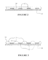
- Figure 2 shows a cross section of some printed matter immediately after the resin 14 has been applied.
- the resin 14 is in contact with both the printed dried ink film 12 and the substrate 10 between lines of ink 12. Because the surface tension of the dried ink film 12 is lower than the surface tension of the substrate 10, the resin 14 flows away from the dried ink film 12 and toward the areas of exposed substrate 10.
- Figure 3 shows a cross section of printed matter according to the invention after the resin 14 has completed its flow.
- the resin 14 has collected in the areas of exposed substrate 10 between the profile lines of ink 12.
- the resin 14 forms raised ridges 16 that are oriented along the patterned lines of ink 12.
- the resin is clear or translucent, refraction of light through the resin will cause the printed matter to change appearance when viewed from different angles.
- the resin 14 is allowed to set to form lasting raised profile ridges 16 oriented along the lines of the ink pattern 12.
- the resin would normally flow out to a continuous film and would not yield a refraction pattern as contemplated by the raised ridges in the present invention.
- Other visual effects can be created by the use of various colored or metallic inks that may be substituted for the clear profile resin.
- the clear resin is pattern applied with the additive first and then the ink is printed to form the patterns.
- Scuff resistance may also be achieved by reverse printing the ink and resin coating on a clear film and applying the film to a second substrate.
Landscapes
- Chemical & Material Sciences (AREA)
- Chemical Kinetics & Catalysis (AREA)
- General Chemical & Material Sciences (AREA)
- Life Sciences & Earth Sciences (AREA)
- Engineering & Computer Science (AREA)
- Materials Engineering (AREA)
- Wood Science & Technology (AREA)
- Organic Chemistry (AREA)
- Printing Methods (AREA)
- Laminated Bodies (AREA)
- Application Of Or Painting With Fluid Materials (AREA)
- Inks, Pencil-Leads, Or Crayons (AREA)
Description
- The present invention relates to a method of printing and printed products. More specifically, the present invention relates to a method of printing profile ridges by applying resin to a low surface tension ink.
- In today's marketplace, products are often distinguished as much by the packaging in which they are presented as the quality of the product itself. A package which catches the eye of the consumer is therefore very desirable. To that end, increasingly colorful and creative graphics have been applied to packaging in an attempt to distinguish one package, and hence one product, from another.
- One popular graphic with visual appeal for consumers is the hologram. Holograms present a three dimensional image to the consumer. Unfortunately, holograms are expensive to produce, requiring high precision embossing equipment and tools. The capital expense required to produce holograms is high enough that holograms are often used as a security device.
- Simpler embossing methods can be used at lower cost than holograms to produce a graphic with a textured or raised look and feel. Embossing can produce interesting visual effects when a clear profile is embossed over an image. The underlying image appears differently from various viewing angles due to refraction of light through the embossed profile. However, even simple embossing equipment requires a significant capital expenditure.
- Thus, there is a need for a simpler, less expensive technology for printing packaging material with a visually appealing, textured look and feel. The present invention provides such a printing method, eliminating the need for embossing rollers, while providing a profile pattern of raised ridges over printed matter.
- EP Patent Application No 0,974,626 describes a process of making a long-lasting image on a hydrophobic substrate. The process involves ink jet printing an ink having a silicon or fluorinated surfactant. An overcoat composition is applied to the substrate subsequent to printing.
- EP Patent Application No 0,569,640 describes chemically embossed polyvinyl chloride film. A pattern of ink containing silicone oil is printed on the PVC film. Thereafter, a top coat is applied and is repelled from the silconized ink. The top coat is then cured by exposure to a tertiary amine catalyst.
- US Patent No 4,759,982 describes a process for preparing a transfer graphic article with a protective clear coat in precise registration with the graphic. The graphic is first printed on a carrier. Thereafter, a coating composition having a surface tension sufficient to wet the graphic pattern, but not the carrier, is applied. The coating is formulated to dewet or retract from the carrier into precise registration with the graphic pattern.
- International Patent Application WO 00/37258 describes an ink jet printing process in which a composition is coated onto paper prior to printing an image. The composition, which contains a binder and a polymeric biguanide, is applied to the paper so that ink can be deposited on top of the composition. The composition can be applied by any convenient method, such as dip coating, reverse roller coating, K-bar coating, spraying, or by means of an ink jet printer.
- EP Patent Application No 1,022,151 describes a method of ink jet printing wherein ink is printed along with a first liquid having polymeric particles and a second liquid containing a reactant. The first liquid is applied over the ink to provide a protective coating. The polymeric particles of the first liquid cover the ink and coalesce or fuse together to form a film. The ink is covered with the film to improve rubbing/scratch resistance, waterfastness, gloss and lightfastness of the printed media. In order to further improve these qualities, the first liquid can also be deposited before the ink is printed. The second liquid is also deposited onto the ink. The second liquid contacts the ink and forms coagulate.
- The present invention provides a printing process and a printed product in which ink is combined with an additive that lowers the surface tension of the dried ink film. The enhanced ink is printed onto a substrate in a pattern of parallel lines and allowed to dry. A clear resin or varnish is applied over or under the dried ink, and because of the difference in surface tension between the ink film and the substrate, the resin flows away from the ink film. The resin cures in a series of raised ridges oriented along the printed profile lines.
- For reverse printed applications, the additive is formulated into the clear resin or varnish. The clear resin pattern is printed on a clear web. The clear pattern is dried and the ink is printed on top of the dried clear resin. This ink flows away from the clear resin due to the difference in surface tension, forming patterns of raised ink. This reverse-printed film is then laminated to a second film to complete the overall structure.
- For the purposes of illustrating the invention, there is shown in the drawings a form which is presently preferred; it being understood, however, that this invention is not limited to the precise arrangements and instrumentalities shown.
- Figure 1 is a top view of a portion of printed matter according to the present invention.
- Figure 2 is a cross section showing clear resin applied to a substrate and ink lines according to the present invention before any flow has occurred in the resin due to different surface tensions.
- Figure 3 is a cross section of printed matter according to the present invention.
-
- In order to more clearly illustrate the invention, Figures 1-3 show a section of printed matter according to the present invention. Before printing, the ink is combined with an additive which lowers the surface tension of the dried ink film. One such additive is a hydroxy-modified polyether silane manufactured and sold by BYK-Chemie. The additive enhanced
ink 12 is printed over thesubstrate 10 in a pattern of parallel profile lines, leaving spaces between adjacent lines of ink so that the substrate remains exposed. The substrate is preferably a non-printed metallized film, foil, or other reflective surface. - Figure 1 shows a section of
substrate 10 which has been overprinted withink 12 m a profile pattern. The particular printing method used to apply the ink to the substrate is not important, and those of ordinary skill in the art will recognize that a variety of printing methods are available. One example of a suitable printing method is the rotogravure process. Rotogravure is preferable because it produces highly accurate images, while allowing for high press and production speeds. Rotogravure cylinders engraved by a laser engraver will yield both the production volume and continuous channels necessary to produce the desired visual effect. - The laser engraver is capable of engraving deep continuous channel for the ink. Mechanical engraving with a diamond stylus will only produce large cells with narrow channels of a much smaller volume.
- A
resin 14 is applied over the printedink pattern area 12. The resin is preferably clear when dried. Figure 2 shows a cross section of some printed matter immediately after theresin 14 has been applied. Theresin 14 is in contact with both the printed driedink film 12 and thesubstrate 10 between lines ofink 12. Because the surface tension of the driedink film 12 is lower than the surface tension of thesubstrate 10, theresin 14 flows away from the driedink film 12 and toward the areas of exposedsubstrate 10. - Figure 3 shows a cross section of printed matter according to the invention after the
resin 14 has completed its flow. Theresin 14 has collected in the areas of exposedsubstrate 10 between the profile lines ofink 12. Thus, theresin 14 forms raisedridges 16 that are oriented along the patterned lines ofink 12. Because the resin is clear or translucent, refraction of light through the resin will cause the printed matter to change appearance when viewed from different angles. Theresin 14 is allowed to set to form lasting raisedprofile ridges 16 oriented along the lines of theink pattern 12. - Without the additive in the ink the resin would normally flow out to a continuous film and would not yield a refraction pattern as contemplated by the raised ridges in the present invention. Other visual effects can be created by the use of various colored or metallic inks that may be substituted for the clear profile resin. For reverse printed applications, the clear resin is pattern applied with the additive first and then the ink is printed to form the patterns.
- It should be understood that when producing the printed structure on press, independent registration control is possible for the individual profile stations, resulting in better overall registration. Further, by the use of a laser engraver, highly accurate patterns can be created. Also, more volume of the resin or coating can be deposited on the surface due to the large volume of cells produced on the laser engraver. This large volume is possible with the present invention substantially without the occurrence of "flow outs".
- It is contemplated that further variations of the present invention are possible by the use of four color printing techniques and by the addition of scuff resistant coatings or the like. Scuff resistance may also be achieved by reverse printing the ink and resin coating on a clear film and applying the film to a second substrate.
- The present invention may be embodied in still further specific forms without departing from the essential attributes thereof and, accordingly, reference should be made to the appended claims, rather than to the foregoing specification, as indicating the scope of the invention.
Claims (14)
- A printing process using a clear coating and a printing ink, including the steps of:(a) adding a surface tension lowering additive to the coating;(b) printing the coating onto a substrate in a pattern of parallel lines such that non-printed areas remain between the parallel lines of printed coating;(c) drying the coating;(d) applying the ink over the substrate and the coating;(e) allowing the ink to flow from the coating printed areas to the non-printed areas until the ink forms raised ridges oriented along the lines of the coating pattern; and(f) drying the ink.
- A printing process as claimed in claim 1 wherein the substrate is a metallised film.
- A printing process as claimed in claim 1, wherein the additive is hydroxy-modified polyether silane.
- A printing process as claimed in claim 1 wherein the coating and ink are reverse printed onto the substrate.
- A printing process as claimed in claim 1 wherein the coating is a resin.
- A printing process as claimed in claim 1 wherein the coating is a varnish.
- A printing process as claimed in claim 1 wherein the ink is a pattern of coloured inks.
- A printing process as claimed in claim 1 wherein the ink is a pattern of metallic ink.
- A printing process as claimed in claim 1 wherein the substrate is a reflective surface.
- A printing process as claimed in claim 9 wherein the reflective substrate is a foil.
- A printing process as claimed in claim 1 or 4 wherein the substrate is a clear film.
- A printing process as claimed in claim 11 wherein the process further comprises the step of securing the printed film to a second substrate, with the ink and coating positioned between the first and second substrates.
- A printing process as claimed in claim 1 wherein the coating is printed using laser engraved rotogravure.
- A printing process as claimed in claim 1 or claim 13 wherein the ink is applied using laser engraved rotogravure.
Applications Claiming Priority (2)
| Application Number | Priority Date | Filing Date | Title |
|---|---|---|---|
| US724992 | 2000-11-27 | ||
| US09/724,992 US6546872B1 (en) | 2000-11-27 | 2000-11-27 | Profile printing method with additive technology |
Publications (2)
| Publication Number | Publication Date |
|---|---|
| EP1211095A1 EP1211095A1 (en) | 2002-06-05 |
| EP1211095B1 true EP1211095B1 (en) | 2004-07-21 |
Family
ID=24912693
Family Applications (1)
| Application Number | Title | Priority Date | Filing Date |
|---|---|---|---|
| EP01309776A Expired - Lifetime EP1211095B1 (en) | 2000-11-27 | 2001-11-21 | Three-dimensional printing method |
Country Status (9)
| Country | Link |
|---|---|
| US (1) | US6546872B1 (en) |
| EP (1) | EP1211095B1 (en) |
| JP (1) | JP2002225413A (en) |
| AR (1) | AR031421A1 (en) |
| AU (1) | AU778688B2 (en) |
| BR (1) | BR0105731A (en) |
| CA (1) | CA2364119A1 (en) |
| DE (1) | DE60104386T2 (en) |
| MX (1) | MXPA01012272A (en) |
Families Citing this family (27)
| Publication number | Priority date | Publication date | Assignee | Title |
|---|---|---|---|---|
| DE10146912A1 (en) * | 2001-09-24 | 2003-04-10 | Giesecke & Devrient Gmbh | Procedure for individualizing security documents and corresponding security document |
| US7131380B2 (en) * | 2001-11-07 | 2006-11-07 | Sonoco Development, Inc. | EB pattern profile printing |
| US20030175067A1 (en) * | 2002-03-15 | 2003-09-18 | Pearce Jerry W. | Web process for making a binder case |
| JP2004095242A (en) * | 2002-08-30 | 2004-03-25 | Tsubame Musen Kk | Rotary encoder and manufacturing method for substrate of the same |
| US7403309B2 (en) * | 2004-04-05 | 2008-07-22 | Moncrieff Scott E | Method for producing printed image having 3-dimensional appearance |
| DE102006003311A1 (en) * | 2006-01-23 | 2007-07-26 | Man Roland Druckmaschinen Ag | Method for producing printed image effects with directional viewing by applying spatial pattern lacquer layer to form mini lens array |
| CN101616807B (en) * | 2006-11-14 | 2013-03-20 | 反相有限公司 | Improvements to printing superimposed layers |
| US7639426B2 (en) * | 2007-12-05 | 2009-12-29 | Eastman Kodak Company | Micro-lens enhanced element |
| FR2939717A1 (en) * | 2008-12-12 | 2010-06-18 | Franck Andre Marie Guigan | Printed optical element e.g. microlens, fabricating method for e.g. optical circuit, involves depositing liquid substance on substrate by opposition of fabrication techniques comprising deposition of solid substance |
| JP5262866B2 (en) * | 2009-03-11 | 2013-08-14 | 凸版印刷株式会社 | Printed matter having lens effect and package using the same |
| US7782534B1 (en) | 2009-03-31 | 2010-08-24 | Eastman Kodak Company | Micro-lens enhanced element |
| US7813044B1 (en) * | 2009-03-31 | 2010-10-12 | Eastman Kodak Company | Micro-lens enhanced element |
| US20100255214A1 (en) * | 2009-04-01 | 2010-10-07 | Harry Booyens | Micro-lens enhanced element |
| US8203790B2 (en) * | 2009-04-01 | 2012-06-19 | Eastman Kodak Company | Micro-lens enhanced element |
| JP5463755B2 (en) * | 2009-06-24 | 2014-04-09 | 凸版印刷株式会社 | Decorative body |
| DE102009040359A1 (en) * | 2009-09-07 | 2011-03-10 | Heidelberger Druckmaschinen Ag | A method of producing a typographic feature on a substrate of a printed product |
| EP2319703B2 (en) * | 2009-11-10 | 2023-09-06 | Heidelberger Druckmaschinen Intellectual Property AG & Co. KG | Method for applying fluids in a grid pattern onto substrates |
| DE102010001794A1 (en) * | 2010-02-11 | 2011-08-11 | Kreutz, Kerry Wilhelm, 51109 | Method and device for the production of labels |
| JP2011224818A (en) * | 2010-04-16 | 2011-11-10 | Toppan Printing Co Ltd | Microlens ornamental body |
| FR2960820A1 (en) | 2010-06-03 | 2011-12-09 | Pierre Guigan | FABRICATION OF STRUCTURES IN RELIEF BY PRINTING PROCESSES |
| FR2987311B1 (en) * | 2012-02-24 | 2014-07-04 | Bat Benveniste Alain Technologies | PROCESS FOR OPTIMIZING THE VARNISH PRINTING RENDER AND PACKAGING FILM OBTAINED THEREBY |
| US20130300101A1 (en) * | 2012-05-11 | 2013-11-14 | Document Security Systems, Inc. | Laminated Documents and Cards Including Embedded Security Features |
| CN103434288A (en) * | 2013-09-02 | 2013-12-11 | 惠州三星电子有限公司 | Method for printing paper with stereoscopic metal effect |
| DE102017202666A1 (en) * | 2016-03-24 | 2017-09-28 | Heidelberger Druckmaschinen Ag | Method for producing a printed product |
| GB201620917D0 (en) | 2016-12-08 | 2017-01-25 | Crown Packaging Technology Inc | Forming a texture in a can surface decoration |
| DE102018110256B4 (en) * | 2018-04-27 | 2020-01-30 | Océ Holding B.V. | Method and printing device for producing a printed and painted folding template |
| DE102018216927B4 (en) * | 2018-10-02 | 2020-08-13 | Heidelberger Druckmaschinen Ag | Process for producing a printed product |
Family Cites Families (25)
| Publication number | Priority date | Publication date | Assignee | Title |
|---|---|---|---|---|
| US1509664A (en) | 1922-04-12 | 1924-09-23 | George H Brown | Color printing |
| US2793585A (en) | 1953-06-26 | 1957-05-28 | American Optical Corp | Embossing dies and method of making same |
| US3811915A (en) * | 1971-04-27 | 1974-05-21 | Inmont Corp | Printing method for forming three dimensional simulated wood grain,and product formed thereby |
| GB1414504A (en) | 1972-11-06 | 1975-11-19 | British American Tobacco Co | Surface finishes |
| US4124947A (en) | 1975-11-14 | 1978-11-14 | Adolf Kuhl | Graphic pattern or the like and method of producing the same |
| US4184700A (en) | 1975-11-17 | 1980-01-22 | Lgz Landis & Gyr Zug Ag | Documents embossed with optical markings representing genuineness information |
| US4079673A (en) | 1975-12-30 | 1978-03-21 | Bernstein Donald J | Raised printing on light-transmitting sheet material |
| JPS55146785A (en) | 1979-05-04 | 1980-11-15 | Noda Plywood Mfg Co Ltd | Decorative material and preparation thereof |
| US4759982A (en) | 1986-12-12 | 1988-07-26 | Minnesota Mining And Manufacturing Company | Transfer graphic article with rounded and sealed edges and method for making same |
| US5019202A (en) * | 1987-12-15 | 1991-05-28 | Dai Nippon Insatsu Kabushiki Kaisha | Process for producing decorative sheets having embossed pattern |
| US5008144A (en) | 1988-11-04 | 1991-04-16 | Petrolite Corporation | Overprint aqueous varnish |
| US4908063A (en) | 1988-11-04 | 1990-03-13 | Petrolite Corporation | Additive composition for water-based inks |
| US5116548A (en) | 1989-08-29 | 1992-05-26 | American Bank Note Holographics, Inc. | Replicaton of microstructures by casting in controlled areas of a substrate |
| US5085514A (en) | 1989-08-29 | 1992-02-04 | American Bank Note Holographics, Inc. | Technique of forming a separate information bearing printed pattern on replicas of a hologram or other surface relief diffraction pattern |
| US5742432A (en) | 1991-12-19 | 1998-04-21 | Bianco; James S. | Apparatus for manufacture of diffraction gratings for identification means |
| US5539440A (en) | 1992-03-30 | 1996-07-23 | Kabushiki Kaisha Toshiba | Image forming apparatus having colorant holding regions and a colorant repelling region |
| US5304411A (en) | 1992-05-13 | 1994-04-19 | Borden, Inc. | Chemical embossed polyvinyl chloride film |
| US5330799A (en) | 1992-09-15 | 1994-07-19 | The Phscologram Venture, Inc. | Press polymerization of lenticular images |
| US5538674A (en) | 1993-11-19 | 1996-07-23 | Donnelly Corporation | Method for reproducing holograms, kinoforms, diffractive optical elements and microstructures |
| US5401303A (en) | 1994-04-26 | 1995-03-28 | E. I. Du Pont De Nemours And Company | Aqueous inks having improved halo characteristics |
| JP3321596B2 (en) * | 1994-07-18 | 2002-09-03 | 凸版印刷株式会社 | Three-dimensional patterned decorative paper and method for producing the same |
| US6087416A (en) | 1998-07-22 | 2000-07-11 | E.I. Du Pont De Nemours And Company | Aqueous pigmented ink jet inks for printing on vinyls |
| EP1022151A4 (en) | 1998-07-27 | 2002-01-16 | Seiko Epson Corp | METHOD OF TWO LIQUIDS INK JET RECORDING |
| AU1789100A (en) | 1998-12-18 | 2000-07-12 | Avecia Limited | Ink-jet printing process using polymeric biguanides |
| KR20030053466A (en) * | 2001-01-24 | 2003-06-28 | 코닌클리케 필립스 일렉트로닉스 엔.브이. | Method of producing a track on a substrate |
-
2000
- 2000-11-27 US US09/724,992 patent/US6546872B1/en not_active Expired - Fee Related
-
2001
- 2001-11-21 EP EP01309776A patent/EP1211095B1/en not_active Expired - Lifetime
- 2001-11-21 DE DE60104386T patent/DE60104386T2/en not_active Expired - Fee Related
- 2001-11-22 AU AU93328/01A patent/AU778688B2/en not_active Ceased
- 2001-11-26 JP JP2001358957A patent/JP2002225413A/en not_active Abandoned
- 2001-11-27 MX MXPA01012272A patent/MXPA01012272A/en active IP Right Grant
- 2001-11-27 AR ARP010105512A patent/AR031421A1/en unknown
- 2001-11-27 BR BR0105731-6A patent/BR0105731A/en not_active IP Right Cessation
- 2001-11-27 CA CA002364119A patent/CA2364119A1/en not_active Abandoned
Also Published As
| Publication number | Publication date |
|---|---|
| AU9332801A (en) | 2002-05-30 |
| DE60104386D1 (en) | 2004-08-26 |
| MXPA01012272A (en) | 2004-08-12 |
| BR0105731A (en) | 2002-07-02 |
| AU778688B2 (en) | 2004-12-16 |
| JP2002225413A (en) | 2002-08-14 |
| US6546872B1 (en) | 2003-04-15 |
| EP1211095A1 (en) | 2002-06-05 |
| CA2364119A1 (en) | 2002-05-27 |
| DE60104386T2 (en) | 2005-07-21 |
| AR031421A1 (en) | 2003-09-24 |
Similar Documents
| Publication | Publication Date | Title |
|---|---|---|
| EP1211095B1 (en) | Three-dimensional printing method | |
| KR101972607B1 (en) | Process for the production of three-dimensional patterns in coatings | |
| CN1833887B (en) | Engraving optically variable image device | |
| CN1158586A (en) | transfer film | |
| CA2411239C (en) | Eb pattern profile printing | |
| CA2630641C (en) | Structured surfaces that exhibit color by rotation | |
| CN102803359A (en) | Articles having metalizing and holographic effects | |
| CN101871186A (en) | Transfer paper with anti-counterfeiting fuzzy holographic pattern and manufacturing method | |
| JP3249211B2 (en) | Manufacturing method of hydraulic transfer printing products | |
| CN1245643C (en) | Method for manufacturing light retroreflective material with color patterns | |
| KR20060121734A (en) | How to manufacture two separate flake products using one substrate | |
| US20040218238A1 (en) | Method of creating hoolgraphic image on printing surface | |
| CN108221476A (en) | A kind of halo of many colours pearly-lustre is radium-shine to shift embossed paper and its manufacturing method | |
| CN103806340A (en) | Anti-counterfeit paper with window and manufacturing method thereof | |
| JP2009262336A (en) | Paper container and its manufacturing method | |
| KR100237492B1 (en) | Decorative panel made of melamine, and method for manufacturing the same | |
| CN213503880U (en) | Sheet and hose with 3D microlens visual effect | |
| CA2238727A1 (en) | Surface restructuring process and imaged media produced therefrom | |
| AU2019256011B2 (en) | An apparatus and process for printing with tactile and glitter effect on flexible substrate and printed substrate thereof | |
| KR900002093B1 (en) | Method of Forming Metallic Deposition Film | |
| KR20010010163A (en) | Material for floor construction including the hologram film and method for preparing same | |
| US20050121900A1 (en) | Method of producing a holographic image | |
| JP2021187014A (en) | Printed matter | |
| GB2220870A (en) | A coated substrate | |
| JPH04166265A (en) | Formation of printing pattern layer by liquid pressure |
Legal Events
| Date | Code | Title | Description |
|---|---|---|---|
| PUAI | Public reference made under article 153(3) epc to a published international application that has entered the european phase |
Free format text: ORIGINAL CODE: 0009012 |
|
| AK | Designated contracting states |
Kind code of ref document: A1 Designated state(s): AT BE CH CY DE DK ES FI FR GB GR IE IT LI LU MC NL PT SE TR |
|
| AX | Request for extension of the european patent |
Free format text: AL;LT;LV;MK;RO;SI |
|
| 17P | Request for examination filed |
Effective date: 20021128 |
|
| AKX | Designation fees paid |
Designated state(s): DE FR GB IT |
|
| 17Q | First examination report despatched |
Effective date: 20030214 |
|
| GRAP | Despatch of communication of intention to grant a patent |
Free format text: ORIGINAL CODE: EPIDOSNIGR1 |
|
| GRAS | Grant fee paid |
Free format text: ORIGINAL CODE: EPIDOSNIGR3 |
|
| GRAA | (expected) grant |
Free format text: ORIGINAL CODE: 0009210 |
|
| AK | Designated contracting states |
Kind code of ref document: B1 Designated state(s): DE FR GB IT |
|
| REG | Reference to a national code |
Ref country code: GB Ref legal event code: FG4D |
|
| REG | Reference to a national code |
Ref country code: IE Ref legal event code: FG4D |
|
| REF | Corresponds to: |
Ref document number: 60104386 Country of ref document: DE Date of ref document: 20040826 Kind code of ref document: P |
|
| PGFP | Annual fee paid to national office [announced via postgrant information from national office to epo] |
Ref country code: FR Payment date: 20041105 Year of fee payment: 4 |
|
| PGFP | Annual fee paid to national office [announced via postgrant information from national office to epo] |
Ref country code: DE Payment date: 20041130 Year of fee payment: 4 |
|
| ET | Fr: translation filed | ||
| PLBE | No opposition filed within time limit |
Free format text: ORIGINAL CODE: 0009261 |
|
| STAA | Information on the status of an ep patent application or granted ep patent |
Free format text: STATUS: NO OPPOSITION FILED WITHIN TIME LIMIT |
|
| 26N | No opposition filed |
Effective date: 20050422 |
|
| PG25 | Lapsed in a contracting state [announced via postgrant information from national office to epo] |
Ref country code: IT Free format text: LAPSE BECAUSE OF NON-PAYMENT OF DUE FEES Effective date: 20051121 Ref country code: GB Free format text: LAPSE BECAUSE OF NON-PAYMENT OF DUE FEES Effective date: 20051121 |
|
| PG25 | Lapsed in a contracting state [announced via postgrant information from national office to epo] |
Ref country code: DE Free format text: LAPSE BECAUSE OF NON-PAYMENT OF DUE FEES Effective date: 20060601 |
|
| GBPC | Gb: european patent ceased through non-payment of renewal fee |
Effective date: 20051121 |
|
| PG25 | Lapsed in a contracting state [announced via postgrant information from national office to epo] |
Ref country code: FR Free format text: LAPSE BECAUSE OF NON-PAYMENT OF DUE FEES Effective date: 20060731 |
|
| REG | Reference to a national code |
Ref country code: FR Ref legal event code: ST Effective date: 20060731 |