EP1210976B1 - Tube plate for tube bundles for chemical reactors and heat exchangers in general - Google Patents
Tube plate for tube bundles for chemical reactors and heat exchangers in general Download PDFInfo
- Publication number
- EP1210976B1 EP1210976B1 EP01310032.6A EP01310032A EP1210976B1 EP 1210976 B1 EP1210976 B1 EP 1210976B1 EP 01310032 A EP01310032 A EP 01310032A EP 1210976 B1 EP1210976 B1 EP 1210976B1
- Authority
- EP
- European Patent Office
- Prior art keywords
- plate
- tube
- components
- tube plate
- chemical reactors
- Prior art date
- Legal status (The legal status is an assumption and is not a legal conclusion. Google has not performed a legal analysis and makes no representation as to the accuracy of the status listed.)
- Expired - Lifetime
Links
- 239000000126 substance Substances 0.000 title claims description 15
- 238000003466 welding Methods 0.000 description 3
- 238000006243 chemical reaction Methods 0.000 description 1
- 230000000295 complement effect Effects 0.000 description 1
- 238000010276 construction Methods 0.000 description 1
- 239000012530 fluid Substances 0.000 description 1
- 239000000463 material Substances 0.000 description 1
- 238000000034 method Methods 0.000 description 1
- 238000007789 sealing Methods 0.000 description 1
Images
Classifications
-
- B—PERFORMING OPERATIONS; TRANSPORTING
- B01—PHYSICAL OR CHEMICAL PROCESSES OR APPARATUS IN GENERAL
- B01J—CHEMICAL OR PHYSICAL PROCESSES, e.g. CATALYSIS OR COLLOID CHEMISTRY; THEIR RELEVANT APPARATUS
- B01J19/00—Chemical, physical or physico-chemical processes in general; Their relevant apparatus
- B01J19/32—Packing elements in the form of grids or built-up elements for forming a unit or module inside the apparatus for mass or heat transfer
-
- F—MECHANICAL ENGINEERING; LIGHTING; HEATING; WEAPONS; BLASTING
- F28—HEAT EXCHANGE IN GENERAL
- F28F—DETAILS OF HEAT-EXCHANGE AND HEAT-TRANSFER APPARATUS, OF GENERAL APPLICATION
- F28F9/00—Casings; Header boxes; Auxiliary supports for elements; Auxiliary members within casings
- F28F9/02—Header boxes; End plates
-
- B—PERFORMING OPERATIONS; TRANSPORTING
- B01—PHYSICAL OR CHEMICAL PROCESSES OR APPARATUS IN GENERAL
- B01J—CHEMICAL OR PHYSICAL PROCESSES, e.g. CATALYSIS OR COLLOID CHEMISTRY; THEIR RELEVANT APPARATUS
- B01J8/00—Chemical or physical processes in general, conducted in the presence of fluids and solid particles; Apparatus for such processes
- B01J8/008—Details of the reactor or of the particulate material; Processes to increase or to retard the rate of reaction
-
- B—PERFORMING OPERATIONS; TRANSPORTING
- B01—PHYSICAL OR CHEMICAL PROCESSES OR APPARATUS IN GENERAL
- B01J—CHEMICAL OR PHYSICAL PROCESSES, e.g. CATALYSIS OR COLLOID CHEMISTRY; THEIR RELEVANT APPARATUS
- B01J8/00—Chemical or physical processes in general, conducted in the presence of fluids and solid particles; Apparatus for such processes
- B01J8/02—Chemical or physical processes in general, conducted in the presence of fluids and solid particles; Apparatus for such processes with stationary particles, e.g. in fixed beds
- B01J8/06—Chemical or physical processes in general, conducted in the presence of fluids and solid particles; Apparatus for such processes with stationary particles, e.g. in fixed beds in tube reactors; the solid particles being arranged in tubes
-
- Y—GENERAL TAGGING OF NEW TECHNOLOGICAL DEVELOPMENTS; GENERAL TAGGING OF CROSS-SECTIONAL TECHNOLOGIES SPANNING OVER SEVERAL SECTIONS OF THE IPC; TECHNICAL SUBJECTS COVERED BY FORMER USPC CROSS-REFERENCE ART COLLECTIONS [XRACs] AND DIGESTS
- Y10—TECHNICAL SUBJECTS COVERED BY FORMER USPC
- Y10T—TECHNICAL SUBJECTS COVERED BY FORMER US CLASSIFICATION
- Y10T403/00—Joints and connections
- Y10T403/70—Interfitted members
- Y10T403/7045—Interdigitated ends
Definitions
- the present invention relates to a tube plate for tube bundles for chemical reactors and heat exchangers in general.
- the present invention can also be applied to petrochemical and refinery reactors.
- chemical reactors consist of containers with large dimensions, inside which chemical reactions take place at a high temperature and a high pressure.
- these chemical reactors generally have a plurality of tubes, or tube bundles, which can carry out various functions, including assisting heat exchange between the operating fluids as it is disclosed in documents FR2645941 , EP0383224 and US4134451 .
- the tube plates are produced in a single piece, or alternatively in several pieces which are welded together and then finished, for example which are drilled and/or machined.
- the object of the present invention is thus to provide a tube plate for tube bundles for chemical reactors, which eliminates the above-described disadvantages.
- a further object of the present invention is to provide a tube plate for tube bundles for chemical reactors, which can be produced quickly and economically.
- a further object of the present invention is to provide a tube plate for tube bundles for chemical reactors, which is safe and reliable when it is installed.
- a tube plate for holding tube bundles for chemical reactors, said tube plate comprising a first plate component perforated to receive a first plurality of tubes of the bundle and having a projection along a side thereof, a second plate component perforated to receive a second plurality of tubes of the bundle and having a corresponding cavity complementary to the projection for connection to the projection and mechanical joints connecting the projection and corresponding cavity together so that the two plate components form at least a part of the whole tube plate.
- the plate components which form the at least a part of the tube plate may be joined to one another by means of a plurality of pins, which are inserted in corresponding holes provided in the respective components.
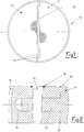
- the tube plate for tube bundles with large sizes is indicated globally by the reference number 10.
- the tube plate 10 has two components, 11 and 12, with a substantially semi-circular shape, which have previously been machined.
- perforated plates can be produced in several pieces or components, according to requirements and to the design dimensions, which are subsequently joined together by means of mechanical joints.
- the components of the tube plate are processed until they are completed, and are then connected mechanically.
- the semi-circular components 11 and 12 are joined to one another by means of a plurality of pins 15.
- the pins 15 are inserted in holes provided respectively in the component 12 and in a projecting portion 13 of the component 11.
- the component 11 has a projection 13 which is inserted in a corresponding cavity 14 in the component 12.
- connection of these components 11 and 12 is completed by means of welded connections 16, between the head of the pin 15 and the component 12, and by means of further welded connections 16' between the components 11 and 12.
- seals of any type can be used, or, alternatively, a welding seal can be produced on the mechanical connection parts (which can consist of braces, screws, wedges, cams etc.).
- the invention makes it possible to process separately and in parallel components with smaller dimensions, on machines with smaller dimensions and capacities.
- the invention avoids the need to use machine tools with large capacities and large useful dimensions, and the time for construction of the manufactured product is reduced.
- the invention can be applied to chemical reactors, heat exchangers, and in general to tube-bundle type pressure devices.
Landscapes
- Chemical & Material Sciences (AREA)
- Organic Chemistry (AREA)
- Chemical Kinetics & Catalysis (AREA)
- Engineering & Computer Science (AREA)
- Physics & Mathematics (AREA)
- Thermal Sciences (AREA)
- Mechanical Engineering (AREA)
- General Engineering & Computer Science (AREA)
- Heat-Exchange Devices With Radiators And Conduit Assemblies (AREA)
- Physical Or Chemical Processes And Apparatus (AREA)
- Organic Low-Molecular-Weight Compounds And Preparation Thereof (AREA)
Description
- The present invention relates to a tube plate for tube bundles for chemical reactors and heat exchangers in general.
- The present invention can also be applied to petrochemical and refinery reactors.
- As is known, chemical reactors consist of containers with large dimensions, inside which chemical reactions take place at a high temperature and a high pressure.
-
- These tube bundles are installed and kept in an operative position by means of use of tube plates, which in some cases can have large dimensions.
- With particular reference to the state of the art, it can be noted that, at present, the tube plates are produced in a single piece, or alternatively in several pieces which are welded together and then finished, for example which are drilled and/or machined.
- However, these processing operations cause some significant technical problems which must be faced satisfactorily.
- Firstly, in order to carry out these processing operations, particular machine tools are necessary, which have large capacities, large useful dimensions, and high costs.
- In addition, the operations to be carried out for these purposes are such that they require processing times which are often too lengthy for present requirements.
- Other problems according to the known art are caused by deformations which are created in the tube plate, as a result of welding shrinkages, in particular in the case of joints which are fully welded.
- The object of the present invention is thus to provide a tube plate for tube bundles for chemical reactors, which eliminates the above-described disadvantages.
- A further object of the present invention is to provide a tube plate for tube bundles for chemical reactors, which can be produced quickly and economically.
- A further object of the present invention is to provide a tube plate for tube bundles for chemical reactors, which is safe and reliable when it is installed.
- These objects and others according to the invention are achieved by a tube plate for holding tube bundles for chemical reactors, said tube plate comprising a first plate component perforated to receive a first plurality of tubes of the bundle and having a projection along a side thereof, a second plate component perforated to receive a second plurality of tubes of the bundle and having a corresponding cavity complementary to the projection for connection to the projection and mechanical joints connecting the projection and corresponding cavity together so that the two plate components form at least a part of the whole tube plate.
- The plate components which form the at least a part of the tube plate may be joined to one another by means of a plurality of pins, which are inserted in corresponding holes provided in the respective components.
- Further characteristics of the tube plate for tube bundles for chemical reactors, according to the present invention, are defined in the other claims attached to the present application.
- The characteristics and advantages of the tube plate for tube bundles for chemical reactors, according to the present invention, will become more apparent from the following description of a typical embodiment, provided by way of non-limiting example, with reference to the attached schematic drawings in which:
-
figure 1 represents in plan view a tube plate for tube bundles for chemical reactors, according to the present invention; and -
figure 2 represents, partially in cross-section, a detail of the system for connection between components of the tube plate in the preceding figure, according to a preferred embodiment of the present invention. - With particular reference to the aforementioned figures, the tube plate for tube bundles with large sizes, according to the present invention, is indicated globally by the
reference number 10. - In the embodiment illustrated by way of example in the attached figures, the
tube plate 10 has two components, 11 and 12, with a substantially semi-circular shape, which have previously been machined. - It will be appreciated that, according to the present invention, perforated plates can be produced in several pieces or components, according to requirements and to the design dimensions, which are subsequently joined together by means of mechanical joints.
- Thus, a perforated plate with large dimensions is produced in several parts which are connected to one another.
- As described briefly hereinafter, the components of the tube plate, the number of which depends on the dimensions and the structural requirements, are processed until they are completed, and are then connected mechanically. In the example illustrated in the attached figures, the
semi-circular components pins 15. - The
pins 15 are inserted in holes provided respectively in thecomponent 12 and in a projectingportion 13 of thecomponent 11. - In fact, the
component 11 has aprojection 13 which is inserted in acorresponding cavity 14 in thecomponent 12. - The connection of these
components welded connections 16, between the head of thepin 15 and thecomponent 12, and by means of further welded connections 16' between thecomponents - However, in addition to the example described, in order to guarantee sealing, seals of any type can be used, or, alternatively, a welding seal can be produced on the mechanical connection parts (which can consist of braces, screws, wedges, cams etc.).
- As a result, the invention makes it possible to process separately and in parallel components with smaller dimensions, on machines with smaller dimensions and capacities.
- The description provided makes apparent the characteristics and technical advantages of the tube plate for tube bundles for chemical reactors, according to the present invention.
- The following considerations and concluding comments are now made, in order to define the said advantages more clearly and accurately.
- The invention avoids the need to use machine tools with large capacities and large useful dimensions, and the time for construction of the manufactured product is reduced.
- In addition, there is a drastic reduction in the problems of deformation caused by welding shrinkages, in the case of fully welded joints.
- The invention can be applied to chemical reactors, heat exchangers, and in general to tube-bundle type pressure devices.
- Finally, it is apparent that many other variations can be made to the tube plate or tube bundles for chemical reactors which is the subject of the present invention, and that, in the practical implementation of the invention, any materials, dimensions and forms can be used according to requirements.
Claims (4)
- Tube plate (10) for holding tube bundles for chemical reactors, said tube plate constituted by means of a pair of semi-circular plate components which are joined to one another along a median line and comprising
a first plate component (11) perforated to receive a first plurality of tubes of the bundle and having a projection (13) along a side thereof,
a second plate component (12) perforated to receive a second plurality of tubes of the bundle and having a corresponding cavity (14) to the projection (13) for connection to the projection (13), and
a plurality of pins (15) connecting the projection and corresponding cavity (13, 14) together so that the two plate components (11,12) form the whole tube plate (10),
wherein the plurality of pins (15) are inserted in corresponding holes provided in the respective components (11, 12). - Tube plate (10) according to claim 1, wherein at least one the said first plate components (11, 12), has a series of projections (13), which are inserted in corresponding cavities (14) in the respective component, such as to enable the said pins (15) to pass through the cavities (14) and the projections (13) to complete the connection between the said components (11, 12).
- Tube plate (10) according to claim 2, wherein the connection of the plate components (11, 12) is completed by means of welded connections (16) between the head of the said pins (15) and at least one of the plate components (11, 12).
- Tube plate (10) according to claim 2, wherein the connection of the plate components (11, 12) is completed by means of welded connections (16') between the plate components (11, 12).
Applications Claiming Priority (2)
| Application Number | Priority Date | Filing Date | Title |
|---|---|---|---|
| ITMI002594 | 2000-11-30 | ||
| IT2000MI002594A IT1319494B1 (en) | 2000-11-30 | 2000-11-30 | TUBE PLATE FOR TUBE BANDS FOR CHEMICAL REACTORS AND HEAT EXCHANGERS IN GENERAL |
Publications (3)
| Publication Number | Publication Date |
|---|---|
| EP1210976A2 EP1210976A2 (en) | 2002-06-05 |
| EP1210976A3 EP1210976A3 (en) | 2004-01-28 |
| EP1210976B1 true EP1210976B1 (en) | 2019-10-09 |
Family
ID=11446153
Family Applications (1)
| Application Number | Title | Priority Date | Filing Date |
|---|---|---|---|
| EP01310032.6A Expired - Lifetime EP1210976B1 (en) | 2000-11-30 | 2001-11-30 | Tube plate for tube bundles for chemical reactors and heat exchangers in general |
Country Status (9)
| Country | Link |
|---|---|
| US (1) | US6869247B2 (en) |
| EP (1) | EP1210976B1 (en) |
| JP (1) | JP3984036B2 (en) |
| KR (1) | KR100622787B1 (en) |
| CN (1) | CN100408964C (en) |
| CA (1) | CA2363331C (en) |
| IT (1) | IT1319494B1 (en) |
| RO (1) | RO118606B1 (en) |
| RU (1) | RU2293272C2 (en) |
Families Citing this family (3)
| Publication number | Priority date | Publication date | Assignee | Title |
|---|---|---|---|---|
| DE102007024934B4 (en) | 2007-05-29 | 2010-04-29 | Man Dwe Gmbh | Tube bundle reactors with pressure fluid cooling |
| CN105921096B (en) * | 2016-06-06 | 2018-04-10 | 大连理工大学 | A kind of folding piecemeal column plate attachment structure |
| RU2738095C1 (en) * | 2019-12-25 | 2020-12-08 | Артем Борисович Касимовский | Shell-and-tube repair heat exchanger |
Family Cites Families (18)
| Publication number | Priority date | Publication date | Assignee | Title |
|---|---|---|---|---|
| US2858582A (en) * | 1953-12-01 | 1958-11-04 | Ohio Commw Eng Co | Building material |
| US4134451A (en) | 1976-12-23 | 1979-01-16 | Conant Louis A | Heat exchanger elements and other chemical processing elements comprising metal coated, heat stabilized impervious graphite |
| US4206802A (en) | 1978-03-27 | 1980-06-10 | General Electric Company | Moisture separator reheater with thermodynamically enhanced means for substantially eliminating condensate subcooling |
| US4223722A (en) | 1978-10-02 | 1980-09-23 | General Electric Company | Controllable inlet header partitioning |
| SE414660B (en) * | 1978-11-13 | 1980-08-11 | Braxell N | DEVICE FOR COATING PARTS |
| US4246872A (en) | 1979-04-30 | 1981-01-27 | General Electric Company | Heat exchanger tube support |
| DE69000306T2 (en) | 1989-02-17 | 1993-02-25 | Jgc Corp | TUBE BUNDLE APPARATUS WITH AN INTERMEDIATE TUBE PLATE. |
| FR2645941A1 (en) | 1989-04-14 | 1990-10-19 | Procedes Petroliers Petrochim | Device for linking a metallic support to a tubular element made from a refractory material of the ceramic type, and hydrocarbon pyrolysis plant comprising such elements and their linking devices |
| US5472928A (en) | 1989-07-19 | 1995-12-05 | Scheuerman; Georgieanna L. | Catalyst, method and apparatus for an on-stream particle replacement system for countercurrent contact of a gas and liquid feed stream with a packed bed |
| SU1661562A1 (en) * | 1989-07-24 | 1991-07-07 | Предприятие П/Я А-7755 | Header chamber of heat exchanger |
| RU2037122C1 (en) * | 1993-02-03 | 1995-06-09 | Пермское предприятие "ФЭН" (ТОО) | Vertical case-pipe heat exchanger |
| JP3125834B2 (en) * | 1993-09-01 | 2001-01-22 | 株式会社デンソー | Heat exchanger and method of manufacturing the same |
| DE19501276C2 (en) | 1995-01-18 | 2000-03-16 | Rosink App & Anlagenbau Gmbh | Pipe bundles for boiler heat exchangers and heat exchangers with pipe bundles and process for the production of pipe bundles |
| US5709500A (en) * | 1995-04-25 | 1998-01-20 | Mizelle; Ned W. | Furniture, furniture manufacturing method, and connector assembly |
| US5862975A (en) * | 1996-03-20 | 1999-01-26 | The Boeing Company | Composite/metal structural joint with welded Z-pins |
| DE19714423C2 (en) * | 1997-04-08 | 2003-05-08 | Schnabel Gmbh & Co Kg Dr | Shell and tube heat exchangers |
| JP3589863B2 (en) * | 1997-07-23 | 2004-11-17 | 株式会社日立製作所 | Structure and friction stir welding method |
| US6530719B1 (en) * | 2000-07-21 | 2003-03-11 | George V. Stephan | Gripping and maneuvering apparatus |
-
2000
- 2000-11-30 IT IT2000MI002594A patent/IT1319494B1/en active
-
2001
- 2001-11-15 CA CA002363331A patent/CA2363331C/en not_active Expired - Lifetime
- 2001-11-21 US US09/989,132 patent/US6869247B2/en not_active Expired - Lifetime
- 2001-11-27 RO ROA200101277A patent/RO118606B1/en unknown
- 2001-11-29 KR KR1020010074968A patent/KR100622787B1/en not_active Expired - Lifetime
- 2001-11-29 RU RU2001132491/06A patent/RU2293272C2/en active
- 2001-11-29 JP JP2001363610A patent/JP3984036B2/en not_active Expired - Lifetime
- 2001-11-30 EP EP01310032.6A patent/EP1210976B1/en not_active Expired - Lifetime
- 2001-11-30 CN CNB011429585A patent/CN100408964C/en not_active Expired - Lifetime
Non-Patent Citations (1)
| Title |
|---|
| None * |
Also Published As
| Publication number | Publication date |
|---|---|
| EP1210976A3 (en) | 2004-01-28 |
| RO118606B1 (en) | 2003-07-30 |
| KR20020042498A (en) | 2002-06-05 |
| IT1319494B1 (en) | 2003-10-20 |
| RU2293272C2 (en) | 2007-02-10 |
| ITMI20002594A1 (en) | 2002-05-30 |
| CA2363331C (en) | 2008-01-29 |
| US20020062952A1 (en) | 2002-05-30 |
| JP2002327997A (en) | 2002-11-15 |
| CN100408964C (en) | 2008-08-06 |
| JP3984036B2 (en) | 2007-09-26 |
| US6869247B2 (en) | 2005-03-22 |
| KR100622787B1 (en) | 2006-09-13 |
| CN1356526A (en) | 2002-07-03 |
| EP1210976A2 (en) | 2002-06-05 |
| CA2363331A1 (en) | 2002-05-30 |
Similar Documents
| Publication | Publication Date | Title |
|---|---|---|
| EP0177045B1 (en) | Bladder mandrel for hydraulic expansions of tubes and sleeves | |
| US6155339A (en) | Obround header for a heat exchanger | |
| CN102575905B (en) | Method for producing heat exchanger plate bundles | |
| EP3964322B1 (en) | Device and method for restoring the tube-to-tube sheet weld joints in a shell-and-tube heat exchanger | |
| JP4602714B2 (en) | Heat exchanger | |
| US4724293A (en) | Method of making a pressure vessel | |
| US5214848A (en) | Method for making a tube for a heat exchanger | |
| US6869247B2 (en) | Tube plate for tube bundles for chemical reactors and heat exchangers in general | |
| EP2479875A2 (en) | Liquid cooled housing with bearing shield for electrical machine | |
| US4724595A (en) | Bladder mandrel for hydraulic expansions of tubes and sleeves | |
| US2844360A (en) | Heat exchanger | |
| JP2008051237A (en) | Connecting structure of for a plurality of pipes | |
| EP0408377A2 (en) | Filter assembly | |
| JP2005014060A (en) | Pipe bending metal core and pipe bending method | |
| EP0630704A1 (en) | Improved process and system for the production of elements for column radiators | |
| JPS5844199B2 (en) | Multi-tube heat exchanger that can be blind plugged by welding | |
| RU2001132491A (en) | Tube grating for tube bundles for chemical reactors | |
| JPS591065A (en) | Welding of long member | |
| JP7319139B2 (en) | Piping structure and heat exchanger | |
| JP3640496B2 (en) | Repair method for plate heat exchanger | |
| JPH10332294A (en) | Tube for heat exchanger | |
| WO2023053555A1 (en) | Method for dismantling steam generator | |
| JPH04327794A (en) | Method for mounting plate coil of heat exchanger | |
| CN119238044A (en) | A welding manufacturing method for a large hemispherical head made of high chromium-molybdenum steel | |
| CN116000154A (en) | Connection structure of Z-shaped section bar and stretch bending die machine tool |
Legal Events
| Date | Code | Title | Description |
|---|---|---|---|
| PUAI | Public reference made under article 153(3) epc to a published international application that has entered the european phase |
Free format text: ORIGINAL CODE: 0009012 |
|
| AK | Designated contracting states |
Kind code of ref document: A2 Designated state(s): AT BE CH CY DE DK ES FI FR GB GR IE IT LI LU MC NL PT SE TR |
|
| AX | Request for extension of the european patent |
Free format text: AL;LT;LV;MK;RO;SI |
|
| PUAL | Search report despatched |
Free format text: ORIGINAL CODE: 0009013 |
|
| AK | Designated contracting states |
Kind code of ref document: A3 Designated state(s): AT BE CH CY DE DK ES FI FR GB GR IE IT LI LU MC NL PT SE TR |
|
| AX | Request for extension of the european patent |
Extension state: AL LT LV MK RO SI |
|
| 17P | Request for examination filed |
Effective date: 20040728 |
|
| AKX | Designation fees paid |
Designated state(s): DE ES FR |
|
| 17Q | First examination report despatched |
Effective date: 20100503 |
|
| GRAP | Despatch of communication of intention to grant a patent |
Free format text: ORIGINAL CODE: EPIDOSNIGR1 |
|
| INTG | Intention to grant announced |
Effective date: 20181218 |
|
| RIC1 | Information provided on ipc code assigned before grant |
Ipc: F28F 9/02 20060101ALI20020418BHEP Ipc: B01J 8/00 20060101ALI20020418BHEP Ipc: B01J 8/06 20060101AFI20020418BHEP |
|
| GRAS | Grant fee paid |
Free format text: ORIGINAL CODE: EPIDOSNIGR3 |
|
| GRAA | (expected) grant |
Free format text: ORIGINAL CODE: 0009210 |
|
| AK | Designated contracting states |
Kind code of ref document: B1 Designated state(s): DE ES FR |
|
| REG | Reference to a national code |
Ref country code: DE Ref legal event code: R096 Ref document number: 60151196 Country of ref document: DE |
|
| PG25 | Lapsed in a contracting state [announced via postgrant information from national office to epo] |
Ref country code: ES Free format text: LAPSE BECAUSE OF FAILURE TO SUBMIT A TRANSLATION OF THE DESCRIPTION OR TO PAY THE FEE WITHIN THE PRESCRIBED TIME-LIMIT Effective date: 20191009 |
|
| REG | Reference to a national code |
Ref country code: DE Ref legal event code: R097 Ref document number: 60151196 Country of ref document: DE |
|
| PLBE | No opposition filed within time limit |
Free format text: ORIGINAL CODE: 0009261 |
|
| STAA | Information on the status of an ep patent application or granted ep patent |
Free format text: STATUS: NO OPPOSITION FILED WITHIN TIME LIMIT |
|
| 26N | No opposition filed |
Effective date: 20200710 |
|
| PG25 | Lapsed in a contracting state [announced via postgrant information from national office to epo] |
Ref country code: FR Free format text: LAPSE BECAUSE OF NON-PAYMENT OF DUE FEES Effective date: 20191209 |
|
| PGFP | Annual fee paid to national office [announced via postgrant information from national office to epo] |
Ref country code: DE Payment date: 20201020 Year of fee payment: 20 |
|
| REG | Reference to a national code |
Ref country code: DE Ref legal event code: R071 Ref document number: 60151196 Country of ref document: DE |