EP1210975B1 - Knochenzementmischvorrichtung mit Getriebeanordnung zum Antrieb einer Mischschaufel - Google Patents
Knochenzementmischvorrichtung mit Getriebeanordnung zum Antrieb einer Mischschaufel Download PDFInfo
- Publication number
- EP1210975B1 EP1210975B1 EP01310078A EP01310078A EP1210975B1 EP 1210975 B1 EP1210975 B1 EP 1210975B1 EP 01310078 A EP01310078 A EP 01310078A EP 01310078 A EP01310078 A EP 01310078A EP 1210975 B1 EP1210975 B1 EP 1210975B1
- Authority
- EP
- European Patent Office
- Prior art keywords
- gear
- mixing
- rotation
- input gear
- input
- Prior art date
- Legal status (The legal status is an assumption and is not a legal conclusion. Google has not performed a legal analysis and makes no representation as to the accuracy of the status listed.)
- Expired - Lifetime
Links
Images


Classifications
-
- B—PERFORMING OPERATIONS; TRANSPORTING
- B01—PHYSICAL OR CHEMICAL PROCESSES OR APPARATUS IN GENERAL
- B01F—MIXING, e.g. DISSOLVING, EMULSIFYING OR DISPERSING
- B01F33/00—Other mixers; Mixing plants; Combinations of mixers
- B01F33/50—Movable or transportable mixing devices or plants
- B01F33/501—Movable mixing devices, i.e. readily shifted or displaced from one place to another, e.g. portable during use
- B01F33/5011—Movable mixing devices, i.e. readily shifted or displaced from one place to another, e.g. portable during use portable during use, e.g. hand-held
-
- B—PERFORMING OPERATIONS; TRANSPORTING
- B01—PHYSICAL OR CHEMICAL PROCESSES OR APPARATUS IN GENERAL
- B01F—MIXING, e.g. DISSOLVING, EMULSIFYING OR DISPERSING
- B01F27/00—Mixers with rotary stirring devices in fixed receptacles; Kneaders
- B01F27/80—Mixers with rotary stirring devices in fixed receptacles; Kneaders with stirrers rotating about a substantially vertical axis
- B01F27/90—Mixers with rotary stirring devices in fixed receptacles; Kneaders with stirrers rotating about a substantially vertical axis with paddles or arms
- B01F27/906—Mixers with rotary stirring devices in fixed receptacles; Kneaders with stirrers rotating about a substantially vertical axis with paddles or arms with fixed axis
-
- B—PERFORMING OPERATIONS; TRANSPORTING
- B01—PHYSICAL OR CHEMICAL PROCESSES OR APPARATUS IN GENERAL
- B01F—MIXING, e.g. DISSOLVING, EMULSIFYING OR DISPERSING
- B01F35/00—Accessories for mixers; Auxiliary operations or auxiliary devices; Parts or details of general application
- B01F35/30—Driving arrangements; Transmissions; Couplings; Brakes
- B01F35/33—Transmissions; Means for modifying the speed or direction of rotation
-
- A—HUMAN NECESSITIES
- A61—MEDICAL OR VETERINARY SCIENCE; HYGIENE
- A61B—DIAGNOSIS; SURGERY; IDENTIFICATION
- A61B50/00—Containers, covers, furniture or holders specially adapted for surgical or diagnostic appliances or instruments, e.g. sterile covers
- A61B2050/005—Containers, covers, furniture or holders specially adapted for surgical or diagnostic appliances or instruments, e.g. sterile covers with a lid or cover
- A61B2050/0062—Containers, covers, furniture or holders specially adapted for surgical or diagnostic appliances or instruments, e.g. sterile covers with a lid or cover closable by a combination of rotation and translation
- A61B2050/0064—Containers, covers, furniture or holders specially adapted for surgical or diagnostic appliances or instruments, e.g. sterile covers with a lid or cover closable by a combination of rotation and translation by screwing
-
- A—HUMAN NECESSITIES
- A61—MEDICAL OR VETERINARY SCIENCE; HYGIENE
- A61F—FILTERS IMPLANTABLE INTO BLOOD VESSELS; PROSTHESES; DEVICES PROVIDING PATENCY TO, OR PREVENTING COLLAPSING OF, TUBULAR STRUCTURES OF THE BODY, e.g. STENTS; ORTHOPAEDIC, NURSING OR CONTRACEPTIVE DEVICES; FOMENTATION; TREATMENT OR PROTECTION OF EYES OR EARS; BANDAGES, DRESSINGS OR ABSORBENT PADS; FIRST-AID KITS
- A61F2/00—Filters implantable into blood vessels; Prostheses, i.e. artificial substitutes or replacements for parts of the body; Appliances for connecting them with the body; Devices providing patency to, or preventing collapsing of, tubular structures of the body, e.g. stents
- A61F2/02—Prostheses implantable into the body
- A61F2/30—Joints
- A61F2002/30001—Additional features of subject-matter classified in A61F2/28, A61F2/30 and subgroups thereof
- A61F2002/30003—Material related properties of the prosthesis or of a coating on the prosthesis
- A61F2002/3006—Properties of materials and coating materials
- A61F2002/3009—Transparent or translucent
-
- A—HUMAN NECESSITIES
- A61—MEDICAL OR VETERINARY SCIENCE; HYGIENE
- A61F—FILTERS IMPLANTABLE INTO BLOOD VESSELS; PROSTHESES; DEVICES PROVIDING PATENCY TO, OR PREVENTING COLLAPSING OF, TUBULAR STRUCTURES OF THE BODY, e.g. STENTS; ORTHOPAEDIC, NURSING OR CONTRACEPTIVE DEVICES; FOMENTATION; TREATMENT OR PROTECTION OF EYES OR EARS; BANDAGES, DRESSINGS OR ABSORBENT PADS; FIRST-AID KITS
- A61F2/00—Filters implantable into blood vessels; Prostheses, i.e. artificial substitutes or replacements for parts of the body; Appliances for connecting them with the body; Devices providing patency to, or preventing collapsing of, tubular structures of the body, e.g. stents
- A61F2/02—Prostheses implantable into the body
- A61F2/30—Joints
- A61F2/46—Special tools or methods for implanting or extracting artificial joints, accessories, bone grafts or substitutes, or particular adaptations therefor
- A61F2002/4685—Special tools or methods for implanting or extracting artificial joints, accessories, bone grafts or substitutes, or particular adaptations therefor by means of vacuum
-
- A—HUMAN NECESSITIES
- A61—MEDICAL OR VETERINARY SCIENCE; HYGIENE
- A61F—FILTERS IMPLANTABLE INTO BLOOD VESSELS; PROSTHESES; DEVICES PROVIDING PATENCY TO, OR PREVENTING COLLAPSING OF, TUBULAR STRUCTURES OF THE BODY, e.g. STENTS; ORTHOPAEDIC, NURSING OR CONTRACEPTIVE DEVICES; FOMENTATION; TREATMENT OR PROTECTION OF EYES OR EARS; BANDAGES, DRESSINGS OR ABSORBENT PADS; FIRST-AID KITS
- A61F2250/00—Special features of prostheses classified in groups A61F2/00 - A61F2/26 or A61F2/82 or A61F9/00 or A61F11/00 or subgroups thereof
- A61F2250/0058—Additional features; Implant or prostheses properties not otherwise provided for
- A61F2250/0091—Additional features; Implant or prostheses properties not otherwise provided for transparent or translucent
-
- B—PERFORMING OPERATIONS; TRANSPORTING
- B01—PHYSICAL OR CHEMICAL PROCESSES OR APPARATUS IN GENERAL
- B01F—MIXING, e.g. DISSOLVING, EMULSIFYING OR DISPERSING
- B01F2101/00—Mixing characterised by the nature of the mixed materials or by the application field
- B01F2101/20—Mixing of ingredients for bone cement
-
- B—PERFORMING OPERATIONS; TRANSPORTING
- B01—PHYSICAL OR CHEMICAL PROCESSES OR APPARATUS IN GENERAL
- B01F—MIXING, e.g. DISSOLVING, EMULSIFYING OR DISPERSING
- B01F35/00—Accessories for mixers; Auxiliary operations or auxiliary devices; Parts or details of general application
- B01F35/30—Driving arrangements; Transmissions; Couplings; Brakes
- B01F35/32—Driving arrangements
- B01F35/32005—Type of drive
- B01F35/3202—Hand driven
Definitions
- the present invention relates generally to a surgical assembly, and more particularly to an apparatus for mixing bone cement.
- cement or grouting type agent such as for attaching artificial joint implants, repairing or forming joints in bones, or other forms of orthopaedic work.
- the type of cement generally used for these purposes is a self-curing resin formed from the blending of a wide variety of liquid monomers or co-monomers with powdered polymers or copolymers to form a viscous admixture to be used as the grouting agent.
- the admixture of the powder and liquid components develops a quick setting material.
- preparation of the cement usually occurs directly within the operating area just prior to use.
- a bone cement mixing apparatus is generally utilized to mix the powder and liquid components in the operating area.
- the resultant admixture is then removed from the mixing apparatus and placed in a cement delivery apparatus for subsequent use by the surgeon.
- the bone cement must generally first be scooped or otherwise removed from the mixing apparatus and thereafter placed in a syringe-type delivery apparatus for use by the surgeon.
- the system described above for mixing and delivering bone cement has a number of drawbacks associated therewith.
- monomer vapours are generated during the depositing of the monomer into the mixing apparatus and during the subsequent mixing of the monomer with the powder component of the bone cement.
- Such monomer vapours may be noxious and/or toxic.
- the bone cement is generally mixed in the operating room environment, it is important to prevent any monomer or its vapours from escaping the mixing apparatus.
- heretofore designed mixing apparatus have not included mechanisms for controlling the escape of such vapours.
- heretofore designed mixing apparatus have been plagued with problems relating to the incomplete mixing of the liquid component and the powder component. Specifically, the powder component and liquid component are often inadequately mixed during operation of heretofore designed systems. Such a problem is further compounded by the fact that heretofore designed mixing vessels are not transparent thereby preventing the contents of the vessel (i.e. the bone cement) from being viewed by the operator of the mixing apparatus.
- the system described above also suffers from operational inefficiencies relating to the need to transfer the mixed bone cement from the mixing apparatus to the delivery apparatus.
- the need to remove the mixed bone cement from one device (i.e. the mixing apparatus) and place it in a second device (i.e. the delivery device) creates an extra step in the process thereby increasing the time necessary to deliver the mixed bone cement.
- a quantity of the bone cement is lost in the process since it is highly unlikely that all of the mixed cement is actually removed from the mixing apparatus and placed in the delivery apparatus.
- WO 95/13862 discusses a manual bone cement mixing system.
- the system includes a rotary mixer with a pair of spaced mixing arms.
- the mixer mixes dry PMMA powder and MMA liquid in a vacuum chamber.
- the mixing arms follow a path with a plurality of loops, and rotate in a sense determined by the direction of rotation of a crank arm.
- FR-711436 relates to a reciprocating drive applied to a washing machine.
- the reciprocating motion is achieved by the alternate engagement of two separate sets of teeth on a rotating plate with a gear attached to a shaft for connection with a washing machine.
- What is needed therefore is an apparatus and method for mixing a bone cement which overcomes one or more of the above-mentioned drawbacks. What is particularly needed is an apparatus and method for mixing bone cement which reduces, if not eliminates, exposure to vapours from the liquid bone cement component within the operating area. What is further needed is an apparatus and method for mixing bone cement which may also be utilized to delivery the mixed bone cement. What is moreover needed is an apparatus and method for mixing bone cement which reduces, or even eliminates, the occasions in which a portion of the powder cement component is not thoroughly mixed with the liquid cement component.
- a bone cement mixing apparatus which includes a handle.
- the bone cement mixing apparatus further includes an input gear which is caused to rotate about a central axis in response to rotation of the handle, wherein (i) the input gear includes a first input gear teeth set and a second input gear teeth set, (ii) the first input gear teeth set is spaced a first radial distance from the central axis, (iii) the second input gear teeth set is spaced a second radial distance from the central axis, (iv) the second radial distance is greater than the first radial distance, (v) the first input gear teeth set extends outwardly away from the central axis, and (vi) the second input gear teeth set extends inwardly toward the central axis.
- the bone cement mixing apparatus additionally includes an intermediate gear, wherein the input gear is configured so that during rotation thereof (I) the first input gear teeth set meshingly engages the intermediate gear during a first period of time, and (ii) the second input gear teeth set meshingly engages the intermediate gear during a second period of time which is different from the first period of time.
- the bone cement mixing apparatus also includes an output gear which is caused to rotate in response to rotation of the intermediate gear. Further, the bone cement mixing apparatus includes a mixing blade which is caused to rotate in response to rotation of the output gear.
- the bone cement mixing device may have a canister which is modular in design and constructed from a transparent material.
- the mixing device may further have a mixing head assembly having a crank which is operatively coupled to a mixing blade via a gear train.
- the gear train may be configured to drive the mixing blade in a reciprocating manner including the varying of the angular velocity, direction of travel, and angular distance of travel of the blade while the crank is rotated at a constant velocity and direction.
- the mixing blade may have a fluid passage defined therein which allows the liquid cement component to be delivered at various locations within the mixing chamber of the canister.
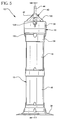
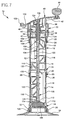
- FIGS. 1-7 show a bone cement mixing device 10 which is configured to receive a quantity of a powder bone cement component and a liquid bone cement component (e.g. a monomer) and thereafter mix the powder component and liquid component together.
- the bone cement mixing device 10 is also operable as a bone cement delivery device thereby eliminating the need to utilize a separate delivery device.
- the mixing device 10 includes a canister 12 having a mixing chamber 14 defined therein.
- the canister 12 is preferably embodied as a pair of identical cylindrically-shaped cartridges 16, 18. Use of the cartridges 16, 18 allows for modular construction of the mixing device 10 while also reducing the number of different components which are utilized in the design thereof.
- Each of the cartridges 16, 18 is preferably constructed of a transparent material such as a transparent plastic material.
- a transparent material such as a transparent plastic material.
- Such use of a transparent material in the construction of the cartridges 16, 18 is advantageous in that the operator the mixing device may visually observe the contents within the mixing chamber 14 (i.e. the powder and liquid cement components) in order to visually determine if the components have been adequately (i.e. thoroughly) mixed with one another.
- the cartridges 16, 18 may be constructed to accommodate any quantity of bone cement.
- the cartridges 16, 18 are constructed to hold and mix at least 120 grams of powder bone cement component and the associated quantity of the liquid bone cement component (i.e. the monomer).
- Such a configuration is advantageous in that surgical procedures commonly require the preparation of three (3) batches of bone cement powder (with each batch being 40 grams). It is often necessary when using a heretofore designed mixing apparatus for each of the three batches to be prepared (i.e. mixed) separately thereby potentially creating delays and/or timing difficulties within the operating area during a surgical procedure.
- the mixing device 10 of the present invention overcomes this limitation by being configured to mix all three of the batches simultaneously.
- the upper end 20 of each of the cartridges 16, 18 has a first number of threads 22 defined therein, whereas the lower end 24 of each of the cartridges 16, 18 has a corresponding number of threads 26 defined therein.
- the threads 22, 26 may be threadingly engaged with one another (as in the case of the junction between the cartridges 16, 18), or may be engaged to a number of other components.
- the threads 22 of the upper end 20 of the cartridge 16 are threadingly engaged with a number of threads 28 associated with a mixing head assembly 30.
- the threads 26 of the lower end 24 of the canister 18, on the other hand, are threadingly engaged with a number of threads 32 defined in a base 34.
- sealing members such as O-rings 158 (see FIGS. 7, 9, and 23) are preferably utilized at each threaded coupling (i.e. between the cartridges 16, 18, between the cartridge 16 and the mixing head assembly 30, and between the cartridge 18 and the base 34).
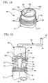
- the mixing head assembly 30 includes an upper gear housing 36 and a lower gear housing 38.
- the upper gear housing 36 is press fit or otherwise secured to the lower gear housing 38.
- the mixing head assembly 30 also includes a crank 40 which is rotatably secured to the upper gear housing 36.
- the crank 40 includes an elongated arm 42 having a knob 44 rotatably secured to an end thereof.
- the upper gear housing 36 and the lower gear housing 38 cooperate to house a gear train 46 which is driven by rotation of the crank 40.
- the gear train 46 includes an output pinion 48 which is rotatably coupled to the lower gear housing 38.
- the output pinion 48 includes a downwardly extending coupling portion 50 which extends through an aperture 51 defined in the lower gear housing 38 (see also FIG. 13).
- the coupling portion 50 of the output pinion 48 is non-rotatably secured to an upper end 106 of a mixing blade 52.
- the coupling portion 50 of the output pinion 48 includes a number of barbs 58 which are received into a corresponding number of slots 60 (see FIGS. 7 and 9) defined in a coupling portion 108 of the mixing blade 52.
- rotation of the output pinion 48 causes similar rotation (i.e. in the same direction and at the same angular velocity) of the mixing blade 52.
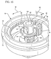
- the mixing head assembly 30 is shown in greater detail.
- the mixing head assembly 30 also includes a directional gear 54, an idler gear 56, and the output pinion 48.
- the directional gear 54, the idler gear 56, and the output pinion 48 are housed within the housing defined by the upper gear housing 36 and the lower gear housing 38.
- the output pinion 48 has a shoulder 60 defined therein.
- the shoulder 60 of the output pinion 48 contacts a retaining surface 62 of the gear housing 38 (see FIG. 13) thereby retaining the output opinion 48 while also allowing it to rotate relative to the gear housing 38.
- the idler gear 56 has an aperture 64 defined therein (see FIG. 12) which is received around a post 66 (see FIGS. 13 and 14) defined in the lower gear housing 38 thereby rotatably securing the idler gear 56 to the lower gear housing 38.
- the other end of the idler gear 56 has a post 68 extending therefrom which is received into a slot 70 defined in the body 72 of the directional gear 54 (see FIGS. 10 and 17).
- the post 68 is captured by or is otherwise retained within the slot 70 during rotation of the directional gear 54.
- the directional gear 54 is non-rotatably secured to the crank 40 by use of a hexagonally-shaped coupling mechanism 74.
- the crank 40 has a hexagonally-shaped member 76 extending downwardly therefrom, whereas the body 72 of the directional gear 54 has a slightly larger hexagonally-shaped member 78 extending upwardly therefrom.
- a shoulder 80 of the crank is positioned in contact which a bearing surface 82 defined on the upper surface of the upper gear housing 36 (see FIG. 13) thereby allowing the hexagonally-shaped member 76 of the crank 40 to extend through a housing opening 84 defined in the upper gear housing 36.
- the hexagonally-shaped member 76 of the crank 40 may be press fit or otherwise received into the hexagonally-shaped member 78 of the directional gear 54 which is positioned within the upper gear housing 36 (see FIG. 11).
- rotation of the crank 40 relative to the upper gear housing 36 causes similar rotation of the directional gear 54 relative to the upper gear housing 36.
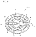
- the directional gear 54 is caused to rotate about a central axis CA as shown in FIG 17.
- the idler gear 56 is meshingly engaged with both the directional gear 54 and the output pinion 48.
- the directional gear 54 includes a first number of gear teeth 86 defined in the body 72 thereof.
- the gear teeth 86 are positioned around a portion of the periphery of an aperture 88 which defines the axis of rotation of the directional gear 54.
- the directional gear 54 also includes a second number of gear teeth 90 defined in the body 72 thereof.
- the gear teeth 90 are spaced radially outwardly from the gear teeth 86.
- the gear teeth 86 and the gear teeth 90 selectively meshingly engage with the idler gear 56 so as to selectively drive the output pinion 48 (and hence the mixing blade 52) at varying velocities and directions of rotation.
- the central axis CA lies in a plane P which divides the directional gear 54 into a first directional gear side and a second directional gear side (see e.g. FIG. 17).
- the directional gear 54 is configured so that (i) the gear teeth 86 are positioned entirely on the first input gear side, and (ii) the gear teeth 90 are positioned entirely on the second input gear side as shown in FIG. 17.
- the idler gear 56 has a number of gear teeth 92 defined therein, whereas the output pinion 48 has a number of gear teeth 94 defined therein.
- the gear teeth 92 of the idler gear 56 are meshingly engaged with the gear teeth 94 of the output pinion 48.
- rotation of the idler gear 56 in a given direction causes rotation of the output pinion 48 in the opposite direction.
- clockwise rotation of the idler gear 56 causes counterclockwise rotation of the output pinion 48, and vice versa.
- the gear teeth 92 of the idler gear 56 are engaged by either the inner gear teeth 86 or the outer gear teeth 90 of the directional gear 54 during rotation of the directional gear 54.
- the idler gear 56 is initially engaged by the outer gear teeth 90 of the directional gear 54 thereby causing the idler gear 56 to likewise be rotated in the counterclockwise direction (as indicated by the arrow 96).
- Rotation of the idler gear 56 in the counterclockwise direction causes rotation of the output pinion 48 (and hence the mixing blade 52) in the opposite direction (i.e. in a clockwise rotation as viewed from the bottom perspective view of FIGS. 15-17 and designated by the arrow 98).
- crank 40 is rotated in the opposite direction (i.e. so as to cause rotation of the directional gear 54 in the clockwise direction as viewed in FIGS. 15-17 and indicated by arrow 98)
- the idler gear 56 and the output pinion 48 are rotated in the respective opposite directions to that as described above.
- rotation of the directional gear 54 in the clockwise direction i.e. in the direction of arrow 98 of FIGS. 15-17
- rotation of the directional gear 54 in the clockwise direction causes (1) clockwise rotation of the idler gear 56, and (2) counterclockwise rotation of the output pinion 48 (and hence the mixing blade 52) when the idler gear 56 is meshingly engaged with the outer gear teeth 90.
- rotation of the directional gear 54 in the clockwise direction i.e.
- the gear train 46 of the present invention is configured such that the direction of rotation of the output pinion 48 changes despite rotation of the crank 40 in only a single direction. Specifically, as the idler gear 56 is engaged with the outer gear teeth 90, the output pinion 48 and hence the mixing blade 52 is rotated in a first direction. However, as the idler gear 56 disengages the outer gear teeth 90 and engages the inner gear teeth 86, the direction of travel of the output pinion 48 and hence the mixing blade 52 is reversed thereby creating alternating or reciprocating motion.
- the relatively large number of individual gear teeth associated with the outer gear teeth 90 creates a relatively large gear ratio with the idler gear 56 relative to the gear ratio created by inner gear teeth 86 and the idler gear 56, varying angular distances of travel and speeds of the mixing blade 52 are created.
- the relatively high gear ratio created by the outer gear teeth 90 causes the output pinion 48 to be driven across a greater angular distance when the idler gear 56 is engaged with the outer gear teeth 90 relative to the angular distance across which the output pinion 48 is driven when the idler gear 56 is engaged with the inner gear teeth 86.
- the output pinion 48 (and hence the mixing blade 52) is driven across 540° of rotation when the idler gear 56 is engaged with the outer drive teeth 90, whereas the output pinion (and hence the mixing blade 52) is only advanced across 135° of rotation (in the opposite direction) when the idler gear 56 is engaged with the inner drive teeth 86.
- the mixing blade 52 is driven across 540° of rotation in a first direction and then reversed and driven across 135° of rotation in the opposite direction.
- the relatively high gear ratio created by the outer gear teeth 90 also causes the output pinion 48 to be driven at a greater angular velocity when the idler gear 56 is engaged with the outer gear teeth 90 relative to the angular velocity at which the output pinion 48 is driven when the idler gear 56 is engaged with the inner gear teeth 86.
- the output pinion 48 (and hence the mixing blade 52) is driven at a velocity which is approximately three times greater than the velocity at which the output pinion 48 (and hence the mixing blade 52) is driven when the idler gear 56 is engaged with the inner drive teeth 86.
- the mixing blade 52 is driven three times as quickly in the first direction as it is when reversed and driven in the opposite direction.
- the configuration of the directional gear 54 described herein is exemplary in nature and may be altered to fit the requirements of a given design of the mixing device 10.
- the number of teeth included in the gear teeth 86 and 90 may be varied in order to produce a desired gear ratio. Such modification to the gear teeth 86 and 90 would allow for modification to the angular distance and speed at which the mixing blade 52 is driven during rotation of the crank 40 by the operator.
- the drive characteristics of the mixing head assembly 30 provide numerous advantages to the mixing device 10 of the present invention relative to heretofore designed mixing devices.
- the reciprocating movement of the mixing blade 52 i.e. at varying angular distances and speeds
- Such agitation increases the mix quality of the mixing device 10 by reducing, if not eliminating, the amount of the powder component which is not thoroughly mixed with the liquid component.
- the mixing blade 52 includes an elongated central shaft 104 having an upper end 106 which includes the coupling portion 108 for securing the shaft 104 of the blade 52 to the coupling portion 50 of the output pinion 48.
- the shaft 104 also has a lower end 108 which extends downwardly and into contact with a plunger 110.
- the plunger 110 is made from a plastic material such as polyethylene.
- the plunger 110 includes a recess 112 which receives a tip 114 of the shaft 104 thereby providing mechanical support for the shaft 104 during rotation thereof.
- the mixing blade 52 may be configured as a "two-dimensional" (i.e. flat) blade, or alternatively, may be configured as a "three dimensional" blade.
- the vanes 116 may be configured to extend outwardly in only two directions from the shaft 104
- the vanes 116 of the mixing blade 52 may also be configured to extend outwardly from the shaft 104 in three directions. In such a three dimensional configuration, the mixing blade 52 is not substantially flat when positioned on a relatively flat surface, but rather extends in a number of different directions (including upwardly) from the flat surface.
- the vanes 116 are oriented in somewhat of a helical configuration around the shaft 104.
- Such a configuration provides numerous advantages to the mixing device 10 of the present invention.
- the helical configuration of the mixing blade 52 generates a desirable amount of "turbulence" within the mixing chamber 14 of the canister 12 thereby increasing the mixing efficiency of the mixing device 10.
- the shaft 104 of the mixing blade 52 has an elongated fluid passageway 118 defined therein.
- the fluid passageway 118 extends from the upper end 106 of the shaft 104 to the lower end 108 of the shaft 104.
- the fluid passageway 118 is placed in fluid communication with the mixing chamber 14 of the canister 12 via a number of fluid orifices 120 defined in the shaft 104. While seven (7) fluid orifices 120 are shown defined in the shaft 104, it should be appreciated that there may be more than seven (7) fluid orifices defined in the shaft 104 (e.g. nine or ten fluid orifices). Alternatively, there may be less than seven (7) fluid orifices defined in the shaft 104 (e.g. two or three fluid orifices).
- the fluid passageway 118 and the fluid orifices 120 allow for the introduction of the liquid cement component (e.g. the monomer) without exposing the operator to any vapours or fumes from therefrom.
- the crank 40 has a monomer delivery port 122 defined therein (see also FIG. 12).
- a tube 124 (see FIG. 7) is press fit into the lower end of the delivery port 122 and extends downwardly through the aperture 88 defined in the directional gear 54 and a similar aperture 126 defined in the output pinion 48 (see FIGS. 9, 12, 15, and 16).
- the lower end of the tube 124 is press fit or otherwise positioned in the coupling portion 108 of the mixing blade 52 so as to be in fluid communication with the fluid passageway 118 defined in the shaft 104.
- a quantity of liquid cement component may be introduced into the mixing chamber 14 of the canister 12 through the delivery port 122.
- the liquid cement component e.g. the monomer
- the monomer may be delivered at various locations throughout the depth of the powder component which is present in the mixing chamber 14.
- the fluid orifices 120 are provided at a number of different locations along the length of the shaft 104, the liquid component (e.g.
- the monomer is delivered at locations throughout the height of the canister 12 thereby allowing the liquid to be interspersed throughout the powder component present in the mixing chamber 12.
- This is a significant advantage over heretofore designed systems in which the monomer is poured or otherwise advanced through the lid of the mixing apparatus thereby only allowing the monomer to be introduced to the "top" of the powder within the mixing apparatus.
- the structure of the present invention also provide advantages over heretofore designed systems having a delivery path through the mixing shaft of the system which have an opening only at the bottom end of the shaft (similar to a common drinking straw). In such a configuration, the monomer flows only out of the bottom of the shaft and in some cases may be restricted by the plunger on which the lower end of the shaft rests.
- the monomer delivery port 122 may be embodied to include a luer lock that is configured such that a luer or similar spout from a monomer delivery device (not shown) may be extended into sealing engagement therewith.
- a luer lock allows monomer to be dispensed into tube 124 (and hence the mixing chamber 14 of the canister 12) while preventing monomer vapours from escaping between the monomer delivery device and the mixing device 10 (i.e. between luer of the delivery device and the luer lock of the mixing device).
- such a luer lock may be configured to facilitate a "slip fit" type of sealing arrangement, or, alternately, may be configured to facilitate a threaded coupling with the corresponding mechanism of the monomer delivery device.
- a combination coupling mechanism may be utilized which facilitates mating with both threaded and non-threaded couplings.
- a cap 128 is provided to selectively seal the delivery port 122. Specifically, the cap 128 may be sealing received into the delivery port 122 in order to seal the delivery port 122 in a manner which prevents vapours or the like from escaping therefrom.
- a tether 130 extends between the crank 40 and the cap 128 in order to movably secure the cap 128 to the crank 40.
- the cap 128 is used to seal delivery port 122 after the monomer has been dispensed into mixing chamber 14 during the mixing process.
- the cap 128 is shown in a disengaged position in FIG. 7 in anticipation of the coupling of the monomer delivery device (not shown) with the delivery port 122 for the purpose of delivering monomer from the monomer delivery device into the mixing chamber 14.
- a variety of luer locks and luer lock caps may be used in the present invention.
- a self-closing luer lock may be used thereby eliminating the need for luer cap 128 or, as described above, a threaded luer lock may be used to screw the cap 128 onto the body of the crank 40.
- the monomer delivery device itself may be used as a seal for the luer lock.
- the luer cap 128 may be replaced with a paper-backed piece of re-sealable tape or the like which may be removed to allow for mating with the monomer delivery device, and then replaced when the monomer delivery device is detached.
- the lower gear housing 38 has a vacuum port 132 defined therein (see also FIG. 1).
- a vacuum source (not shown) may be fluidly coupled to the vacuum port 132 in order to draw air from the mixing chamber 14 of the mixing device 10.
- the introduction of a vacuum is useful during the introduction of the liquid cement component into the mixing chamber 14 since the presence of lower pressure within the chamber 14 tends to draw the liquid (i.e. the monomer) through the fluid orifices 120 of the shaft 104 and into the mixing chamber 14.
- the presence of the vacuum also removes vapours and the like from the mixing device 10 thereby further reducing the occasions in which such vapours escape from the device 10.
- the mixing device 10 also includes a blade wiping member or diaphragm 134.
- the blade wiping diaphragm 134 is preferably constructed of an elastomeric material.
- the blade wiping diaphragm 134 has a number of vane receiving slots 136 and a shaft receiving opening 138 defined therein.
- the blade wiping diaphragm 134 is provided to "wipe" or otherwise remove residual bone cement for the mixing blade 52 during removal thereof from the mixing chamber 14.
- the blade wiping diaphragm 134 may be configured to include any number, size, or shape of vane receiving slots 136 in order to accommodate a given design of a mixing blade 52.
- the lower gear housing 38 is unscrewed from the cartridge 16 so that the mixing head assembly 30 may be removed from the cartridge 16 thereby allowing a delivery nozzle assembly 150 (see FIGS. 23 and 24) to be screwed onto the cartridge 16 in its place.
- the vanes 116 of the mixing blade 52 are advanced through the vane receiving slots 136 of the blade wiping diaphragm 134. Such advancement of the vanes 116 through the vane receiving slots 136 wipes or otherwise removes any residual bone cement from the vanes 116 thereby preventing such residual bone cement from being wasted (i.e. removed from the mixing chamber 14, but not utilized in the surgical procedure).
- the blade wiping diaphragm 134 is rotatably secured to the cartridge 16.
- the cartridge 16 includes a number of retaining members or snaps 140.
- An outer peripheral edge 142 of the blade wiping diaphragm 134 is positioned under the snaps 140 in order to secure the diaphragm 134 to the cartridge 16 during securement of the mixing head assembly 30 to the cartridge 16.
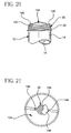
- the mixing blade 52 is preferably configured to include a number of protrusions or "wings" 144 which extend outwardly from the shaft 104 (see FIGS. 21 and 22).
- the wings 144 are aligned with the vanes 116 and are therefore positioned in the vane receiving slots 136 as shown in FIGS. 21 and 22. As such, rotation of the mixing blade 52, and therefore the wings 144, causes similar rotation of the blade wiping diaphragm 134.
- the wings 144 also function to retain the blade wiping diaphragm 134 on the mixing blade 52 prior to securement of the mixing head assembly 30 to the cartridge 16.
- the blade wiping diaphragm 134 is initially secured to the wings 144 of the mixing blade 52 prior to use of the mixing device 10.
- the powder bone cement component may be poured or otherwise advanced into the open end (i.e. the upper end 20) of the cartridge 16. Once the powder component has been poured into the open end of the cartridge 16, the mixing head assembly 30 is screwed onto the threads 22 of the upper end 20 of the cartridge 16.
- the outer peripheral edge 142 of the blade wiping diaphragm 134 is pressed or otherwise advanced under each of the snaps 140 in order to secure the diaphragm 134 to the cartridge 16.
- such positioning of the outer peripheral edge 142 of the blade wiping diaphragm 134 under the snaps 140 allows for retention of the blade wiping diaphragm 134 during subsequent removal of the mixing head assembly 30.
- the configuration of the mixing device 10 in which the blade wiping diaphragm 134 is rotated in concert with the mixing blade 52 reduces the number of vane receiving slots 136 that must be included in the construction of the blade wiping diaphragm 134. Specifically, since the wings 144 are retained in the slots 136, the vanes 116 (which are aligned with the wings 144) are likewise at all times aligned with the vane receiving slots 136. Hence, at any given time, the mixing blade 52 may be removed by pulling the vanes 116 of the blade 52 through the vane receiving slots 136. Such a reduction in the number of vane receiving slots 136 facilitates ease of manufacture of the blade wiping diaphragm 134.
- the shaft 104 of the mixing blade 52 also has an upper shoulder 146 and a lower shoulder 148 defined therein.
- the body of blade wiping diaphragm 134 is captured or otherwise positioned between the upper shoulder 146 and the lower shoulder 148.
- the upper shoulder 146 is greater in diameter than the lower shoulder 148.
- the upper shoulder prevents upward movement of the blade wiping diaphragm 134.
- the lower shoulder 148 is somewhat smaller in diameter and includes a number of rounded edges.
- the lower shoulder 148 supports the blade wiping diaphragm 134 in its desired position, but also allows for removal of the mixing blade 52 since the lower shoulder may be advance through the shaft receiving opening 138 of the blade wiping diaphragm 134 during removal of the blade 52.
- the mixing device 10 of the present invention may be utilized to deliver the mixed bone cement.
- the lower gear housing 38 is unscrewed from the cartridge 16 so that the mixing head assembly 30 may be removed from the cartridge 16. Thereafter, the delivery nozzle assembly 150 may be screwed onto the threads 22 of the upper end 20 of the cartridge 16.
- the nozzle assembly 150 includes a nozzle 152 and an elongated tube 154.
- the length and/or diameter of the elongated tube 154 may be varied in order to fit the requirements of a given delivery application. Moreover, it should also be noted that in certain situations, it may be desirable to dispense (i.e. delivery) the mixed bone cement directly through the nozzle 152 without the use of the elongated tube 154.
- the lower end 24 of the cartridge 18 is unscrewed from the base 34 thereby separating the canister 12 from the base 34.
- Such removal of the base 34 also exposes a bottom surface 156 of the plunger 110 (see FIG. 7).
- the canister 12 may then be placed in the chamber of a delivery gun mechanism (not shown) much in the same way as a tube of caulk is placed in a household caulk gun.
- a contact member urges the plunger 110 in the general direction toward the nozzle assembly 150.
- Such movement of the plunger 110 forces the mixed bone cement within the mixing chamber 14 through the openings defined in the blade wiping diaphragm 134 (i.e. the vane receiving slots 136 and the shaft receiving opening 138) and then through the nozzle 152 and tube 154 of the nozzle assembly.
- the blade wiping diaphragm 134 i.e. the vane receiving slots 136 and the shaft receiving opening 138
- the bone cement mixing device 10 of the present invention is utilized to mix a liquid bone cement component with a powder bone cement component and thereafter deliver the mixed bone cement to a desired location during performance of a surgical procedure.
- the powder bone cement component is first placed in the mixing chamber 14 of the canister 12.
- a quantity of the powder bone cement component is poured or otherwise advanced into the open end of the cartridge 16 (i.e. the upper end 20 of the cartridge 16) and hence into the mixing chamber 14 of the canister 12.
- the canister 12 is preferably configured to accommodate (i.e. hold) at least 120 grams (e.g. three batches of 40 grams each) of powder bone cement.
- the mixing head 30 is screwed onto the upper end 20 of the cartridge 16.
- the threads 28 of the lower gear housing 38 are threadingly advanced onto the threads 22 of the upper end 20 of the cartridge 16 until the mixing head 30 is fully secured to the canister 12.
- the O-ring 158 is compressed thereby sealing the mixing head 30 to the canister 12 (see FIG. 19).
- the blade wiping diaphragm 134 (which is secured to the wings 144 of the mixing blade 52) is secured to the canister 12.
- the outer peripheral edge 142 of the blade wiping diaphragm 134 is pressed or otherwise advanced under the snaps 140 of the cartridge 16 thereby securing the diaphragm 134 to the cartridge 16.
- the liquid bone cement component (e.g. the monomer) may be advanced into the mixing chamber 12 and hence into contact with the powder bone cement component positioned therein.
- the port cap 128 is first removed from sealing engagement with the monomer delivery port 122 in order to permit fluid access to the mixing chamber 14 of the canister 12.
- the required quantity of liquid cement component may be introduced into the mixing chamber 14 of the canister 12 through the delivery port 122.
- an outlet coupling of a monomer delivery device (not shown) is first sealingly coupled to the monomer delivery port 122 of the mixing device 10.
- the liquid cement component e.g.
- the monomer contained in the monomer delivery device is introduced into the mixing chamber 14 via the fluid path which includes the delivery port 122, the tube 124, the fluid passageway 118 of the shaft 104, and the fluid orifices 120 of the shaft 104.
- the monomer is delivered at various locations throughout the depth of the powder component present in the mixing chamber 14.
- the liquid component e.g. the monomer
- the liquid component is delivered at locations throughout the height of the canister 12 thereby allowing the liquid to be interspersed throughout the depth of the powder component present in the mixing chamber 12.
- the monomer delivery port 122 is preferably embodied as a luer lock or other type of sealable component, and therefore "mated” with a similar type of outlet coupling on the monomer delivery device, the monomer is dispensed into the tube 124 (and hence the mixing chamber 14 of the canister 12) while preventing monomer vapours from escaping between the monomer delivery device and the mixing device 10 (e.g. between luer of the monomer delivery device and the luer lock of the mixing device 10).
- a vacuum source (not shown) is fluidly coupled to the vacuum port 132 of the lower gear housing 38 of the mixing head assembly 30 in order to draw air from the mixing chamber 14 of the mixing device 10.
- the introduction of a vacuum is useful during the introduction of the liquid cement component into the mixing chamber 14 since the presence of lower pressure within the chamber 14 tends to draw the liquid (i.e. the monomer) through the fluid orifices 120 of the shaft 104 and into the mixing chamber 14.
- the presence of the vacuum also removes vapours and the like from the mixing device 10 thereby further reducing the occasions in which such vapours escape from the device 10.
- the cap 128 is positioned back in sealing engagement within the delivery port 122 so as to prevent the escape of any vapours associated with the delivered monomer. Thereafter, the operator may commence to mix the liquid cement component and the powder cement component with one another.
- the gear train 46 of the present invention is configured such that the direction of rotation of the output pinion 48 (and hence the mixing blade 52) alternates (i.e. changes) despite rotation of the crank 40 (and hence the directional gear 54) in only a single direction.
- the idler gear 56 is engaged with the outer gear teeth 90 of the directional gear 54
- the output pinion 48 and hence the mixing blade 52 is rotated in a first direction.
- the idler gear disengages the outer gear teeth 90 and engages the inner gear teeth 86 of the directional gear 54
- the direction of travel of the output pinion 48 and hence the mixing blade 52 is reversed thereby creating alternating or reciprocating motion.
- the relatively large number of individual gear teeth associated with the outer gear teeth 90 creates a relatively large gear ratio with the idler gear 56 relative to the gear ratio created by inner gear teeth 86 and the idler gear 56, varying angular distances of travel and speeds of the mixing blade 52 are created.
- the mixing blade 52 is driven across 540° of rotation in a first direction and then reversed and driven across 135° of rotation in the opposite direction.
- the crank 40 when as the operator advances the crank 40 through such an entire revolution (i.e.
- the mixing blade 52 is driven three times as quickly in the first direction as it is when reversed and driven in the opposite direction.
- Such a reciprocating movement of the mixing blade 52 i.e. at varying angular distances and speeds) creates desirable "agitation" within the mixing chamber 14 of the canister 12 which increases the mix quality of the mixing device 10 by reducing, if not eliminating, the amount of the powder component bone cement which is not thoroughly mixed with the liquid component of the bone cement.
- the blade wiping diaphragm 134 is likewise rotated.
- the blade wiping diaphragm 134 is rotatable relative to the cartridge 16.
- the outer peripheral edge 142 of the blade wiping diaphragm 134 is positioned under the snaps 140 in order to secure the diaphragm 134 to the cartridge 16 in a manner which allows the diaphragm to rotate relative to the cartridge 16.
- the wings 144 of the mixing blade 52 are positioned in the vane receiving slots 136 thereby causing the blade wiping diaphragm 134 to be rotated in concert with the mixing blade 52.
- the mixing head assembly 30 is removed from the canister 12.
- the lower gear housing 38 is unscrewed from the cartridge 16 so that the mixing head assembly 30 may be removed from the cartridge 16 thereby allowing the delivery nozzle assembly 150 (see FIGS. 23 and 24) to be screwed onto the cartridge 16 in its place.
- the vanes 116 of the mixing blade 52 are advanced through the vane receiving slots 136 of the blade wiping diaphragm 134.
- the mixing blade 52 may be "pulled through" the openings (i.e. the vane receiving slots 136 and the shaft receiving opening 138) defined in the blade wiping diaphragm 134 without removing the blade wiping device.
- Such advancement of the vanes 116 through the vane receiving slots 136 wipes or otherwise removes any residual bone cement from the vanes 116 thereby preventing such residual bone cement from being wasted (i.e. removed from the mixing chamber 14, but not utilized in the surgical procedure).
- the mixing device 10 of the present invention may be utilized to deliver the mixed bone cement.
- the lower gear housing 38 is unscrewed from the cartridge 16 so that the mixing head assembly 30 may be removed from the cartridge 16.
- the delivery nozzle assembly 150 is screwed onto the threads 22 of the upper end 20 of the cartridge 16.
- the lower end 24 of the cartridge 18 is then unscrewed from the base 34 thereby separating the canister 12 from the base 34.
- such removal of the base 34 also exposes the bottom surface 156 of the plunger 110.
- the canister 12 may then be placed in the chamber of a delivery gun mechanism (not shown) much in the same way as a tube of caulk is placed in a household caulk gun.
- a contact member urges the plunger 110 in the general direction toward the nozzle assembly 150.
- Such movement of the plunger 110 forces the mixed bone cement within the mixing chamber 14 through the openings defined in the blade wiping diaphragm 134 (i.e. the vane receiving slots 136 and the shaft receiving opening 138) and then through the nozzle 152 and tube 154 of the nozzle assembly 150 thereby delivering the mixed bone cement to a desired location.
- bone cement mixing device 10 of the present invention provide numerous advantages over heretofore designed mixing apparatus.
- the alternating or reciprocating action of the mixing blade 52 enhances the quality of the mixed bone cement by reducing, if not eliminating, the amount of powder component which is not adequately mixed with the liquid component.
- such alternating or reciprocating action is advantageously generated by rotation of the crank 40 in only a single direction and at a single speed.
- the configuration of the gear train 46 eliminates the need for the operator to manually reverse the direction of the crank 40 and/or manually alter the speed at which the crank 40 is being rotated in order to produce the desired blade movement.
- the sealed relationship between the outlet coupling of the monomer delivery device and the delivery port 122 of the mixing device 10 provides for delivery and mixing of the bone cement without exposing the operator of the system to monomer vapours.
- the liquid component e.g. the monomer
- the liquid component is delivered at locations throughout the height of the canister 12 thereby allowing the liquid to be interspersed throughout the entire depth of the powder component present in the mixing chamber 12.
- this is a significant advantage over heretofore designed systems in which the monomer is poured or otherwise advanced through the lid of the mixing apparatus thereby only allowing the monomer to be introduced to the "top" of the powder within the mixing apparatus.
- the structure of the present invention also provide advantages over heretofore designed system having a delivery path through the mixing shaft of the system which have an opening only at the bottom end of the shaft (similar to a common drinking straw).
- the monomer only flows out of the bottom of the shaft and in some cases may be restricted by the plunger on which the lower end of the shaft rests.
Landscapes
- Chemical & Material Sciences (AREA)
- Chemical Kinetics & Catalysis (AREA)
- Mixers Of The Rotary Stirring Type (AREA)
- Preparation Of Clay, And Manufacture Of Mixtures Containing Clay Or Cement (AREA)
- Prostheses (AREA)
- Surgical Instruments (AREA)
- Mixers With Rotating Receptacles And Mixers With Vibration Mechanisms (AREA)
Claims (16)
- Eine Knochenzement-Mischvorrichtung (10), welche umfasst:einen Griff (42);ein Eingabegetriebe (54), welches zur Drehung um eine Mittelachse als Reaktion auf das Drehen des Griffs (42) gebracht wird, wobei (i) das Eingabegetriebe (54) einen ersten Eingabe-Getriebezähnesatz (86) und einen zweiten Eingabe-Getriebezähnesatz (90) einschließt, (ii) der erste Eingabe-Getriebezähnesatz (86) in einem ersten radialen Abstand von der Mittelachse beabstandet ist, (iii) der zweite Eingabe-Getriebezähnesatz (90) in einem zweiten radialen Abstand von der Mittelachse beabstandet ist, (iv) der zweite radiale Abstand größer als der erste radiale Abstand ist, (v) der erste Eingabe-Getriebezähnesatz (86) sich nach außen weg von der Mittelachse erstreckt und (vi) der zweite Eingabe-Getriebezähnesatz (90) sich nach innen zur Mittelachse hin erstreckt;ein Zwischengetriebe (56), wobei das Eingabegetriebe (54) so gestaltet ist, dass während dessen Drehung (i) der erste Eingabe-Getriebezähnesatz (86) das Zwischengetriebe (56) während eines ersten Zeitraums in Zahneingriff nimmt und (ii) der zweite Eingabe-Getriebezähnesatz (90) das Zwischengetriebe (56) während eines zweiten Zeitraums in Zahneingriff nimmt, der sich vom ersten Zeitraum unterscheidet;ein Ausgabegetriebe (48), welches zur Drehung als Reaktion auf das Drehen des Zwischengetriebes (56) veranlasst wird; undeine Mischschaufel (52), welche zur Drehung als Reaktion auf das Drehen des Ausgabegetriebes (48) veranlasst wird.
- Vorrichtung, wie gemäß Anspruch 1 beansprucht, welche einen ersten Getriebegehäuse-Abschnitt (36) umfasst; und einen zweiten Getriebegehäuse-Abschnitt (38), in dem (a) eine Getriebekammer definiert ist, wenn der erste Getriebegehäuse-Abschnitt (36) am zweiten Getriebegehäuse-Abschnitt (38) befestigt ist, (b) das Eingabegetriebe (54), das Zwischengetriebe (56) und das Ausgabegetriebe (48) innerhalb der Getriebekammer positioniert sind, und (c) der Griff (42) und die Mischschaufel (52) außerhalb der Getriebekammer positioniert sind.
- Vorrichtung, wie gemäß Anspruch 1 beansprucht, wobei die Mittelachse auf einer Ebene liegt, welche das Eingabegetriebe (54) in eine erste Eingabegetriebeseite und in eine zweite Eingabegetriebeseite teilt, und das Eingabegetriebe (54) so gestaltet ist, dass (i) der erste Eingabe-Getriebezähnesatz (86) vollständig auf der ersten Eingabegetriebeseite positioniert ist, und dass (ii) der zweite Eingabe-Getriebezähnesatz (90) vollständig auf der zweiten Eingabegetriebeseite positioniert ist.
- Vorrichtung, wie in Anspruch 1 beansprucht, wobei die Mischschaufel (52) eine Welle (104) und eine Reihe Flügel (116) umfasst, die sich von der Welle (104) nach außen erstrecken, wobei die Welle (104) mit der Mittelachse ausgefluchtet ist.
- Vorrichtung, wie in Anspruch 1 beansprucht, wobei das Zwischengetriebe (56) sich um eine versetzte Achse dreht, die von der Mittelachse beabstandet ist.
- Vorrichtung, wie in Anspruch 2 beansprucht, wobei das Zwischengetriebe (56) sich um eine versetzte Achse dreht, die von der Mittelachse beabstandet ist, der zweite Getriebegehäuseabschnitt (38) einen Ständer (66) umfasst, der mit der versetzten Achse ausgefluchtet ist, und wobei das Zwischengetriebe (56) eine Öffnung (64) umfasst, die den Ständer (66) so aufnimmt, dass das Zwischengetriebe (56) drehbar an den zweiten Getriebegehäuseabschnitt (38) angekoppelt ist.
- Vorrichtung, wie in Anspruch 1 beansprucht, wobei das Zwischengetriebe (56) das Ausgabegetriebe (48) in Zahneingriff nimmt.
- Vorrichtung, wie in Anspruch 1 beansprucht, wobei das Ausgabegetriebe (48) zur Drehung um die Mittelachse als Reaktion auf das Drehen des Zwischengetriebes (56) veranlasst wird.
- Vorrichtung, wie in Anspruch 1 beansprucht, wobei das Eingabegetriebe (54) nichtdrehbar am Griff (42) befestigt ist.
- Vorrichtung, wie in Anspruch 1 beansprucht, wobei das Eingabegetriebe (54) eine ringförmige, darin definierte Vertiefung (70) aufweist, wobei das Zwischengetriebe einen Ständer (68) umfasst, der innerhalb der ringförmigen Vertiefung (70) aufgenommen wird und wobei sich der Ständer (68) während der Drehung des Eingabegetriebes (54) in der Vertiefung (70) befindet.
- Vorrichtung, wie in Anspruch 1 beansprucht, wobei das Zwischengetriebe (56) in einer ersten Drehrichtung während des ersten Zeitraums angetrieben wird, das Zwischengetriebe (56) in einer zweiten Drehrichtung während des zweiten Zeitraums angetrieben wird und die erste Drehrichtung der zweiten Drehrichtung entgegengesetzt ist..
- Vorrichtung, wie in Anspruch 11 beansprucht, wobei das Eingabegetriebe (54) sich in der zweiten Drehrichtung sowohl während des ersten Zeitraums als auch während des zweiten Zeitraums bewegt.
- Vorrichtung, wie in Anspruch 1 beansprucht, wobei das Zwischengetriebe (56) so angetrieben wird, dass es sich während des ersten Zeitraums mit einer ersten Winkelgeschwindigkeit dreht, das Zwischengetriebe (56) so angetrieben wird, dass es sich während des ersten Zeitraums mit einer zweiten Winkelgeschwindigkeit dreht und die erste Winkelgeschwindigkeit geringer ist als die zweite Winkelgeschwindigkeit.
- Vorrichtung, wie in Anspruch 1 beansprucht, wobei das Zwischengetriebe (56) so angetrieben wird, dass es sich mit einer ersten Ausgabe-Winkelgeschwindigkeit als Reaktion darauf dreht, dass das Eingabegetriebe (54) mit einer Eingabe-Winkelgeschwindigkeit gedreht wird, wobei das Zwischengetriebe (56) so angetrieben wird, dass es sich mit einer zweiten Ausgabe-Winkelgeschwindigkeit als Reaktion darauf dreht, dass das Eingabegetriebe (54) mit der Eingabe-Winkelgeschwindigkeit gedreht wird und die erste Winkelgeschwindigkeit geringer ist als die zweite Winkelgeschwindigkeit.
- Vorrichtung, wie in Anspruch 1 beansprucht, wobei als Reaktion darauf, dass das Eingabegetriebe (54) um eine Umdrehung in einer Drehrichtung im Uhrzeigersinn gedreht wird, das Zwischengetriebe (56) (i) um einen ersten Drehabstand in einer Drehrichtung entgegen dem Uhrzeigersinn angetrieben wird, und (ii) um einen zweiten Drehabstand in einer Drehrichtung im Uhrzeigersinn, und wobei der erste Drehabstand geringer ist als der zweite Drehabstand.
- Vorrichtung, wie in Anspruch 15 beansprucht, wobei das Zwischengetriebe (56) das Ausgabegetriebe (48) in Zahneingriff nimmt, und das Ausgabegetriebe (48) nichtdrehbar mit der Mischschaufel (52) verbunden ist.
Applications Claiming Priority (4)
| Application Number | Priority Date | Filing Date | Title |
|---|---|---|---|
| US25080800P | 2000-12-01 | 2000-12-01 | |
| US250808P | 2000-12-01 | ||
| US2045 | 2001-11-15 | ||
| US10/002,045 US6702455B2 (en) | 2000-12-01 | 2001-11-15 | Bone cement mixing apparatus having improved gearing arrangement for driving a mixing blade |
Publications (3)
| Publication Number | Publication Date |
|---|---|
| EP1210975A2 EP1210975A2 (de) | 2002-06-05 |
| EP1210975A3 EP1210975A3 (de) | 2003-04-09 |
| EP1210975B1 true EP1210975B1 (de) | 2005-06-22 |
Family
ID=26669840
Family Applications (1)
| Application Number | Title | Priority Date | Filing Date |
|---|---|---|---|
| EP01310078A Expired - Lifetime EP1210975B1 (de) | 2000-12-01 | 2001-11-30 | Knochenzementmischvorrichtung mit Getriebeanordnung zum Antrieb einer Mischschaufel |
Country Status (6)
| Country | Link |
|---|---|
| US (1) | US6702455B2 (de) |
| EP (1) | EP1210975B1 (de) |
| JP (1) | JP2002272757A (de) |
| AT (1) | ATE298264T1 (de) |
| AU (1) | AU783862B2 (de) |
| DE (1) | DE60111605T2 (de) |
Cited By (1)
| Publication number | Priority date | Publication date | Assignee | Title |
|---|---|---|---|---|
| DE102014106873B4 (de) * | 2014-05-15 | 2016-12-08 | Heraeus Medical Gmbh | Vorrichtung und Verfahren zum Mischen eines Mehrkomponentenzements |
Families Citing this family (24)
| Publication number | Priority date | Publication date | Assignee | Title |
|---|---|---|---|---|
| US6921192B2 (en) * | 2002-03-29 | 2005-07-26 | Depuy Orthopaedics, Inc. | Bone cement mixing apparatus |
| EP2311408B1 (de) * | 2003-03-14 | 2019-02-20 | DePuy Spine, Inc. | Hydraulische Vorrichtung zur Knochenzementeinspritzung bei perkutaner Vertebroplastie |
| US8066713B2 (en) | 2003-03-31 | 2011-11-29 | Depuy Spine, Inc. | Remotely-activated vertebroplasty injection device |
| US8415407B2 (en) | 2004-03-21 | 2013-04-09 | Depuy Spine, Inc. | Methods, materials, and apparatus for treating bone and other tissue |
| WO2005030034A2 (en) | 2003-09-26 | 2005-04-07 | Depuy Spine, Inc. | Device for delivering viscous material |
| US7524103B2 (en) * | 2003-11-18 | 2009-04-28 | Boston Scientific Scimed, Inc. | Apparatus for mixing and dispensing a multi-component bone cement |
| CA2575699C (en) | 2004-07-30 | 2014-07-08 | Disc-O-Tech Medical Technologies Ltd. | Methods, materials and apparatus for treating bone and other tissue |
| US20080319445A9 (en) * | 2004-08-17 | 2008-12-25 | Scimed Life Systems, Inc. | Apparatus and methods for delivering compounds into vertebrae for vertebroplasty |
| US8038682B2 (en) * | 2004-08-17 | 2011-10-18 | Boston Scientific Scimed, Inc. | Apparatus and methods for delivering compounds into vertebrae for vertebroplasty |
| CN101166487A (zh) * | 2005-04-29 | 2008-04-23 | 惠氏公司 | 药物输送装置以及相关的部件、系统和方法 |
| US9381024B2 (en) | 2005-07-31 | 2016-07-05 | DePuy Synthes Products, Inc. | Marked tools |
| US9918767B2 (en) | 2005-08-01 | 2018-03-20 | DePuy Synthes Products, Inc. | Temperature control system |
| US8360629B2 (en) * | 2005-11-22 | 2013-01-29 | Depuy Spine, Inc. | Mixing apparatus having central and planetary mixing elements |
| BRPI0716546A2 (pt) * | 2006-09-07 | 2013-09-24 | Wyeth Corp | sistemas de mistura de cimento àsseo e mÉtodos relacionados |
| US9642932B2 (en) | 2006-09-14 | 2017-05-09 | DePuy Synthes Products, Inc. | Bone cement and methods of use thereof |
| EP3095511A1 (de) | 2006-10-19 | 2016-11-23 | Depuy Spine Inc. | Versiegelter behälter |
| US8136978B2 (en) * | 2009-05-27 | 2012-03-20 | Pacific Market International, Llc | Tumbler with stirring assembly |
| CN102350248A (zh) * | 2011-07-22 | 2012-02-15 | 上海弗鲁克科技发展有限公司 | 固液分散混合设备 |
| US9649782B1 (en) * | 2013-03-11 | 2017-05-16 | Galomb, Inc. | Injection tube assembly with integrated material stripping element and a polymer mixing system comprising the same |
| US9615816B2 (en) | 2013-03-15 | 2017-04-11 | Vidacare LLC | Drivers and drive systems |
| US10556209B2 (en) * | 2016-03-27 | 2020-02-11 | Ashish Gandhi | Protein blender cup |
| US11344855B2 (en) * | 2019-07-09 | 2022-05-31 | Vivex Biologics Group, Inc. | Mixing container and method of use |
| CN111389257B (zh) * | 2020-04-07 | 2022-07-12 | 史敏敏 | 一种农业生产用培育土制备装置 |
| CN115920693B (zh) * | 2022-12-15 | 2023-11-28 | 常州市宏寰机械有限公司 | 一种多轴调质器 |
Family Cites Families (25)
| Publication number | Priority date | Publication date | Assignee | Title |
|---|---|---|---|---|
| US341306A (en) * | 1886-05-04 | Daniel j | ||
| US409533A (en) * | 1889-08-20 | Churn | ||
| US347916A (en) * | 1886-08-24 | Isaac bogaet | ||
| US215850A (en) * | 1879-05-27 | Improvement in churns | ||
| US642650A (en) * | 1899-06-15 | 1900-02-06 | George W Walker | Churn. |
| FR711436A (fr) | 1930-05-19 | 1931-09-09 | Dispositif de transmission de mouvement avec inversion périodique automatique du sens de rotation | |
| US2696022A (en) * | 1951-04-23 | 1954-12-07 | Steinbock | Investment mixer |
| US4185072A (en) * | 1977-02-17 | 1980-01-22 | Diemolding Corporation | Orthopedic cement mixer |
| US4638676A (en) * | 1985-02-25 | 1987-01-27 | Rota-Flex Corporation | Reciprocating drive mechanism with positive pinion-to-rack gear engagement |
| US4961647A (en) * | 1986-04-04 | 1990-10-09 | Dhd Medical Products | Orthopedic cement mixer |
| US5265956A (en) * | 1991-09-30 | 1993-11-30 | Stryker Corporation | Bone cement mixing and loading apparatus |
| GB9126011D0 (en) * | 1991-12-06 | 1992-02-05 | Summit Medical Ltd | Bone cement mixing device |
| CA2166789A1 (en) * | 1993-07-06 | 1995-01-19 | Michael L. Earle | Automated bone cement mixing apparatus |
| US5368386A (en) * | 1993-11-16 | 1994-11-29 | Murray; William M. | Manual bone cement mixing device |
| GB9403362D0 (en) * | 1994-02-22 | 1994-04-13 | Summit Medical Ltd | Bone cement mixing apparatus |
| DE4425218A1 (de) * | 1994-07-16 | 1996-01-18 | Merck Patent Gmbh | Vorrichtung zum Mischen und Austragen von Knochenzement |
| US5549381A (en) * | 1995-05-19 | 1996-08-27 | Hays; Greta J. | Method and apparatus for mixing polymeric bone cement components |
| US5797678A (en) * | 1995-09-25 | 1998-08-25 | Murray; William M. | Bone cement mixing device and method |
| US5797679A (en) * | 1996-02-09 | 1998-08-25 | Stryker Corporation | Surgical cement mixer apparatus |
| US6033105A (en) * | 1996-11-15 | 2000-03-07 | Barker; Donald | Integrated bone cement mixing and dispensing system |
| US5842786A (en) * | 1997-03-07 | 1998-12-01 | Solomon; Alan | Method and device for mixing medical compositions |
| US6042262A (en) * | 1997-07-29 | 2000-03-28 | Stryker Technologies Corportion | Apparatus for storing, mixing, and dispensing two-component bone cement |
| US5924324A (en) * | 1997-10-09 | 1999-07-20 | Ut Automotive Dearborn, Inc. | Movable gear drive windshield wiper |
| US6024480A (en) * | 1998-02-09 | 2000-02-15 | Immedica | Vial package for a bone cement mixer and dispenser |
| US6116773A (en) * | 1999-01-22 | 2000-09-12 | Murray; William M. | Bone cement mixer and method |
-
2001
- 2001-11-15 US US10/002,045 patent/US6702455B2/en not_active Expired - Lifetime
- 2001-11-30 AU AU95223/01A patent/AU783862B2/en not_active Ceased
- 2001-11-30 DE DE60111605T patent/DE60111605T2/de not_active Expired - Lifetime
- 2001-11-30 AT AT01310078T patent/ATE298264T1/de not_active IP Right Cessation
- 2001-11-30 EP EP01310078A patent/EP1210975B1/de not_active Expired - Lifetime
- 2001-12-03 JP JP2001369126A patent/JP2002272757A/ja active Pending
Cited By (1)
| Publication number | Priority date | Publication date | Assignee | Title |
|---|---|---|---|---|
| DE102014106873B4 (de) * | 2014-05-15 | 2016-12-08 | Heraeus Medical Gmbh | Vorrichtung und Verfahren zum Mischen eines Mehrkomponentenzements |
Also Published As
| Publication number | Publication date |
|---|---|
| EP1210975A2 (de) | 2002-06-05 |
| US6702455B2 (en) | 2004-03-09 |
| ATE298264T1 (de) | 2005-07-15 |
| AU783862B2 (en) | 2005-12-15 |
| US20020067657A1 (en) | 2002-06-06 |
| DE60111605T2 (de) | 2006-05-11 |
| JP2002272757A (ja) | 2002-09-24 |
| AU9522301A (en) | 2002-06-06 |
| EP1210975A3 (de) | 2003-04-09 |
| DE60111605D1 (de) | 2005-07-28 |
Similar Documents
| Publication | Publication Date | Title |
|---|---|---|
| EP1210975B1 (de) | Knochenzementmischvorrichtung mit Getriebeanordnung zum Antrieb einer Mischschaufel | |
| EP1210974B1 (de) | Knochenzementmischvorrichtung mit besonderer Mischschaufelanordnung | |
| US5494349A (en) | Bone cement mixing device | |
| US6033105A (en) | Integrated bone cement mixing and dispensing system | |
| US6176607B1 (en) | Apparatus for dispensing a liquid component of a two-component bone cement and for storing, mixing, and dispensing the cement | |
| EP0938368B1 (de) | Integriertes knochenzementmisch- und - spendersystem | |
| EP1068893B1 (de) | Knochenzementmischer | |
| EP1348479B1 (de) | Knochenzementmischvorrichtung | |
| EP1257237B8 (de) | Mischvorrichtung für orthopädischen zement | |
| AU2001230218A1 (en) | Orthopaedic cement mixing device | |
| AU2004210409B2 (en) | Orthopaedic cement mixing device | |
| GB2430165A (en) | Othopaedic cement mixing device |
Legal Events
| Date | Code | Title | Description |
|---|---|---|---|
| PUAI | Public reference made under article 153(3) epc to a published international application that has entered the european phase |
Free format text: ORIGINAL CODE: 0009012 |
|
| AK | Designated contracting states |
Kind code of ref document: A2 Designated state(s): AT BE CH CY DE DK ES FI FR GB GR IE IT LI LU MC NL PT SE TR |
|
| AX | Request for extension of the european patent |
Free format text: AL;LT;LV;MK;RO;SI |
|
| PUAL | Search report despatched |
Free format text: ORIGINAL CODE: 0009013 |
|
| AK | Designated contracting states |
Kind code of ref document: A3 Designated state(s): AT BE CH CY DE DK ES FI FR GB GR IE IT LI LU MC NL PT SE TR Designated state(s): AT BE CH CY DE DK ES FI FR GB GR IE IT LI LU MC NL PT SE TR |
|
| AX | Request for extension of the european patent |
Extension state: AL LT LV MK RO SI |
|
| RIC1 | Information provided on ipc code assigned before grant |
Ipc: 7B 01F 7/16 B Ipc: 7A 61F 2/46 B Ipc: 7F 16H 19/08 B Ipc: 7B 01F 15/00 B Ipc: 7B 01F 13/00 A |
|
| 17P | Request for examination filed |
Effective date: 20030925 |
|
| 17Q | First examination report despatched |
Effective date: 20031022 |
|
| AKX | Designation fees paid |
Designated state(s): AT BE CH CY DE DK ES FI FR GB GR IE IT LI LU MC NL PT SE TR |
|
| GRAP | Despatch of communication of intention to grant a patent |
Free format text: ORIGINAL CODE: EPIDOSNIGR1 |
|
| RIN1 | Information on inventor provided before grant (corrected) |
Inventor name: SACKETT, SAM Inventor name: DECESARE, PAUL Inventor name: LONG, JACK F. Inventor name: GUTELIUS, PATRICK Inventor name: BATTLES, CHRISTOPHER Inventor name: VENDRELY, TIMOTHY G. |
|
| GRAS | Grant fee paid |
Free format text: ORIGINAL CODE: EPIDOSNIGR3 |
|
| GRAA | (expected) grant |
Free format text: ORIGINAL CODE: 0009210 |
|
| AK | Designated contracting states |
Kind code of ref document: B1 Designated state(s): AT BE CH CY DE DK ES FI FR GB GR IE IT LI LU MC NL PT SE TR |
|
| PG25 | Lapsed in a contracting state [announced via postgrant information from national office to epo] |
Ref country code: AT Free format text: LAPSE BECAUSE OF FAILURE TO SUBMIT A TRANSLATION OF THE DESCRIPTION OR TO PAY THE FEE WITHIN THE PRESCRIBED TIME-LIMIT Effective date: 20050622 Ref country code: FI Free format text: LAPSE BECAUSE OF FAILURE TO SUBMIT A TRANSLATION OF THE DESCRIPTION OR TO PAY THE FEE WITHIN THE PRESCRIBED TIME-LIMIT Effective date: 20050622 Ref country code: NL Free format text: LAPSE BECAUSE OF FAILURE TO SUBMIT A TRANSLATION OF THE DESCRIPTION OR TO PAY THE FEE WITHIN THE PRESCRIBED TIME-LIMIT Effective date: 20050622 Ref country code: TR Free format text: LAPSE BECAUSE OF FAILURE TO SUBMIT A TRANSLATION OF THE DESCRIPTION OR TO PAY THE FEE WITHIN THE PRESCRIBED TIME-LIMIT Effective date: 20050622 Ref country code: BE Free format text: LAPSE BECAUSE OF FAILURE TO SUBMIT A TRANSLATION OF THE DESCRIPTION OR TO PAY THE FEE WITHIN THE PRESCRIBED TIME-LIMIT Effective date: 20050622 |
|
| REG | Reference to a national code |
Ref country code: GB Ref legal event code: FG4D |
|
| RIN1 | Information on inventor provided before grant (corrected) |
Inventor name: BATTLES, CHRISTOPHER Inventor name: LONG, JACK F. Inventor name: SACKETT, SAM Inventor name: GUTELIUS, PATRICK Inventor name: VENDRELY, TIMOTHY G. Inventor name: DECESARE, PAUL |
|
| REG | Reference to a national code |
Ref country code: CH Ref legal event code: EP |
|
| REG | Reference to a national code |
Ref country code: IE Ref legal event code: FG4D |
|
| REF | Corresponds to: |
Ref document number: 60111605 Country of ref document: DE Date of ref document: 20050728 Kind code of ref document: P |
|
| REG | Reference to a national code |
Ref country code: CH Ref legal event code: NV Representative=s name: E. BLUM & CO. PATENTANWAELTE |
|
| PG25 | Lapsed in a contracting state [announced via postgrant information from national office to epo] |
Ref country code: SE Free format text: LAPSE BECAUSE OF FAILURE TO SUBMIT A TRANSLATION OF THE DESCRIPTION OR TO PAY THE FEE WITHIN THE PRESCRIBED TIME-LIMIT Effective date: 20050922 Ref country code: DK Free format text: LAPSE BECAUSE OF FAILURE TO SUBMIT A TRANSLATION OF THE DESCRIPTION OR TO PAY THE FEE WITHIN THE PRESCRIBED TIME-LIMIT Effective date: 20050922 Ref country code: GR Free format text: LAPSE BECAUSE OF FAILURE TO SUBMIT A TRANSLATION OF THE DESCRIPTION OR TO PAY THE FEE WITHIN THE PRESCRIBED TIME-LIMIT Effective date: 20050922 |
|
| PG25 | Lapsed in a contracting state [announced via postgrant information from national office to epo] |
Ref country code: ES Free format text: LAPSE BECAUSE OF FAILURE TO SUBMIT A TRANSLATION OF THE DESCRIPTION OR TO PAY THE FEE WITHIN THE PRESCRIBED TIME-LIMIT Effective date: 20051003 |
|
| PGFP | Annual fee paid to national office [announced via postgrant information from national office to epo] |
Ref country code: MC Payment date: 20051026 Year of fee payment: 5 |
|
| PG25 | Lapsed in a contracting state [announced via postgrant information from national office to epo] |
Ref country code: PT Free format text: LAPSE BECAUSE OF FAILURE TO SUBMIT A TRANSLATION OF THE DESCRIPTION OR TO PAY THE FEE WITHIN THE PRESCRIBED TIME-LIMIT Effective date: 20051129 |
|
| PG25 | Lapsed in a contracting state [announced via postgrant information from national office to epo] |
Ref country code: CY Free format text: LAPSE BECAUSE OF FAILURE TO SUBMIT A TRANSLATION OF THE DESCRIPTION OR TO PAY THE FEE WITHIN THE PRESCRIBED TIME-LIMIT Effective date: 20051130 |
|
| NLV1 | Nl: lapsed or annulled due to failure to fulfill the requirements of art. 29p and 29m of the patents act | ||
| PGFP | Annual fee paid to national office [announced via postgrant information from national office to epo] |
Ref country code: LU Payment date: 20051213 Year of fee payment: 5 |
|
| ET | Fr: translation filed | ||
| PLBE | No opposition filed within time limit |
Free format text: ORIGINAL CODE: 0009261 |
|
| STAA | Information on the status of an ep patent application or granted ep patent |
Free format text: STATUS: NO OPPOSITION FILED WITHIN TIME LIMIT |
|
| 26N | No opposition filed |
Effective date: 20060323 |
|
| PG25 | Lapsed in a contracting state [announced via postgrant information from national office to epo] |
Ref country code: MC Free format text: LAPSE BECAUSE OF NON-PAYMENT OF DUE FEES Effective date: 20061130 |
|
| REG | Reference to a national code |
Ref country code: CH Ref legal event code: PFA Owner name: DEPUY ORTHOPAEDICS, INC. Free format text: DEPUY ORTHOPAEDICS, INC.#700 ORTHOPAEDIC DRIVE#WARSAW, INDIANA 46581 (US) -TRANSFER TO- DEPUY ORTHOPAEDICS, INC.#700 ORTHOPAEDIC DRIVE#WARSAW, INDIANA 46581 (US) |
|
| PG25 | Lapsed in a contracting state [announced via postgrant information from national office to epo] |
Ref country code: LU Free format text: LAPSE BECAUSE OF NON-PAYMENT OF DUE FEES Effective date: 20061130 |
|
| REG | Reference to a national code |
Ref country code: FR Ref legal event code: PLFP Year of fee payment: 16 |
|
| REG | Reference to a national code |
Ref country code: FR Ref legal event code: PLFP Year of fee payment: 17 |
|
| REG | Reference to a national code |
Ref country code: FR Ref legal event code: PLFP Year of fee payment: 18 |
|
| PGFP | Annual fee paid to national office [announced via postgrant information from national office to epo] |
Ref country code: DE Payment date: 20191119 Year of fee payment: 19 Ref country code: IE Payment date: 20191111 Year of fee payment: 19 |
|
| PGFP | Annual fee paid to national office [announced via postgrant information from national office to epo] |
Ref country code: IT Payment date: 20191108 Year of fee payment: 19 Ref country code: FR Payment date: 20191014 Year of fee payment: 19 |
|
| PGFP | Annual fee paid to national office [announced via postgrant information from national office to epo] |
Ref country code: CH Payment date: 20191116 Year of fee payment: 19 |
|
| PGFP | Annual fee paid to national office [announced via postgrant information from national office to epo] |
Ref country code: GB Payment date: 20191129 Year of fee payment: 19 |
|
| REG | Reference to a national code |
Ref country code: DE Ref legal event code: R119 Ref document number: 60111605 Country of ref document: DE |
|
| REG | Reference to a national code |
Ref country code: CH Ref legal event code: PL |
|
| GBPC | Gb: european patent ceased through non-payment of renewal fee |
Effective date: 20201130 |
|
| PG25 | Lapsed in a contracting state [announced via postgrant information from national office to epo] |
Ref country code: CH Free format text: LAPSE BECAUSE OF NON-PAYMENT OF DUE FEES Effective date: 20201130 Ref country code: LI Free format text: LAPSE BECAUSE OF NON-PAYMENT OF DUE FEES Effective date: 20201130 |
|
| REG | Reference to a national code |
Ref country code: IE Ref legal event code: MM4A |
|
| PG25 | Lapsed in a contracting state [announced via postgrant information from national office to epo] |
Ref country code: IE Free format text: LAPSE BECAUSE OF NON-PAYMENT OF DUE FEES Effective date: 20201130 Ref country code: IT Free format text: LAPSE BECAUSE OF NON-PAYMENT OF DUE FEES Effective date: 20201130 Ref country code: FR Free format text: LAPSE BECAUSE OF NON-PAYMENT OF DUE FEES Effective date: 20201130 |
|
| PG25 | Lapsed in a contracting state [announced via postgrant information from national office to epo] |
Ref country code: DE Free format text: LAPSE BECAUSE OF NON-PAYMENT OF DUE FEES Effective date: 20210601 Ref country code: GB Free format text: LAPSE BECAUSE OF NON-PAYMENT OF DUE FEES Effective date: 20201130 |