EP1209679A2 - Recording apparatus and method for optical recording medium - Google Patents
Recording apparatus and method for optical recording medium Download PDFInfo
- Publication number
- EP1209679A2 EP1209679A2 EP01126617A EP01126617A EP1209679A2 EP 1209679 A2 EP1209679 A2 EP 1209679A2 EP 01126617 A EP01126617 A EP 01126617A EP 01126617 A EP01126617 A EP 01126617A EP 1209679 A2 EP1209679 A2 EP 1209679A2
- Authority
- EP
- European Patent Office
- Prior art keywords
- recording
- signal
- control data
- area
- pit
- Prior art date
- Legal status (The legal status is an assumption and is not a legal conclusion. Google has not performed a legal analysis and makes no representation as to the accuracy of the status listed.)
- Withdrawn
Links
- 238000000034 method Methods 0.000 title claims abstract description 37
- 230000003287 optical effect Effects 0.000 title claims abstract description 28
- 230000004044 response Effects 0.000 claims description 4
- 230000008569 process Effects 0.000 description 8
- 230000007274 generation of a signal involved in cell-cell signaling Effects 0.000 description 5
- 230000004048 modification Effects 0.000 description 4
- 238000012986 modification Methods 0.000 description 4
- 230000004075 alteration Effects 0.000 description 2
- 238000010586 diagram Methods 0.000 description 2
- 230000008859 change Effects 0.000 description 1
- 238000004590 computer program Methods 0.000 description 1
- 238000012937 correction Methods 0.000 description 1
- 230000006866 deterioration Effects 0.000 description 1
- 238000011161 development Methods 0.000 description 1
- 238000004049 embossing Methods 0.000 description 1
- 230000006872 improvement Effects 0.000 description 1
- 230000010287 polarization Effects 0.000 description 1
- 230000002265 prevention Effects 0.000 description 1
- 238000012545 processing Methods 0.000 description 1
Images





Classifications
-
- G—PHYSICS
- G11—INFORMATION STORAGE
- G11B—INFORMATION STORAGE BASED ON RELATIVE MOVEMENT BETWEEN RECORD CARRIER AND TRANSDUCER
- G11B27/00—Editing; Indexing; Addressing; Timing or synchronising; Monitoring; Measuring tape travel
- G11B27/10—Indexing; Addressing; Timing or synchronising; Measuring tape travel
- G11B27/19—Indexing; Addressing; Timing or synchronising; Measuring tape travel by using information detectable on the record carrier
- G11B27/28—Indexing; Addressing; Timing or synchronising; Measuring tape travel by using information detectable on the record carrier by using information signals recorded by the same method as the main recording
- G11B27/30—Indexing; Addressing; Timing or synchronising; Measuring tape travel by using information detectable on the record carrier by using information signals recorded by the same method as the main recording on the same track as the main recording
- G11B27/3027—Indexing; Addressing; Timing or synchronising; Measuring tape travel by using information detectable on the record carrier by using information signals recorded by the same method as the main recording on the same track as the main recording used signal is digitally coded
-
- G—PHYSICS
- G11—INFORMATION STORAGE
- G11B—INFORMATION STORAGE BASED ON RELATIVE MOVEMENT BETWEEN RECORD CARRIER AND TRANSDUCER
- G11B20/00—Signal processing not specific to the method of recording or reproducing; Circuits therefor
- G11B20/10—Digital recording or reproducing
- G11B20/12—Formatting, e.g. arrangement of data block or words on the record carriers
- G11B20/1217—Formatting, e.g. arrangement of data block or words on the record carriers on discs
-
- G—PHYSICS
- G11—INFORMATION STORAGE
- G11B—INFORMATION STORAGE BASED ON RELATIVE MOVEMENT BETWEEN RECORD CARRIER AND TRANSDUCER
- G11B20/00—Signal processing not specific to the method of recording or reproducing; Circuits therefor
- G11B20/10—Digital recording or reproducing
- G11B20/14—Digital recording or reproducing using self-clocking codes
- G11B20/1403—Digital recording or reproducing using self-clocking codes characterised by the use of two levels
-
- G—PHYSICS
- G11—INFORMATION STORAGE
- G11B—INFORMATION STORAGE BASED ON RELATIVE MOVEMENT BETWEEN RECORD CARRIER AND TRANSDUCER
- G11B27/00—Editing; Indexing; Addressing; Timing or synchronising; Monitoring; Measuring tape travel
- G11B27/10—Indexing; Addressing; Timing or synchronising; Measuring tape travel
- G11B27/19—Indexing; Addressing; Timing or synchronising; Measuring tape travel by using information detectable on the record carrier
- G11B27/24—Indexing; Addressing; Timing or synchronising; Measuring tape travel by using information detectable on the record carrier by sensing features on the record carrier other than the transducing track ; sensing signals or marks recorded by another method than the main recording
-
- G—PHYSICS
- G11—INFORMATION STORAGE
- G11B—INFORMATION STORAGE BASED ON RELATIVE MOVEMENT BETWEEN RECORD CARRIER AND TRANSDUCER
- G11B20/00—Signal processing not specific to the method of recording or reproducing; Circuits therefor
- G11B20/10—Digital recording or reproducing
- G11B20/18—Error detection or correction; Testing, e.g. of drop-outs
-
- G—PHYSICS
- G11—INFORMATION STORAGE
- G11B—INFORMATION STORAGE BASED ON RELATIVE MOVEMENT BETWEEN RECORD CARRIER AND TRANSDUCER
- G11B2220/00—Record carriers by type
- G11B2220/20—Disc-shaped record carriers
- G11B2220/21—Disc-shaped record carriers characterised in that the disc is of read-only, rewritable, or recordable type
- G11B2220/215—Recordable discs
- G11B2220/216—Rewritable discs
-
- G—PHYSICS
- G11—INFORMATION STORAGE
- G11B—INFORMATION STORAGE BASED ON RELATIVE MOVEMENT BETWEEN RECORD CARRIER AND TRANSDUCER
- G11B2220/00—Record carriers by type
- G11B2220/20—Disc-shaped record carriers
- G11B2220/21—Disc-shaped record carriers characterised in that the disc is of read-only, rewritable, or recordable type
- G11B2220/215—Recordable discs
- G11B2220/218—Write-once discs
-
- G—PHYSICS
- G11—INFORMATION STORAGE
- G11B—INFORMATION STORAGE BASED ON RELATIVE MOVEMENT BETWEEN RECORD CARRIER AND TRANSDUCER
- G11B2220/00—Record carriers by type
- G11B2220/20—Disc-shaped record carriers
- G11B2220/25—Disc-shaped record carriers characterised in that the disc is based on a specific recording technology
- G11B2220/2537—Optical discs
- G11B2220/2562—DVDs [digital versatile discs]; Digital video discs; MMCDs; HDCDs
-
- G—PHYSICS
- G11—INFORMATION STORAGE
- G11B—INFORMATION STORAGE BASED ON RELATIVE MOVEMENT BETWEEN RECORD CARRIER AND TRANSDUCER
- G11B7/00—Recording or reproducing by optical means, e.g. recording using a thermal beam of optical radiation by modifying optical properties or the physical structure, reproducing using an optical beam at lower power by sensing optical properties; Record carriers therefor
- G11B7/004—Recording, reproducing or erasing methods; Read, write or erase circuits therefor
- G11B7/0045—Recording
Definitions
- the present invention relates to an apparatus and method for recording on an optical recording medium.
- an optical recording medium having a recording capacity of several gigabytes is in practical use or under development such as a DVD-R (Digital Versatile Disc-Recordable) or a rewritable DVD-RW (DVD-Rewritable).
- DVD-R Digital Versatile Disc-Recordable
- DVD-RW rewritable DVD-RW
- Fig. 1 shows a data structure of a disc such as a DVD-R or a DVD-RW.
- a PCA Power Calibration Area
- RMA Recording Management Area
- the PCA is where trial writing is done to determine the optimal recording-light power.
- the RMA is where recording management information is written. These areas are followed by an information area containing a lead-in area, a data area and a lead-out area.
- Fig. 2 shows the detailed structure of the lead-in area of a DVD-R disc, as an example.
- the lead-in area contains an initial zone, a buffer zone, an R-physical format information zone, a reference code zone, and a control data zone.
- the lead-in area contains the data required for reproducing the disc.
- the control data zone consists of 192 ECC (Error Correction Code) blocks.
- the control data zone is the control data recording area which contains recorded control data regarding the record of the above-mentioned recording information data.
- the control data zone in the lead-in area is connected with the data area through an extra border zone.
- the data regarding reproduction are recorded on the R-physical format information zone in the lead-in area when information data are recorded.
- a reproducing apparatus reads these data, and reproduces the recorded information data such as audio/video data based on the information read out. In this way, recording on the disc and reproducing from the disc are performed.
- the present invention has been made to overcome the above-described problem, and it is an object of the present invention to provide a recording apparatus and recording method which make the recording/reproducing process of a disc possible regardless of the procedure for forming the control data zone.
- an optical recording apparatus for recording an information data signal on an optical recording medium, which comprises a position identifying portion for identifying the position of a control data recording area where control data regarding recording of the information data signal is recorded; a pre-pit signal detecting portion for reading a predetermined section of the control data recording area to detect a pre-pit signal from the read signal; and a generating portion for generating a recording synchronizing signal indicating recording start timing from the pre-pit signal.
- an optical recording apparatus for recording an information data signal on an optical recording medium, which comprises a position identifying portion for identifying the position of a control data recording area where control data regarding recording of the information data signal is recorded; an RF data signal detecting portion for reading a predetermined section of the control data recording area to detect an RF data signal from the read signal; and a generating portion for generating a recording synchronizing signal indicating recording start timing from the RF data signal.
- an optical recording apparatus for recording an information data signal on an optical recording medium, which comprises a position identifying portion for identifying the position of a control data recording area where control data regarding recording of the information data signal is recorded; a pre-pit signal detecting portion for reading a predetermined section of the control data recording area to detect detecting a pre-pit signal from the read signal; an RF data signal detecting portion for reading a predetermined section of the control data recording area to detect an RF data signal from the read signal; and a selecting portion for.selecting either of the pre-pit signal detecting portion and the RF data signal detecting portion to generate a recording synchronizing signal indicating recording start timing from the detected signal.
- a method for recording an information data signal on an optical recording medium which comprises the steps of identifying the position of a control data recording area where control data regarding recording of the information data signal is recorded; detecting a pre-pit signal by reading a predetermined section of the control data recording area; and generating a recording synchronizing signal indicating recording start timing from the pre-pit signal.
- a method for recording an information data signal on an optical recording medium which comprises the steps of identifying the position of a control data recording area where control data regarding recording of the information data signal is recorded; detecting an RF data signal by reading a predetermined section of the control data recording area; and generating a recording synchronizing signal indicating recording start timing from the RF data signal.
- a method for recording an information data signal on an optical recording medium which comprises the steps of identifying the position of a control data recording area where control data regarding recording of the information data signal is recorded; detecting a pre-pit signal by reading a predetermined section of the control data recording area; detecting an RF data signal by reading a predetermined section of the control data recording area; and executing either one of the step of detecting a pre-pit signal and the step of detecting an RF data signal to generate a recording synchronizing signal indicating recording start timing from the detected signal.
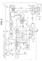
- Fig. 3 is a block diagram of the configuration of a recording/reproducing apparatus 1 according to a first embodiment of the present invention.
- the recording/reproducing apparatus 1 for recording and reproducing data on a DVD-R or DVD-RW (hereinafter referred to as a DVD) will be described as an example.
- pre-pits containing address information etc. of the DVD 19 are previously formed on an information track for recording recording information.
- the address information on the DVD 19 is previously obtained by detecting the pre-pits. In this way, the recording position at which the recording information is to be recorded is detected.
- the recording/reproducing apparatus 1 comprises a pickup 2 as a recording resuming means, a reproducing amplifier 3, an RF signal decoder 4, an RF detector 5, a pre-pit signal decoder 6, a servo circuit 7, a spindle motor 8, a processor 9 as a detecting means, stopping means, storage means and recording resuming means, a write starting signal generator 10, an encoder 11 as a recording signal generating means, a power control circuit 13, a laser drive circuit 14, and an interface 15.
- the recording/reproducing apparatus 1 receives recording information Sdc input from an external host computer 16 through the interface 15.
- the encoder 11 comprises a buffer memory 12 as a buffer means.
- the pickup 2 comprising a laser diode, a polarization beam splitter, an objective lens, a photo detector, etc. (not shown), irradiates a light beam B on the information recording surface of the DVD 19 based on the laser driving signal Sd1.
- the pickup 2 detects pre-pits based on the reflected light of the light beam B and records an encoding signal Sre to be recorded. If there is some information already recorded, the recorded information is detected based on the reflected light of the light beam B.
- the reproducing amplifier 3 amplifies a detecting signal Sdt which contains information corresponding to the pre-pit output from the pickup 2, generates a pre-pit signal Spp corresponding to the pre-pit, and outputs an amplified signal Sp which corresponds to the recording information which is already recorded.
- the decoder 4 decodes the amplified signal Sp by performing 8-16 demodulation and de-interleave on the amplified signal Sp to generate a demodulating signal Sdm and a servo demodulating signal Ssd.
- the RF detector 5 detects an RF signal from the amplified signal Sp and supplies the detected RF signal Sdr to the processor 9.
- the pre-pit signal decoder 6 decodes the pre-pit signal Spp to generate a demodulated pre-pit signal Spd.
- the servo circuit 7 generates a pickup servo signal Ssp for focus servo control and tracking servo control for the pickup 2 based on the demodulated pre-pit signal Spd, a wobble signal Swb, and a servo demodulating signal Ssd.
- the servo circuit 7 also generates a spindle servo signal Sss for servo control of the rotation of the spindle motor 8 for rotating the DVD 19, and then outputs the generated signals.
- the processor 9 Keeping pace with such operation, the processor 9 generates a recording trigger control signal Stc based on the pre-pit signal Spd and the detected RF signal Sdr to send it to the write starting signal generator 10. The processor 9 sends and receives a drive control data signal Scd to and from the interface 15. The processor 9 controls the overall recording/reproducing operation of the recording/reproducing apparatus 1.
- the interface 15 performs the interface operation for the recording information Sr sent from the host computer 16 for use by the recording/reproducing apparatus 1 under the control of the processor 9, and outputs the recording information Sr to the encoder 11.
- the encoder 11 comprises an ECC generator, an 8-16 demodulator, a scrambler, and a buffer memory 12 (which are not shown), and forms an ECC block 30 by adding an ECC internal code 31 and an ECC external code 32 to the recording information Sr.
- the encoder 11 performs the processes of interleave, 8-16 demodulation, and scrambling on the ECC block 30 to generate an encoding signal Sre.
- the buffer memory 12 contained in the encoder 11 temporarily stores the recording information Sr from the host computer 16 based on a buffer control signal Sc from the processor 9, and outputs the recording information Sr at a reading speed corresponding to the recording speed at which the pickup 2 records the encoding signal Sre onto the DVD 19.
- the power control circuit 13 generates and outputs a driving signal Sd for controlling the output of the laser diode (not shown) in the pickup 2 based on the encoding signal Sre.
- the laser drive circuit 14 supplies the laser driving signal Sd1 to the pickup 2 for driving the laser diode so as to make it emit the light beam B based on the driving signal Sd.
- the above-mentioned recording/reproducing apparatus 1 is also capable of reproducing information recorded on the DVD 19.
- a reproducing signal Sot is supplied to an external apparatus through the processor 9 based on the demodulated signal Sdm.
- the control data zone which is the control data recording area of the DVD 19, is prewritten at the time of shipment. In the prewritten section, an RF signal can be read but a pre-pit is comparatively hard to read.
- the end of the control data zone that is, the portion adjacent to the extra border zone (for example, 16 ECC blocks) is an unreadable embossed section where an RF signal cannot be read but a pre-pit signal is obtainable. In this case, the remaining part of the control data zone (that is, 176 ECC blocks) is made to be a readable embossed section.
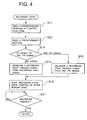
- the recording procedure of the above-mentioned recording/reproducing apparatus 1 will be described in detail with reference to the flowchart shown in Fig. 4.
- the recording operation is executed under the control of the processor 9 when recording is carried out on the extra border zone.
- the processor 9 executes control for seeking a predetermined position in the control data zone based on the address of the control data zone (Step S11). As shown in Fig. 7, the predetermined position is the start position of a predetermined section (for example, 8 ECC blocks) adjacent to the extra border zone. The predetermined section is then read (Step S12). The processor 9 determines whether the RF data signal (hereinafter, also simply referred to as an RF signal) is detected or a pre-pit signal is detected in the read signal based on the signals from the RF signal decoder 4, the RF detector 5, and the pre-pit signal decoder 6 (Step S13).
- the RF data signal hereinafter, also simply referred to as an RF signal
- a synchronizing signal (trigger signal) indicating the recording start timing is generated from the recorded data signal (RF signal) in the write starting signal generator 10 (Step S14). If it is determined that a pre-pit signal is detected, a record starting trigger signal is generated from the pre-pit signal in the write starting signal generator 10 (Step S15).
- the processor 9 starts recording from the start position of the extra border zone at the recording start timing while confirming that synchronization is maintained (Step S16).
- management information data such as border information (extra border information) showing addresses regarding the delimiting positions of the recording data in the data area, copies of the RMD (Recording Management Data), etc, are recorded. Recording is performed all over the extra border zone so as not to leave any unrecorded area in order to make tracing possible when the disk is reproduced.
- Step S17 Whether or not all-over recording is completed is determined.
- control data zone is prewritten or a readable embossed section, recording in the area adjacent to this zone is possible.
- recording in the extra border zone is performed after a detecting signal from a predetermined section of the control data zone is determined.
- the above-mentioned procedure need not be performed before recording the recording information data (audio data, video data, etc.) in the data area, but may be performed after recording the recording information data.
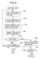
- Figs. 8 and 9 are flowcharts of the recording procedure of a recording/reproducing apparatus 1 according to a second embodiment of the present invention.
- the processor 9 executes control for seeking a predetermined position in the control data zone based on the address of the control data zone (Step S21).
- the predetermined position is the start position of a predetermined section adjacent to the extra border zone, similar to the case of the first embodiment.
- the predetermined section is then read and the read signal is detected (Step S22).
- the processor 9 instructs the write starting signal generator 10 to generate a record starting trigger signal from the RF signal of the read signal (Step S23).
- the processor 9 waits for a recording start timing while confirming that synchronization is maintained. If synchronization is maintained, the processor 9 requires a record starting trigger signal from the write starting signal generator 10 at a predetermined timing (Step S24). Whether or not recording start is possible is then determined (Step S25). More specifically, in the determining step, recording start is determined to be possible if a record starting trigger signal is output from the write starting signal generator 10 in response to the output request for a trigger signal. On the other hand, recording start is determined to be impossible if a clock is not obtained based on the signal from the RF signal decoder 4 in the write starting signal generator 10 and no record starting trigger signal is output from the write starting signal generator 10.
- step S25 if it is so determined that recording start is possible, recording is started from the start position of the extra border zone based on the record starting trigger signal (Step S26). Whether or not recording is finished is determined (Step S27). When recording is finished, control is returned to the main routine.
- step S25 if it is determined that recording start is impossible, the number of retries is determined (Step S28). If the number of retries has not reached a predetermined number, control goes back to step S21 and the above-mentioned procedure is repeated. If the number of retries exceeds the predetermined number, control goes to step S29.
- the processor 9 executes control for seeking a predetermined position in the control data zone based on the address of the control data zone (Step S29).
- the predetermined section is then read and the read signal is detected (Step S30).
- the processor 9 instructs the write starting signal generator 10 to generate a record starting trigger signal from the pre-pit signal of the read signal (Step S31).
- the processor 9 waits for a recording start timing while confirming that synchronization is maintained. If synchronization is maintained, the processor 9 requires a record starting trigger signal from the write starting signal generator 10 at the predetermined timing (Step S32). Whether or not recording start is possible is determined next (Step S33). In this determining step, whether or not a record starting trigger signal is output from the write starting signal generator 10 in response to the output request for a trigger signal is determined in the same way as that mentioned above. Recording start is determined to be impossible if a clock is not obtained in the write starting signal generator 10 based on the pre-pit signal from the pre-pit signal decoder 6 and no record starting trigger signal is output from the write starting signal generator 10.
- step S33 if it is determined that recording start is possible, recording is started from the start position of the extra border zone in response to the record starting trigger signal (Step S34). Whether or not recording is finished is determined (Step S35). When recording is finished, control is returned to the main routine.
- step S33 if it is determined that recording start is impossible, the number of retries is determined (Step S36). If the number of retries has not reached a predetermined number, control goes back to step S29 and the above-mentioned procedure is repeated. If the number of retries exceeds the predetermined number, a predetermined error handling process is executed (Step S37) and control is returned to the main routine.
- control data zone is prewritten or even though it is formed by a readable embossed area, recording in the area adjacent to this zone is possible.
- recording is retried for a predetermined number of times if recording start is determined to be impossible, and the method for generating a trigger signal is switched if recording is still impossible even after retrying for the predetermined number of times (that is, switched from trigger signal generation by means of an RF signal to trigger signal generation by means of a pre-pit signal).
- the present invention is not limited to this case.
- a method for switching from trigger signal generation by means of a pre-pit signal to trigger signal generation by means of an RF signal may be used. It is also possible to switch to another method for generating a trigger signal when recording is impossible and to further change the trigger signal generating method if recording is still impossible, without performing recording retrying by the same trigger signal generating method.
- disc identification information which indicates that the control data zone is prewritten or the control data zone is formed on a readable embossed area is recorded at a predetermined position in the lead-in area of the disc 19.
- the predetermined position is a "Part version field" in field ID1 of the pre-pit where "0100b” designates a prewritten disc and "0101b” designates a disc in which embossing is used for writing.
- the recording/reproducing apparatus may be so configured that it further includes a means for identifying the predetermined position where the disc identification information is recorded, and a means for obtaining the disc identification information from the predetermined position to determine the content of the disc identification information.
- a recording/reproducing apparatus which can write data on discs of both types can be achieved by checking the data in an area where the disc identification information is recorded and selecting a trigger signal generation method for the writing process immediately after the control data zone based on the results of the data check.
- whether or not an RF data signal was detected by reading a predetermined section can be determined by whether or not recorded ID (identification) information can be read. Specifically, if the ID read number in the predetermined section is counted and the ID number exceeds a certain number, it can be determined that the RF signal was read out. That is, it is determined that the predetermined section is a prewritten area and such area can be written after obtaining the synchronizing information from the RF signal.
- the error rate of the pre-pit of a signal read out is less than a predetermined value, it can be determined that a pre-pit signal could be detected by reading the predetermined section and read out. Or, any value corresponding to the error rate of the pre-pit can be used. For example, if the read number of the pre-pit of a certain time period is above a certain value, it can be determined that the pre-pit signal was read out.
- whether a signal is an RF signal or a pre-pit signal can be identified by a conventional signal processing process, for example, by comparing the intensity of the detected signal with a predetermined threshold value, or by identifying a characteristic value such as the frequency of the detected signal, pulse width, etc.
- a DVD-R is used as an example of the optical recording medium.
- the present invention is not limited to DVD-Rs, but is applicable to any other optical recording medium.
- a recording/reproducing apparatus which can record and reproduce data regardless of the control data zone forming procedure of the disc can be achieved.
Landscapes
- Engineering & Computer Science (AREA)
- Signal Processing (AREA)
- Optical Recording Or Reproduction (AREA)
- Signal Processing For Digital Recording And Reproducing (AREA)
Abstract
Description
Claims (8)
- An optical recording apparatus for recording an information data signal on an optical recording medium, comprising:a position identifying portion for identifying the position of a control data recording area where control data regarding recording of said information data signal is recorded;a pre-pit signal detecting portion for reading a predetermined section of said control data recording area to detect a pre-pit signal from the read signal; anda generating portion for generating a recording synchronizing signal indicating recording start timing from said pre-pit signal.
- An optical recording apparatus for recording an information data signal on an optical recording medium, comprising:a position identifying portion for identifying the position of a control data recording area where control data regarding recording of said information data signal is recorded;an RF data signal detecting portion for reading a predetermined section of said control data recording area to detect an RF data signal from the read signal; anda generating portion for generating a recording synchronizing signal indicating recording start timing from said RF data signal.
- An optical recording apparatus for recording an information data signal on an optical recording medium, comprising:a position identifying portion for identifying the position of a control data recording area where control data regarding recording of said information data signal is recorded;a pre-pit signal detecting portion for reading a predetermined section of said control data recording area to detect detecting a pre-pit signal from the read signal;an RF data signal detecting portion for reading a predetermined section of said control data recording area to detect an RF data signal from the read signal; anda selecting portion for selecting either of said pre-pit signal detecting portion and said RF data signal detecting portion to generate a recording synchronizing signal indicating recording start timing from the detected signal.
- An optical recording apparatus according to claim 1, comprising a recording portion for recording predetermined management information in an area adjacent to said control data recording area in response to said recording synchronizing signal.
- An optical recording apparatus according to claim 1, wherein said predetermined section is positioned at the end of said control data recording area.
- A method for recording an information data signal on an optical recording medium, comprising the steps of:identifying the position of a control data recording area where control data regarding recording of said information data signal is recorded;detecting a pre-pit signal by reading a predetermined section of said control data recording area; andgenerating a recording synchronizing signal indicating recording start timing from said pre-pit signal.
- A method for recording an information data signal on an optical recording medium, comprising the steps of:identifying the position of a control data recording area where control data regarding recording of said information data signal is recorded;detecting an RF data signal by reading a predetermined section of said control data recording area; andgenerating a recording synchronizing signal indicating recording start timing from said RF data signal.
- A method for recording an information data signal on an optical recording medium, comprising the steps of:identifying the position of a control data recording area where control data regarding recording of said information data signal is recorded;detecting a pre-pit signal by reading a predetermined section of said control data recording area;detecting an RF data signal by reading a predetermined section of said control data recording area; andexecuting either one of the step of detecting a pre-pit signal and the step of detecting an RF data signal to generate a recording synchronizing signal indicating recording start timing from the detected signal.
Applications Claiming Priority (2)
| Application Number | Priority Date | Filing Date | Title |
|---|---|---|---|
| JP2000344147A JP2002150557A (en) | 2000-11-10 | 2000-11-10 | Recording device and recording method for optical recording medium |
| JP2000344147 | 2000-11-10 |
Publications (2)
| Publication Number | Publication Date |
|---|---|
| EP1209679A2 true EP1209679A2 (en) | 2002-05-29 |
| EP1209679A3 EP1209679A3 (en) | 2002-06-05 |
Family
ID=18818396
Family Applications (1)
| Application Number | Title | Priority Date | Filing Date |
|---|---|---|---|
| EP01126617A Withdrawn EP1209679A3 (en) | 2000-11-10 | 2001-11-07 | Recording apparatus and method for optical recording medium |
Country Status (3)
| Country | Link |
|---|---|
| US (1) | US20020057634A1 (en) |
| EP (1) | EP1209679A3 (en) |
| JP (1) | JP2002150557A (en) |
Cited By (3)
| Publication number | Priority date | Publication date | Assignee | Title |
|---|---|---|---|---|
| WO2003075265A3 (en) * | 2002-03-05 | 2003-11-13 | Koninkl Philips Electronics Nv | Device, record carrier and method for recording information |
| EP1300837A3 (en) * | 2001-10-02 | 2004-12-01 | Pioneer Corporation | Disk reproducer |
| EP1376551A3 (en) * | 2002-06-19 | 2005-01-19 | Pioneer Corporation | Information recording apparatus and control method thereof |
Families Citing this family (1)
| Publication number | Priority date | Publication date | Assignee | Title |
|---|---|---|---|---|
| KR100750109B1 (en) * | 2003-02-15 | 2007-08-21 | 삼성전자주식회사 | Information storage medium |
Family Cites Families (11)
| Publication number | Priority date | Publication date | Assignee | Title |
|---|---|---|---|---|
| JP2667522B2 (en) * | 1989-07-06 | 1997-10-27 | 株式会社日立製作所 | Optical disk drive |
| US5274623A (en) * | 1990-07-19 | 1993-12-28 | Fuji Photo Film Co., Ltd. | Information recording medium having high modulation degree |
| JPH04301222A (en) * | 1991-03-28 | 1992-10-23 | Toshiba Corp | Disk reproducing device |
| JPH10124873A (en) * | 1996-10-23 | 1998-05-15 | Sony Corp | Signal recording method and signal recording / reproducing device |
| JP3555055B2 (en) * | 1997-04-07 | 2004-08-18 | パイオニア株式会社 | Prepit detection device and information recording device |
| JP3831063B2 (en) * | 1997-04-25 | 2006-10-11 | パイオニア株式会社 | Optical disc discrimination device |
| US5936493A (en) * | 1997-11-24 | 1999-08-10 | Raytheon Company | Low cost, one-shot switch waveguide window |
| JPH11238315A (en) * | 1998-02-19 | 1999-08-31 | Pioneer Electron Corp | Information recording device and initializing method |
| JP4102483B2 (en) * | 1998-06-02 | 2008-06-18 | パイオニア株式会社 | Information recording device |
| JP4040780B2 (en) * | 1998-12-28 | 2008-01-30 | パイオニア株式会社 | Recording timing setting system and information recording system |
| JP3979560B2 (en) * | 2000-08-24 | 2007-09-19 | パイオニア株式会社 | Disc type discrimination method and reproducing apparatus thereof |
-
2000
- 2000-11-10 JP JP2000344147A patent/JP2002150557A/en not_active Abandoned
-
2001
- 2001-11-07 EP EP01126617A patent/EP1209679A3/en not_active Withdrawn
- 2001-11-13 US US09/987,085 patent/US20020057634A1/en not_active Abandoned
Non-Patent Citations (1)
| Title |
|---|
| None * |
Cited By (5)
| Publication number | Priority date | Publication date | Assignee | Title |
|---|---|---|---|---|
| EP1300837A3 (en) * | 2001-10-02 | 2004-12-01 | Pioneer Corporation | Disk reproducer |
| WO2003075265A3 (en) * | 2002-03-05 | 2003-11-13 | Koninkl Philips Electronics Nv | Device, record carrier and method for recording information |
| EP1376551A3 (en) * | 2002-06-19 | 2005-01-19 | Pioneer Corporation | Information recording apparatus and control method thereof |
| US7126893B2 (en) | 2002-06-19 | 2006-10-24 | Pioneer Corporation | Information recording apparatus and control method thereof |
| CN1320530C (en) * | 2002-06-19 | 2007-06-06 | 日本先锋公司 | Data recording device and its control |
Also Published As
| Publication number | Publication date |
|---|---|
| JP2002150557A (en) | 2002-05-24 |
| US20020057634A1 (en) | 2002-05-16 |
| EP1209679A3 (en) | 2002-06-05 |
Similar Documents
| Publication | Publication Date | Title |
|---|---|---|
| JP4588280B2 (en) | Method for tracking defective sectors in rewritable disc media | |
| JP2000331412A (en) | Information recording medium manufacturing device, information recording medium, information recorder and information recording method | |
| KR20040039784A (en) | Optical disc having tracking polarity information, apparatus and method for recording and reproducing the same thereon | |
| US6212141B1 (en) | Information recording apparatus and method | |
| EP1517323A2 (en) | Optical disk apparatus and method for controlling the same | |
| KR100419159B1 (en) | Servo control apparatus, servo control method and information reproducing apparatus | |
| US20020057634A1 (en) | Recording apparatus and method for optical recording medium | |
| KR100576661B1 (en) | Information recording method and optical disk device | |
| KR100595496B1 (en) | Digital Information Storage Media and Its Prevention Methods | |
| RU2314579C2 (en) | Optical recording data carrier, method of data recording/playing from/to optical recording carrier and device for recording/playing dta onto/from recording data carrier | |
| KR100671863B1 (en) | Optical disc, information recording and reproducing apparatus, information recording and reproducing method, information reproducing apparatus and information reproducing method | |
| JP4175356B2 (en) | Optical disk recording device | |
| KR100643449B1 (en) | Determination method of optical disc and copy-protected optical disc | |
| KR20040075216A (en) | Method for controlling record of a optical disc and apparatus thereof | |
| JP2004288230A (en) | Information recording method and information recording device | |
| JP3734825B2 (en) | Information recording medium manufacturing apparatus, information recording method, and information recording medium | |
| JP4111807B2 (en) | Information recording method, disk device, and information recording device | |
| US7660215B2 (en) | Method and apparatus for writing data to optical disc | |
| JP3819400B2 (en) | Information recording medium manufacturing apparatus, information recording medium manufacturing method, and information recording medium | |
| KR100775149B1 (en) | Playback-only recording media and data reproduction method | |
| KR19980047090A (en) | Bad sector search method and disc management method of recordable disc | |
| JP2010514086A (en) | Reliable video recording on optical discs | |
| US20060280053A1 (en) | Disc loading method for optical disc apparatus | |
| JP2005085341A (en) | Information recording medium, information recording and reproducing device, method for recording information, and information recording program | |
| KR20060067340A (en) | Device and method for correcting defects of write once optical discs |
Legal Events
| Date | Code | Title | Description |
|---|---|---|---|
| PUAI | Public reference made under article 153(3) epc to a published international application that has entered the european phase |
Free format text: ORIGINAL CODE: 0009012 |
|
| PUAL | Search report despatched |
Free format text: ORIGINAL CODE: 0009013 |
|
| AK | Designated contracting states |
Kind code of ref document: A2 Designated state(s): AT BE CH CY DE DK ES FI FR GB GR IE IT LI LU MC NL PT SE TR |
|
| AX | Request for extension of the european patent |
Free format text: AL;LT;LV;MK;RO;SI |
|
| AK | Designated contracting states |
Kind code of ref document: A3 Designated state(s): AT BE CH CY DE DK ES FI FR GB GR IE IT LI LU MC NL PT SE TR |
|
| AX | Request for extension of the european patent |
Free format text: AL;LT;LV;MK;RO;SI |
|
| 17P | Request for examination filed |
Effective date: 20020821 |
|
| AKX | Designation fees paid |
Designated state(s): DE FR GB |
|
| 17Q | First examination report despatched |
Effective date: 20061215 |
|
| 18D | Application deemed to be withdrawn |
Effective date: 20060418 |
|
| STAA | Information on the status of an ep patent application or granted ep patent |
Free format text: STATUS: THE APPLICATION IS DEEMED TO BE WITHDRAWN |
|
| R18D | Application deemed to be withdrawn (corrected) |
Effective date: 20070426 |