EP1209521A1 - Apparatus for packaging photographic pictures - Google Patents
Apparatus for packaging photographic pictures Download PDFInfo
- Publication number
- EP1209521A1 EP1209521A1 EP01127690A EP01127690A EP1209521A1 EP 1209521 A1 EP1209521 A1 EP 1209521A1 EP 01127690 A EP01127690 A EP 01127690A EP 01127690 A EP01127690 A EP 01127690A EP 1209521 A1 EP1209521 A1 EP 1209521A1
- Authority
- EP
- European Patent Office
- Prior art keywords
- index print
- conveying device
- picture
- air
- Prior art date
- Legal status (The legal status is an assumption and is not a legal conclusion. Google has not performed a legal analysis and makes no representation as to the accuracy of the status listed.)
- Granted
Links
Images


Classifications
-
- G—PHYSICS
- G03—PHOTOGRAPHY; CINEMATOGRAPHY; ANALOGOUS TECHNIQUES USING WAVES OTHER THAN OPTICAL WAVES; ELECTROGRAPHY; HOLOGRAPHY
- G03D—APPARATUS FOR PROCESSING EXPOSED PHOTOGRAPHIC MATERIALS; ACCESSORIES THEREFOR
- G03D15/00—Apparatus for treating processed material
- G03D15/001—Counting; Classifying; Marking
- G03D15/005—Order systems, e.g. printsorter
-
- G—PHYSICS
- G03—PHOTOGRAPHY; CINEMATOGRAPHY; ANALOGOUS TECHNIQUES USING WAVES OTHER THAN OPTICAL WAVES; ELECTROGRAPHY; HOLOGRAPHY
- G03D—APPARATUS FOR PROCESSING EXPOSED PHOTOGRAPHIC MATERIALS; ACCESSORIES THEREFOR
- G03D15/00—Apparatus for treating processed material
- G03D15/001—Counting; Classifying; Marking
Definitions
- the invention concerns an apparatus for introducing photographic pictures and film strips, and in particular index prints, into a job pouch that has a picture pocket and a film-strip pocket, comprising one conveying device in each case for the pictures, for the film strips, and for the index print, and a support plate for the job pouch that is to be loaded.
- index print is simply deposited onto the picture/film pocket loaded with pictures and film strips, before the closure flap is flipped closed over the index print and this unit is then placed in the customer job pouch.
- a new job pouch with a modified configuration has now been introduced in the territory of the European Union.
- This new job pouch combines the picture/film pouch and the customer job pouch into a one-piece job pouch.
- the closure flap of this new job pouch is equipped with an adhesive closure.
- the index print can no longer be deposited between the closure flap and the pockets loaded with pictures and film strips, since in that location it would interfere with the adhesive closure.
- This circumstance makes it necessary for the index print also to be housed inside the job pouch in the pocket for the pictures. An operation of this kind is not possible with the known machine that is being used.
- the conveying device for the index print is movable from a horizontal starting position in order to receive the index print, into a vertical position, holding the job pouch on the support plate, in order to deliver the index print into the picture pocket; and that the upper side of the picture pocket can be acted upon by a flow of compressed air.
- the conveying device is configured such that the one for the index print has a frame and a deposition plate, pivotably mounted in the latter, having a holding device for the index print; that a compressed-air apparatus directed toward the support plate is provided on the conveying device; that the latter is movable about a shaft out of its horizontal starting position into its vertical position and can be lowered onto the support plate; and that in order to deliver the index print into the picture pocket of the job pouch, the deposition plate is pivotable out of the vertical position about a pivot axis into an inclined oblique position.
- the deposition plate With the conveying device in this vertical position, the deposition plate is located opposite the opening of the picture pocket of a job pouch lying on the support plate; as a consequence of a flow of air delivered by the compressed-air apparatus, the picture pocket is opened and held open on the one hand because of the negative pressure generated by the flow of air on the upper side of the picture pocket, and on the other hand by the flow of air reflected from the deposition plate and penetrating into the picture pocket.
- the deposition plate Upon delivery of the flow of compressed air by the compressed-air apparatus, the deposition plate is pivotable out of its vertical position into an oblique position inclined with respect to the opening of the picture pocket, the deposition plate having a bracket, extending almost over the width of the picture pocket, that engages into the picture pocket when the deposition plate is in the pivoted oblique position.
- the index print can be reliably placed into the picture pocket even with the packaging machines hitherto used for pictures and film strip, with no damage to the pictures already present in the job pocket.
- a conveying device 100 for conveying an index print into a customer job pouch 12 already loaded with pictures and film strips comprises a frame 10 in which a deposition plate 11 is mounted, pivotably by way of a compressed-air cylinder 14, about a fulcrum 13.
- a clamping plate 15 is arranged on deposition plate 11 in such a way that by way of articulated pieces 17 mounted articulatedly on frame 10, it can on the one hand be lifted away from deposition plate 11 in order to deposit an index print 25 on deposition plate 11, and on the other hand can be lowered onto deposition plate 11 in order to clamp index print 25 in place.
- Articulated pieces 17 are acted upon and moved by a linear actuator cylinder 18.
- a slider 16 guided on deposition plate 11 in longitudinal slots 31, for removing index print 25 from deposition plate 11.
- Slider 16 is movable by way of a pusher cylinder (not depicted) via a crank linkage 35.
- bracket 24 Provided at the free end of deposition plate 11 and extending over the latter's width is a bracket 24 whose width is adapted to the internal width of a picture pocket 22 of job pouch 12.
- the emission direction of nozzle 33 is directed, at an acute angle that can be between 25 and 85 degrees, frontally toward deposition plate 11.
- a support plate 30 is provided inside the packaging machine in order to support a job pouch 12 that is to be loaded with pictures, film strips, and index print 25.
- Job pouch 12 comprises picture pocket 22, a film pocket 32, and a closure flap 34.
- An adhesive closure 36 for sealing job pouch 12 is provided between closure flap 34 and the side of job pouch 12 on which picture pocket 22 and film pocket 32 are arranged.
- Conveying device 100 is arranged so as to pivot about a shaft 23 out of its horizontal starting position for receiving an index print 25 into its vertical position for delivering index print 25 to job pouch 12.
- Frame 10 with deposition plate 11 of conveying device 100 is then rotated 90 degrees about shaft 23 into a vertical position (see Fig. 2), by way of a drive (not depicted) engaging on a pivot lever 28, and lowered onto support plate 30.
- the vertical movement of the conveying device is accomplished by way of a gated guide that is joined to a flange 27 mounted immovably on shaft 23. With conveying device 100 in the vertical position, job pouch 12 is held on support plate 30 by frame 10.
- Deposition plate 11 then returns from the inclined oblique position into its vertical position, and conveying device 100 returns from its vertical position into its horizontal starting position, in order to receive the next index print 25.
- Closure flap 34 is folded over upper side 21, i.e. over picture pocket 22 and film pocket 32, and job pouch 12 is thereby sealed by way of adhesive closure 36. The loaded job pocket 12 is then transported off to an output container.
- the decisive feature of the subject matter of the invention is the fact that it is possible, by way of a negative pressure generated by a flow of compressed air, to open the already loaded picture pocket 22 to such an extent that bracket 24 can engage into picture pocket 22 and open the latter sufficiently wide that index print 25 can be added, subsequently and additionally, to the pictures already present in picture pocket 22.
Landscapes
- Physics & Mathematics (AREA)
- General Physics & Mathematics (AREA)
- Photographic Processing Devices Using Wet Methods (AREA)
- Supplying Of Containers To The Packaging Station (AREA)
Abstract
Description
- The invention concerns an apparatus for introducing photographic pictures and film strips, and in particular index prints, into a job pouch that has a picture pocket and a film-strip pocket, comprising one conveying device in each case for the pictures, for the film strips, and for the index print, and a support plate for the job pouch that is to be loaded.
- Once a customer's photographic film has been developed, enlargements in the form of pictures are made of the individual photographic images. The pictures, cut into individual pictures, are deposited in a picture/film pocket in a separate picture compartment. The film, cut into strips, is also housed in the same picture/film pocket in a separate film-strip compartment. The two compartments are then covered with a single closure flap hinged on the picture/film pocket. The picture/film pocket is then placed into a customer job pouch and delivered to the customer, for example, via a photo shop.
- It has recently become customary to add to the pictures and image strips in the picture/film pocket a picture-like "index print," which shows all the photographic images present on the film in a small format, in a positive depiction, and in an organized arrangement. This has the advantage that in the case of a negative film, the customer is better able to recognize the images he or she has taken, and can more conveniently and reliably select them so as to reorder prints.
- These picture and film strip packaging operations are all performed automatically. In the context of presently known packaging machines, the index print is simply deposited onto the picture/film pocket loaded with pictures and film strips, before the closure flap is flipped closed over the index print and this unit is then placed in the customer job pouch.
- A new job pouch with a modified configuration has now been introduced in the territory of the European Union. This new job pouch combines the picture/film pouch and the customer job pouch into a one-piece job pouch. In addition, the closure flap of this new job pouch is equipped with an adhesive closure. As a result of this configuration of the job pouch, the index print can no longer be deposited between the closure flap and the pockets loaded with pictures and film strips, since in that location it would interfere with the adhesive closure. This circumstance makes it necessary for the index print also to be housed inside the job pouch in the pocket for the pictures. An operation of this kind is not possible with the known machine that is being used.
- It is therefore the object of the invention to reconfigure the packaging machine used for loading the old-format picture/film pocket and job pocket, without costly effort, in such a way that it can be reliably and economically used to load the new EU job pouch.
- This is achieved, according to the present invention, in that the conveying device for the index print is movable from a horizontal starting position in order to receive the index print, into a vertical position, holding the job pouch on the support plate, in order to deliver the index print into the picture pocket; and that the upper side of the picture pocket can be acted upon by a flow of compressed air.
- In detail, the conveying device is configured such that the one for the index print has a frame and a deposition plate, pivotably mounted in the latter, having a holding device for the index print; that a compressed-air apparatus directed toward the support plate is provided on the conveying device; that the latter is movable about a shaft out of its horizontal starting position into its vertical position and can be lowered onto the support plate; and that in order to deliver the index print into the picture pocket of the job pouch, the deposition plate is pivotable out of the vertical position about a pivot axis into an inclined oblique position.
- With the conveying device in this vertical position, the deposition plate is located opposite the opening of the picture pocket of a job pouch lying on the support plate; as a consequence of a flow of air delivered by the compressed-air apparatus, the picture pocket is opened and held open on the one hand because of the negative pressure generated by the flow of air on the upper side of the picture pocket, and on the other hand by the flow of air reflected from the deposition plate and penetrating into the picture pocket.
- Upon delivery of the flow of compressed air by the compressed-air apparatus, the deposition plate is pivotable out of its vertical position into an oblique position inclined with respect to the opening of the picture pocket, the deposition plate having a bracket, extending almost over the width of the picture pocket, that engages into the picture pocket when the deposition plate is in the pivoted oblique position.
- With this simply constructed and retrofittable conveying device, the index print can be reliably placed into the picture pocket even with the packaging machines hitherto used for pictures and film strip, with no damage to the pictures already present in the job pocket.
- Further features and advantages are evident from the description of an exemplary embodiment of the invention that is depicted in the drawings, and from the further dependent claims.
- In the drawings:
- Fig. 1
- shows a view of the conveying device according to the present invention in its upper, horizontal starting position;
- Fig. 2
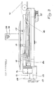
- shows a view of the conveying device of Fig. 1 in its lower, vertical position;
- Fig. 3
- shows a view in the direction of arrow "A" of the conveying device of Fig. 1; and
- Fig. 4
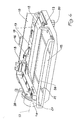
- shows the conveying device of Fig. 1 in a perspective depiction.
- The exemplary embodiment depicted in the drawings of a
conveying device 100 for conveying an index print into acustomer job pouch 12 already loaded with pictures and film strips comprises aframe 10 in which adeposition plate 11 is mounted, pivotably by way of a compressed-air cylinder 14, about afulcrum 13. Aclamping plate 15 is arranged ondeposition plate 11 in such a way that by way of articulatedpieces 17 mounted articulatedly onframe 10, it can on the one hand be lifted away fromdeposition plate 11 in order to deposit anindex print 25 ondeposition plate 11, and on the other hand can be lowered ontodeposition plate 11 in order to clampindex print 25 in place.Articulated pieces 17 are acted upon and moved by alinear actuator cylinder 18. Also provided is aslider 16, guided ondeposition plate 11 inlongitudinal slots 31, for removingindex print 25 fromdeposition plate 11.Slider 16 is movable by way of a pusher cylinder (not depicted) via acrank linkage 35. - Provided at the free end of
deposition plate 11 and extending over the latter's width is abracket 24 whose width is adapted to the internal width of apicture pocket 22 ofjob pouch 12. - Lastly, an
extension arm 19, at whose free end sits anozzle 33 of a compressed-air apparatus 20, is mounted onframe 10. The emission direction ofnozzle 33 is directed, at an acute angle that can be between 25 and 85 degrees, frontally towarddeposition plate 11. - A
support plate 30 is provided inside the packaging machine in order to support ajob pouch 12 that is to be loaded with pictures, film strips, andindex print 25. -
Job pouch 12 comprisespicture pocket 22, afilm pocket 32, and aclosure flap 34. Anadhesive closure 36 forsealing job pouch 12 is provided betweenclosure flap 34 and the side ofjob pouch 12 on whichpicture pocket 22 andfilm pocket 32 are arranged.
Conveyingdevice 100 is arranged so as to pivot about ashaft 23 out of its horizontal starting position for receiving anindex print 25 into its vertical position for deliveringindex print 25 tojob pouch 12. - The manner of operation of the conveying device for the index print within the overall apparatus is as follows:
- While the developed and cut pictures are being conveyed to picture
pocket 22, and the film (cut into strips) intofilm pocket 32,conveying device 100 is in its horizontal starting position as depicted in Figs. 1 and 3. In this position,clamping plate 15 is in its opened state and anindex print 25 can be conveyed via atransport apparatus 40 to conveyingdevice 100, and deposited ondeposition plate 11. Clampingplate 15 is then lowered by way oflinear actuator cylinder 18 back ontodeposition plate 11, and clamps index print 25 in place on the latter. -
-
Frame 10 withdeposition plate 11 ofconveying device 100 is then rotated 90 degrees aboutshaft 23 into a vertical position (see Fig. 2), by way of a drive (not depicted) engaging on apivot lever 28, and lowered ontosupport plate 30. The vertical movement of the conveying device is accomplished by way of a gated guide that is joined to aflange 27 mounted immovably onshaft 23. Withconveying device 100 in the vertical position,job pouch 12 is held onsupport plate 30 byframe 10. - With
conveying device 100 in this position, compressed-air apparatus 20 is put into operation, and a stream of compressed air is blown at an acute angle throughnozzle 33 towarddeposition plate 11. This stream of compressed air generates a negative pressure in the region ofupper side 21 ofpicture pocket 22, in such a way thatpicture pocket 22 opens. As a result of the air which is reflected from deposition plate 11 (and from index print 25) and penetrates into the openedpicture pocket 22, the latter is opened even further. At the same time,deposition plate 11, driven by compressed-air cylinder 14, is pivoted out of its vertical position into an oblique position inclined with respect to supportplate 30, in whichbracket 24 engages intopicture pocket 22 and completely opens the latter, as depicted with dot-dash lines in Fig. 2. After the lifting ofclamping plate 15,slider 16 is then moved in the direction ofbracket 24 bycrank linkage 35 that is also driven by a compressed-air cylinder (not depicted), andindex print 25 is slid through underbracket 24 intopicture pocket 22. -
Deposition plate 11 then returns from the inclined oblique position into its vertical position, and conveyingdevice 100 returns from its vertical position into its horizontal starting position, in order to receive thenext index print 25. - Closure
flap 34 is folded overupper side 21, i.e. overpicture pocket 22 andfilm pocket 32, andjob pouch 12 is thereby sealed by way ofadhesive closure 36. The loadedjob pocket 12 is then transported off to an output container. - The decisive feature of the subject matter of the invention is the fact that it is possible, by way of a negative pressure generated by a flow of compressed air, to open the already loaded
picture pocket 22 to such an extent thatbracket 24 can engage intopicture pocket 22 and open the latter sufficiently wide thatindex print 25 can be added, subsequently and additionally, to the pictures already present inpicture pocket 22. - This simply constructed and reliably operating apparatus makes it possible to refit costly packaging machines for pictures and films, quickly and economically, in such a way that they can also process new, reconfigured EU job pockets.
-
- 10
- Frame
- 11
- Deposition plate for index print
- 12
- Job pouch
- 13
- fulcrum
- 14
- Compressed-air cylinder
- 15
- Clamping plate for index print
- 16
- Slider
- 17
- Articulated piece
- 18
- Linear actuator cylinder for clamping plate
- 19
- Extension arm
- 20
- Compressed-air apparatus
- 21
- Upper side
- 22
- Picture pocket
- 23
- Shaft
- 24
- Bracket
- 25
- Index print
- 27
- Flange
- 28
- Pivot lever
- 30
- Support plate
- 31
- Longitudinal slot
- 32
- Film pocket
- 33
- Nozzle
- 34
- Closure flap
- 35
- Crank linkage
- 36
- Adhesive closure
- 40
- Transport device
- 100
- Conveying device
Claims (12)
- An apparatus for introducing photographic pictures and film strips, and in particular index prints, into a job pouch that has a picture pocket and a film-strip pocket, comprising one conveying device in each case for the pictures, for the film strips, and for the index print, and a support plate for the job pouch that is to be loaded, characterized in that the conveying device (100) for the index print (25) is movable from a horizontal starting position in order to receive the index print (25), into a vertical position, holding the job pouch (12) on the support plate (30), in order to deliver the index print (25) into the picture pocket (22); and that the upper side (21) of the picture pocket (22) can be acted upon by a flow of compressed air.
- The apparatus as defined in Claim 1, characterized in that the conveying device (100) for the index print (25) has a frame (10) and a deposition plate (11), pivotably mounted in the latter, having a holding device (15) for the index print (25); that a compressed-air apparatus (20) directed toward the deposition plate (11) is provided on the conveying device (100); that the latter is movable about a shaft (23) out of its horizontal starting position into its vertical position and can be lowered onto the support plate (30); and that in order to deliver the index print (25) into the picture pocket (22) of the job pouch (12), the deposition plate (11) is pivotable out of the vertical position about a fulcrum (13) into an inclined oblique position.
- The apparatus as defined in Claims 1 and 2, characterized in that in its vertical position, the conveying device (100) lies with its deposition plate (11) opposite the opening of the picture pocket (22) of a job pouch (12) lying on the support plate (30); and that as a consequence of a flow of air delivered by the compressed-air apparatus (20), the picture pocket (22) is opened and held open on the one hand because of the negative pressure generated by the flow of air on the upper side (21) of the picture pocket (22), and on the other hand by the flow of air reflected from the deposition plate (11) and penetrating into the picture pocket (22).
- The apparatus as defined in Claims 1 through 3, characterized in that upon delivery of the flow of compressed air by the compressed-air apparatus (20), the deposition plate (11) is pivotable out of its vertical position into an oblique position inclined with respect to the opening of the picture pocket (22); and that the deposition plate (11) has a bracket (24), extending almost over the width of the picture pocket (22), that engages into the picture pocket (22) when the deposition plate (11) is in the pivoted oblique position.
- The apparatus as defined in Claim 4, characterized in that the bracket (24) for the index print (25) serves as a guide means as the latter is transported into the picture pocket (22).
- The apparatus as defined in Claim 1, characterized in that the index prints (25) can be conveyed to the conveying device (100) by way of a transport device (40).
- The apparatus as defined in Claim 1, characterized in that the holding device (15, 17) for the index print (25) comprises a clamping plate (15) that can be raised and lowered with respect to the deposition plate (11).
- The apparatus as defined in Claims 1 and 7, characterized in that the clamping plate (15) can be raised and lowered by way of an articulated arrangement (17) driven by compressed air, and by way of a slider (16) driven by a crank linkage (35) can be moved back and forth, together with the index print (25), in the direction of the bracket (24) on the deposition plate (11).
- The apparatus as defined in Claims 1 through 4, characterized in that the nozzle (33) of the compressed-air apparatus (20) is arranged on the conveying device (100) at an air emission angle inclined 25 to 85 degrees, preferably 45 degrees, with respect to the support plate (30).
- The apparatus as defined in Claims 1 and 2, characterized in that a pivot lever (28) joined via a linkage to a compressed-air drive is provided in order to pivot the conveying device (100) from the horizontal into the vertical position.
- The apparatus as defined in one of Claims 1 through 10, characterized in that the conveying device (100) is retained on the housing by way of a flange (27).
- The apparatus as defined in one of Claims 1 through 11, characterized in that for vertical movement of the conveying device (100), the flange is guided and retained on the housing in a gate.
Applications Claiming Priority (2)
| Application Number | Priority Date | Filing Date | Title |
|---|---|---|---|
| DE10058489A DE10058489A1 (en) | 2000-11-24 | 2000-11-24 | Device for packaging photographic images |
| DE10058489 | 2000-11-24 |
Publications (2)
| Publication Number | Publication Date |
|---|---|
| EP1209521A1 true EP1209521A1 (en) | 2002-05-29 |
| EP1209521B1 EP1209521B1 (en) | 2005-01-12 |
Family
ID=7664586
Family Applications (1)
| Application Number | Title | Priority Date | Filing Date |
|---|---|---|---|
| EP01127690A Expired - Lifetime EP1209521B1 (en) | 2000-11-24 | 2001-11-21 | Apparatus for packaging photographic pictures |
Country Status (3)
| Country | Link |
|---|---|
| US (1) | US20020116896A1 (en) |
| EP (1) | EP1209521B1 (en) |
| DE (1) | DE10058489A1 (en) |
Citations (4)
| Publication number | Priority date | Publication date | Assignee | Title |
|---|---|---|---|---|
| WO1992015044A2 (en) * | 1991-02-21 | 1992-09-03 | Tecnodia S.R.L. | Method for automatically packaging photographic prints and apparatus for implementing the method |
| EP0860374A1 (en) * | 1997-02-25 | 1998-08-26 | Corjet Sàrl | Packaging device for packaging photographic prints and negatives wound on a reel |
| EP0867767A1 (en) * | 1997-02-28 | 1998-09-30 | Corjet Sàrl | Packaging apparatus for photographic prints and negatives |
| EP0952487A1 (en) * | 1998-04-22 | 1999-10-27 | SYSTEL INTERNATIONAL S.p.A. | Packaging method for photographic prints and negatives |
-
2000
- 2000-11-24 DE DE10058489A patent/DE10058489A1/en not_active Withdrawn
-
2001
- 2001-11-16 US US09/994,007 patent/US20020116896A1/en not_active Abandoned
- 2001-11-21 EP EP01127690A patent/EP1209521B1/en not_active Expired - Lifetime
Patent Citations (4)
| Publication number | Priority date | Publication date | Assignee | Title |
|---|---|---|---|---|
| WO1992015044A2 (en) * | 1991-02-21 | 1992-09-03 | Tecnodia S.R.L. | Method for automatically packaging photographic prints and apparatus for implementing the method |
| EP0860374A1 (en) * | 1997-02-25 | 1998-08-26 | Corjet Sàrl | Packaging device for packaging photographic prints and negatives wound on a reel |
| EP0867767A1 (en) * | 1997-02-28 | 1998-09-30 | Corjet Sàrl | Packaging apparatus for photographic prints and negatives |
| EP0952487A1 (en) * | 1998-04-22 | 1999-10-27 | SYSTEL INTERNATIONAL S.p.A. | Packaging method for photographic prints and negatives |
Also Published As
| Publication number | Publication date |
|---|---|
| DE10058489A1 (en) | 2002-05-29 |
| EP1209521B1 (en) | 2005-01-12 |
| US20020116896A1 (en) | 2002-08-29 |
Similar Documents
| Publication | Publication Date | Title |
|---|---|---|
| US4759679A (en) | Loading device for X-ray film sheet cassettes | |
| EP2332844A2 (en) | Bag filling and packaging method and bag filling and packaging apparatus | |
| EP1209521B1 (en) | Apparatus for packaging photographic pictures | |
| US4811547A (en) | Device for loading and unloading X-ray film cassettes | |
| US6702275B2 (en) | Paper-leaves separating/supplying method and apparatus | |
| JP2000194083A (en) | Sheet reading device | |
| CN101463555A (en) | Cutter and method for covering sealing sheet on cutter | |
| JP2620209B2 (en) | Equipment for automatic packaging of goods | |
| KR20020044250A (en) | Apparatus for opening bag material | |
| JPH11152106A (en) | Automatic packaging apparatus | |
| CN214566592U (en) | A sealing and cutting mechanism for manual packaging machine | |
| JP2602447Y2 (en) | Structure of bound paper sheets for paper sheet processing machine | |
| NL1027940C2 (en) | Compact place setting machine. | |
| JP2003530594A (en) | Method and apparatus for automatically retrieving document images displayed on a display device and / or copied in a digitizing device | |
| JPH07156926A (en) | Automatic unloading device | |
| JPS6243968Y2 (en) | ||
| JP2002068105A (en) | Conveying and filling apparatus for small boxing machine | |
| JP3045279B2 (en) | Packaging equipment | |
| JPH07151656A (en) | Product sampler | |
| JPH10175766A (en) | Sheet post processing device | |
| JPH06316185A (en) | Document integration binding apparatus | |
| JP2003026119A (en) | Form transport mechanism and sealing device | |
| JPH02127205A (en) | Food packaging method and device | |
| JPH0538400A (en) | Shirt receiving/delivering device | |
| NL1015254C2 (en) | Document feeder is provided with housing containing document magazine with support surface, movable suction cups for suction of lowermost document in stack and at least one document intake roller in housing |
Legal Events
| Date | Code | Title | Description |
|---|---|---|---|
| PUAI | Public reference made under article 153(3) epc to a published international application that has entered the european phase |
Free format text: ORIGINAL CODE: 0009012 |
|
| AK | Designated contracting states |
Kind code of ref document: A1 Designated state(s): AT BE CH CY DE DK ES FI FR GB GR IE IT LI LU MC NL PT SE TR |
|
| AX | Request for extension of the european patent |
Free format text: AL;LT;LV;MK;RO;SI |
|
| 17P | Request for examination filed |
Effective date: 20021031 |
|
| AKX | Designation fees paid |
Designated state(s): AT BE CH CY DE DK ES FI FR GB GR IE IT LI LU MC NL PT SE TR |
|
| GRAP | Despatch of communication of intention to grant a patent |
Free format text: ORIGINAL CODE: EPIDOSNIGR1 |
|
| GRAS | Grant fee paid |
Free format text: ORIGINAL CODE: EPIDOSNIGR3 |
|
| RBV | Designated contracting states (corrected) |
Designated state(s): GB |
|
| GRAA | (expected) grant |
Free format text: ORIGINAL CODE: 0009210 |
|
| REG | Reference to a national code |
Ref country code: DE Ref legal event code: 8566 |
|
| AK | Designated contracting states |
Kind code of ref document: B1 Designated state(s): GB |
|
| REG | Reference to a national code |
Ref country code: GB Ref legal event code: FG4D |
|
| REG | Reference to a national code |
Ref country code: IE Ref legal event code: FG4D |
|
| PLBE | No opposition filed within time limit |
Free format text: ORIGINAL CODE: 0009261 |
|
| STAA | Information on the status of an ep patent application or granted ep patent |
Free format text: STATUS: NO OPPOSITION FILED WITHIN TIME LIMIT |
|
| 26N | No opposition filed |
Effective date: 20051013 |
|
| PGFP | Annual fee paid to national office [announced via postgrant information from national office to epo] |
Ref country code: GB Payment date: 20061004 Year of fee payment: 6 |
|
| GBPC | Gb: european patent ceased through non-payment of renewal fee |
Effective date: 20071121 |
|
| PG25 | Lapsed in a contracting state [announced via postgrant information from national office to epo] |
Ref country code: GB Free format text: LAPSE BECAUSE OF NON-PAYMENT OF DUE FEES Effective date: 20071121 |