BACKGROUND OF THE INVENTION
Field of the Invention
The present invention relates to an optical
system and an optical apparatus using the same,
which are suitable for an optical apparatus such
as a silver halide photographic camera, a video
camera, an electronic still camera, a digital
camera and a camera for reading an image (optical
system for a copying machine), which
satisfactorily maintain an imaging performance by
combining a refractive optical element and a
diffractive optical element.
In particular, the present invention is
suited as a retrofocusing type image pick-up
optical system with a long back focus, which
satisfactorily maintains an imaging performance by
combining a reflective optical element and a
diffractive optical element.
Related Background Art
A solid image pick-up element used in an
image pick-up apparatus in recent years has made
progress in miniaturization with high definition
by the development of manufacturing technology
year by year. In the current state, a size of one
pixel has been reduced to the order of several µm.
Thus, an image pick-up lens of a higher
performance is required for an optical system used
in the image pick-up apparatus and, in particular,
it is desired to correct chromatic aberration of
magnification to be extremely small in a wave band
of a visible range. There is a method of using
anomalous dispersion glass as a method of
satisfactorily correcting chromatic aberration of
magnification including the g line. Such an image
pick-up lens is proposed, for example, in Japanese
Patent Application Laid-open Nos. 5-134174, 7-181376
and 7-248447. In the embodiments disclosed
in these laid-open patent applications, chromatic
aberration of magnification is corrected in a wide
wave length range including the g line using two
to three pieces of anomalous dispersion glass.
However, it is very difficult to process such
anomalous dispersion glass.
In addition, recently, a diffractive optical
element (DOE) utilizing a diffraction phenomenon
attracts attention as a chromatic aberration
correction element. An optical property of the
DOE is different from that of a conventional
refraction lens and has reverse dispersibility and
anomalous dispersibility characteristics of an
Abbe number ν=-3.45 and a partial dispersion ratio
gf=0.296. This is described in, for example, the
thesis "Hybrid diffractive-refractive lenses and
achromats", Thomas Stone and Nicholas George,
Applied Optics, 27, 14, 2960-2971 (1988. 7. 15).
It is well known that chromatic aberration
correction is possible with only one member by
providing a DOE of a positive weak optical power
in a refraction lens of a positive optical power
utilizing these characteristics. In recent years,
embodiments of various image pick-up lenses have
been suggested utilizing the characteristics of
the DOE. For example, the embodiment of U.S.
Patent No. 5,148,314 to Chungte W. Chen describes
an eyepiece, a Petzval type lens, a large aperture
lens, a telephoto lens, and the like, and
discloses that chromatic aberration and off-axis
aberration can be corrected by using a DOE in an
optical system.
In addition, Japanese Patent Application
Laid-open Nos. 6-331898 (corresponding to U.S.
Patent No. 5,631,779), 6-331887 (corresponding to
U.S. Patent No. 5,629,799), 6-347700 corresponding
to U.S. Patent No. 5,631,779) and 6-324262
(corresponding to U.S. Patent No. 5,790,321),
Japanese Patent Translation Publication No. 8-508116
(corresponding to U.S. Patent No.
5,543,966), and the like disclose the embodiments
in which a diffractive optical element is applied
to an objective lens, a projection lens, a
standard lens for photography and the like.
Moreover, as examples in which a diffractive
optical element is applied to a wide-angle lens,
there are enumerated Japanese Patent Application
Laid-open Nos. 10-11577 (corresponding to U.S.
Patent No. 5,982,942), 11-64728 (corresponding to
U. S. Patent No. 6,010,537) and 2000-66092.
Since image pick-up lenses described in
Japanese Patent Application Laid-open Nos. 10-11577
and 11-64728 correct on-axis chromatic
aberration and chromatic aberration of
magnification, optical power of a diffractive
optical element tends to be strong on an axis.
When optical power of a diffractive optical
element becomes strong on an axis, there arise the
following problems.
These problems will be hereinafter described
more specifically.
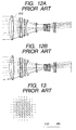
Figs. 12A and 12B show a conventional
optical system using a diffractive optical element
that utilizes diffraction light of a positive
first order. Fig. 12A shows light beam of a
positive first order (first order diffraction
light) and Fig. 12B shows light beam of a positive
second order. As shown in the figures, the light
beam of the positive second order (second order
diffraction light) defocuses greatly.
Fig. 13 shows a spot on a surface of an
image obtained by the conventional optical system
using the diffractive optical element that
utilizes diffraction light of a positive first
order. A unit of a numerical value of the optical
system which is used here is mm. As shown in the
figure, since the light beam defocuses greatly, it
forms a spot of approximately 6 mm on the surface
of the image. Although not shown in the figure,
light beam of a zero-th order defocuses in the
opposite direction of the positive second order
and forms a spot of the same size.
Originally, although a diffraction
efficiency is desirably 100% in an objective order,
the 100% diffraction efficiency cannot be realized
due to limitations of design and tolerance. Even
if a laminated DOE is used, a maximum value of the
diffraction efficiency is in the order of 98% and
the remaining 1 to 2% of light becomes additional
diffraction light.
For example, if a person 2 is photographed
against light as a subject with the sun 1 in the
background as shown in Fig. 14 using such an
optical system, flare 3 due to additional
diffraction light appears around the silhouette of
the person 2. In addition, flare due to the
additional diffraction light is also conspicuous
around a high luminance light source.
SUMMARY OF THE INVENTION
The present invention has been devised in
view of the above drawbacks, and it is an object
of the present invention to provide an optical
system in which chromatic aberration of
magnification of a high order is satisfactorily
corrected and flare caused by additional
diffraction light (unnecessary diffraction light)
is suppressed to as minimum as possible while
maintaining a high imaging performance up to
peripheral part of a field angle.
In order to attain the above-mentioned
object, an optical system of an embodiment to be
described later is characterized in that it is
provided with a diffractive optical element which
has a configuration such that a phase given to
incident light from an optical axis toward the
peripheral part in the radial direction is not
reversed in an effective area and an absolute
value of optical power on the optical axis is made
minimum.
If this diffractive optical element is
disposed ahead of an aperture stop of the optical
system (at the object side in an image-taking
system), the diffractive optical element is
preferably configured such that optical power
decreases from the optical axis toward the
peripheral part in the radial direction in the
effective area.
Conversely, if the diffractive optical
element is disposed in behind the aperture stop of
the optical system (at the image side in the
image-takig system), the diffractive optical
element is preferably configured such that optical
power increases from the optical axis toward the
peripheral part in the radial direction in the
effective area.
In the case of an optical system of a so-called
negative lead type in which optical power
becomes negative in a lens unit disposed in the
foremost part (at the object side of the image-taking
system), it is preferable to provide the
diffractive optical element in a foremost or
rearmost lens unit.
More detailed configurations of an optical
system, a diffractive optical element and an
optical apparatus will be clarified in the
following descriptions of embodiments.
BRIEF DESCRIPTION OF THE DRAWINGS
The accompanying drawings, which are
incorporated in and constitute a part of the
specification, illustrate an embodiment mode of
the invention and, together with the description,
serve to explain the principles of the invention.
DETAILED DESCRIPTION OF THE PREFERRED EMBODIMENTS
Embodiments of an optical system of the
present invention will be described with reference
to the drawings.
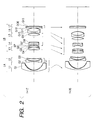
Figs. 1, 2 and 3 are sectional views of
optical systems of first to third numerical
embodiments, numerical data of which will be shown
later.
The optical system shown in Figs. 1 and 2
has a front lens part (first lens group) LA of
optical power (i.e., an inverse of a focal
distance), which is negative as a whole, and a
rear lens part (second lens group) LB of optical
power, which is positive as a whole, in order from
an object side (front) to an image side (rear).
Moreover, the front lens part LA consists of
a first unit L1 of negative optical power and a
second unit L2 of negative optical power. The
rear lens portion LB consists a third unit L3 of
positive optical power, a fourth unit L4 of
negative optical power, a fifth unit L5 of
positive optical power, a sixth unit L6 of
negative optical power and a seventh unit L7 of
substantially non-power.
Reference character SP denotes an aperture
stop for determining brightness of an optical
system and IP denotes an image surface.
Focusing from an infinite distance object to
a near distance object is carried out by moving
the second unit L2 toward the object side.
For zooming from a wide-angle end (short
focal point distance end) to a telephoto end (long
focal point distance end), the first unit L1 and
the second unit L2 of the front lens part LA
integrally move to the image side temporarily and
then move to the object side. That is, the
movement of the first unit L1 and the second unit
L2 of the front lens part LA draw a locus which is
convexed toward the image side. Any of the third
unit L3, the fourth unit L4, the fifth unit L5 and
the sixth unit L6 of the rear lens part LB moves
toward the object side while keeping the interval
between the third unit L3 and the sixth unit L6
constant. In moving, the interval between the
third unit L3 and the fourth unit L4 and the
interval between the fifth unit L5 and the sixth
unit L6 increase and the interval between the
fourth unit L4 and the fifth unit L5 decreases.
The first unit L1 consists of a negative
meniscus lens G1, a convex surface of which faces
the object side, and a surface of the meniscus
lens G1 on the image side is an aspherical surface
that is formed by a replica method.
The second unit L2 consists of a negative
lens G2 and a positive lens G3 and a surface of
the negative lens G2 on the object side is an
aspherical surface formed by the replica method.
The third unit L3 consists of a cemented
lens of a negative lens G4 and a positive lens G5,
and a positive lens G6.
The fourth unit L4 consists of a stop SP and
a cemented lens of a negative lens G7 and a
positive lens G8.
The fifth unit L5 consists of a positive
lens G9 having a convex surface on two sides and
the sixth unit L6 consists of a cemented lens of a
negative lens G10 having a concave surface on the
image side and a positive lens G11 having a convex
surface on two sides. The surface of the negative
lens G10 on the object side is aspherical.
The seventh unit L7 consists of a positive
lens G12 and a negative lens G13 and has a
diffractive optical element DOE between them.
Further, in this specification, the term
"diffractive optical element" indicates a portion
that is provided in a member and performs a
diffractive action. More specifically, it is
composed of a concentric phase grating or the like
for giving a desired phase to transmitted light.
If a height of a grating can be neglected from the
geometrically optical viewpoint, "diffractive
optical element" may be treated as a "diffractive
surface".
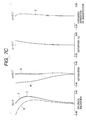
Figs. 4A and 5A show phases given by
diffractive optical elements of optical systems of
first and second embodiments. Horizontal axes
indicate a distance in the radial direction on the
basis of an optical axis and vertical axes
indicate a phase amount on the basis of a phase on
the optical axis. The phases given by the
diffractive optical elements are negative in an
effective radius and is not reversed from the
optical axis toward the peripheral part in the
radial direction. Here, "the phase is not
reversed" means that the sign of the phase does
not change from positive to negative or negative
to positive.
Figs. 4B and 5B show optical power of the
diffractive optical elements of the optical
systems of the first and the second embodiments.
Horizontal axes indicate a distance in the radial
direction on the basis of an optical axis and
vertical axes indicate optical power. The optical
power of the diffractive optical elements is zero
on the axis and increases from the optical axis
toward the peripheral part in the radial direction.
The optical system shown in Fig. 3 has a
front lens part (first lens group) LA having a
negative optical power as a whole, and a rear lens
part (second lens group) LB having a positive
optical power as a whole, in order from an object
side (front) to an image side (rear).
Moreover, the front lens part LA consists of
a first unit L1 of negative optical power and a
second unit L2 of negative optical power. The
rear lens part LB consists a third unit L3 of
positive optical power, a fourth unit L4 of
negative optical power, a fifth unit L5 of
positive optical power, and a sixth unit L6 of
negative optical power.
Reference character SP denotes an aperture
stop and IP denotes a surface of an image.
Focusing from an infinite distance object to
a near distance object is carried out by moving
the second unit L2 toward the object side.
For zooming from a wide-angle end (short
focal point distance end) to a telephoto end (long
focal point distance end), the first unit L1 and
the second unit L2 of the front lens part LA
integrally move toward the image side temporarily
and then move toward the object side. That is,
the movement of the first unit L1 and the second
unit L2 of the front lens part LA draw a locus
which is convexed toward the image guide. Any of
the third unit L3, the fourth unit L4, the fifth
unit L5 and the sixth unit L6 of the rear lens
part LB moves toward the object side while keeping
the interval between the third unit L3 and the
sixth unit L6 constant. In moving, the interval
between the third unit L3 and the fourth unit L4
and the interval between the fifth unit L5 and the
sixth unit L6 increase and the interval between
the fourth unit L4 and the fifth unit L5 decreases.
The first unit L1 consists of a negative
meniscus lens G1, a convex surface of which faces
the object side, and a diffractive optical element
DOE is provided on a surface of the meniscus lens
G1 on the object side.
The second unit L2 consists of a negative
lens G2 and a positive lens G3 and a surface of
the negative lens G2 on the object side is an
aspherical surface formed by the replica method.
The third unit L3 consists of a cemented
lens of a negative lens G4 and a positive lens G,
and a positive lens G6.
The fourth unit L4 consists of a stop SP and
a cemented lens of a negative lens G7 and a
positive lens G8.
The fifth unit L5 consists of a positive
lens G9 having a convex surface on two sides and
the sixth unit L6 consists of a cemented lens of a
negative lens G10 having a concave surface on the
image side and a positive lens G11 having a convex
surface on two sides. The surface of the negative
lens G10 on the object side is aspherical.
Fig. 6A shows phases given by diffractive
optical elements of optical systems of the third
embodiment. Horizontal axis indicates a distance
in the radial direction on the basis of an optical
axis and vertical axis indicates a phase amount on
the basis of a phase on the optical axis. The
phases given by the diffractive optical elements
are positive in an effective radius and is not
reversed from the optical axis toward the
peripheral part in the radial direction.
Fig. 6B shows optical power of the
diffractive optical elements of the optical
systems of the third embodiment. Horizontal axis
indicates a distance in the radial direction on
the basis of an optical axis and vertical axis
indicates optical power. The optical power of the
diffractive optical elements is zero on the axis
and decreases from the optical axis toward the
peripheral part in the radial direction.
As described above, the optical system of
this embodiment has at least one diffractive
optical element and a concentric or axisymmetric grating
is formed which configures a diffractive optical element in
a shape in which a phase given by the diffractive
optical element to incident light is not reversed
from an optical axis toward the peripheral part in
the radial direction and an absolute value of
optical power of the diffractive optical element
becomes minimum in the vicinity of the optical
axis. Here, a single layer grating or a plural
layer grating as disclosed in EP0895099A3 can be
applied as the grating.
Reducing optical power on an axis of a
diffractive optical element to zero or extremely
small means that light beam of an order that is
mainly used, for example, first order light beam
(first order diffraction light beam) and
additional diffraction light beam of other orders
substantially overlap to form an image. Thus,
flare due to additional diffraction light does not
appear.
In addition, since optical power of the
diffractive optical element is small, first order
diffraction light and additional diffraction light
are close to each other even in an off-axis
portion and flare due to additional diffraction
light is rarely conspicuous in the entire area of
an image.
In addition, since optical power is weak as
a whole, the number of orbicular zones of a
grating formed in a concentric shape decreases and
a diffractive optical element can be easily made
When a diffractive optical element DOE is
disposed on the object side with respect to the
stop SP as in the optical system of third
numerical embodiment, it is preferable that
optical power of the diffractive optical element
DOE decreases from an optical axis t When a
diffractive optical element DOE is toward the
peripheral part in the radial direction.
Conversely, when a diffractive optical element DOE
is disposed on the image side with respect to the
stop SP as in an optical systems of first and
second numerical embodiments, it is preferable
that optical power of the diffractive optical
element DOE increases from an optical axis toward
the peripheral part in the radial direction.
With such a configuration, it becomes
possible to satisfactorily correct chromatic
aberration of magnification of a high order in a
lens system (zoom lens) of a so-called negative
lead type in which a lens unit of negative optical
power is placed ahead of a lens unit of positive
optical power.
In addition, when a maximum value of an
absolute value of optical power of a diffractive
optical element DOE is max and a minimum value
of an absolute value of optical power of the
diffractive optical element DOE is min, it is
preferable that a condition represented by the
following expression is satisfied.
(max - min) / (max + min) > 0.5
The conditional expression (1) is a
conditional expression for limiting power on an
axis with respect to a power variation amount of
the diffraction optical element DOE which is
required for correction of chromatic aberration of
magnification of a high order. If this condition
is not satisfied, even if chromatic aberration of
magnification is satisfactorily corrected, a
defocus amount on an imaging surface of additional
diffraction light increases and flare is
conspicuous, which is not preferable.
It is preferable that a diffractive optical
element DOE is provided in a foremost unit or a
rearmost unit in the case of a zoom lens of a
negative lead type that begins with a lens unit of
negative optical power.
In order to satisfactorily correct chromatic
aberration of magnification, it becomes easy to
correct aberration if off-axis light beam is
caused to be incident on a high position from an
optical axis of a diffractive optical element.
Thus, it is preferable to dispose the diffractive
optical element in a position more distant than a
stop SP. For example, if the diffractive optical
element is disposed on the front side (object
side) with respect to the stop SP, it is
preferable to dispose it in a foremost lens unit
(lens unit disposed at the object side). On the
other hand, if the diffractive optical element is
disposed on the image side with respect to the
stop SP, it is preferable to dispose it in a
rearmost lens unit (lens unit disposed at the
image side) .
Further, when a lens unit provided with a
diffractive optical element is a last unit as in
the optical systems of the first and the second
numerical embodiments, it is preferable that this
lens unit does not move for zooming.
A diffraction efficiency of a diffractive
optical element varies depending on an angle of
incidence of light. In order to maintain the
diffraction efficiency high, it is preferable to
configure the diffractive optical element such
that the incident angle does not vary as much as
possible within a desired value range. If a
diffractive optical element is disposed in a
moving rear lens unit in a zoom lens, since the
incident angle of light on the diffractive optical
element varies greatly by zooming, it becomes
difficult to maintain the diffraction efficiency
high. Thus, it is preferable to fix a lens unit
provided with a diffractive optical element.
Consequently, it becomes possible to suppress
variation of an incident angle due to zooming to
minimum and realize a high diffraction efficiency.
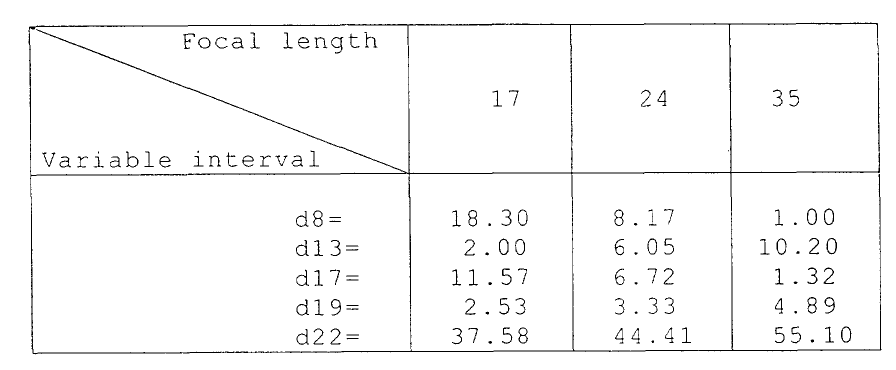
Data of the first to the third numerical
embodiments will be hereinafter shown. Reference
character ri denotes a radius of curvature on an
i-th surface counted from the object side, di
denotes an i-th interval of surfaces on the axis
in a standard state counted from the object side,
ni and νi denote an index of refraction and an
Abbe's number of an i-th member counted from the
object side for d line, respectively. Reference
character f denotes a focal length, Fno denotes an
F number and 2ω denotes an angle of view.
A shape of an aspherical surface is
represented by the following expression when it is
assumed that k, A, B, C and D are aspherical
coefficients, a traveling direction of light is
positive, a distance along an optical axis between
a crossing point of a lens surface and the optical
axis and the aspherical surface is X and a
distance between an optical axis and the
aspherical surface in a direction perpendicular
to the optical sxis is Y.
[Expression 1]
X = Y 2 / r 1+1-(1 + k)(Y / r)2 + AY 2 + BY 4 + CY 6 + DY 8
In addition, a diffraction optical element
is formed in a shape for giving a phase ψ(h,m)
represented by the following expression.
ψ(h,m) = (2π/m·λ0) (C2·h2 + C4·h4 + C6·h6 ···)
h is a height a direction perpendicular to
an optical axis; m is a diffraction order of diffractive
light; λ0 is a design wave length; and Ci is a phase coefficient (i=1, 2, 3···).
In each embodiment, the diffraction order m
of diffraction light is first order and the design
wave length λ0 is a wave length of the d line
(587.56 nm).
An embodiment of a video camera using the
optical system of the present invention as an
image-taking optical system will be described next
with reference to Fig. 10.
In Fig. 10, reference numeral 20 denotes a
video camera main body, 21 denotes an image-taking
optical system configured by the optical system of
the present invention, 22 denotes an image pick-up
element (photoelectric conversion element) such as
CCD, CMOS or the like for receiving light of a
subject image by the image-taking optical system
21, 23 denotes recording means for recording the
subject image received by the image pick-up
element 12, and 24 denotes an electronic view
finder for observing the subject image displayed
on a display element (not-shown). This display
device is composed of a liquid crystal panels or
the like, on which the subject image formed on the
image pick-up element 22 is displayed. Reference
numeral 25 denotes a liquid crystal display panel
having a function equivalent to that of the finder
24.
An optical apparatus that is compact and has
a high optical performance can be realized by
applying the optical system of the present
invention to an optical apparatus such as a video
camera as described above.
An embodiment of an original reading
apparatus such as a digital copying machine to
which the optical system of the present invention
is applied as a lens for reading an original will
be described next with reference to Fig. 11.
In the figure, reference numeral 32 denotes
an original stand glass, on a surface of which an
original 31 is placed. Reference numeral 34
denotes an illumination light source, which, for
example, consists of an Xe lamp, a halogen lamp or
the like. Reference numeral 33 denotes a
reflector that reflects light beam from the
illumination light source 34 and illuminates an
original efficiently. Reference numerals 35, 36,
37 and 38 denote first, second, third and fourth
reflecting mirrors, respectively, in this order,
which cause an optical path of the light beam from
the original 31 to be folded inside the carriage
41. Reference numeral 39 denotes a lens for
reading an original in accordance with the present
invention, which has the above-mentioned
configuration and causes the light beam based on
the image information of the original 31 to be
imaged on a surface of a reading element 40.
Reference numeral 40 denotes a line sensor (CCD)
as a reading element. Reference numeral 41
denotes a carriage that integrally accommodates
the illumination light source 34, reflector 33,
the plurality of reflecting mirrors 35, 36, 37 and
38, the lens for reading an original 39, the
reading element (line sensor) 40, and the like,
and scans the original 31 in the sub scanning
direction (in the arrow C direction in Fig. 11) by
a driving apparatus (not shown) such as a sub
scanning motor to read image information of the
original 31. Reference numeral 42 denotes a main
body. Reference numeral 43 denotes a press plate.
In this embodiment, the light beam emitted
from the illumination light source 34 illuminates
the original 31 directly or via the reflector 33.
The optical path of the light beam reflected from
the original 31 is caused to be folded inside the
carriage 41 by the first, second, third and fourth
reflecting mirrors 35, 36, 37 and 38 to form an
image of the light beam on the surface of the CCD
40 by the lens 39. Then, the image information of
the original 31 is read by causing the carriage 41
to move in the arrow C direction (sub scanning
direction) by the sub scanning motor.
In addition to this embodiment, the optical
system of the present invention is applicable to
an optical apparatus in various fields such as
optical measurement and semiconductor
manufacturing.
As described above, according to this
embodiment, an optical system, in which chromatic
aberration of magnification of a high order is
satisfactorily corrected and flare due to
additional diffraction light is suppressed as
minimum as possible while maintaining a high
imaging performance up to peripheral part of the
field angle, and an optical apparatus using the
same can be realized.
In addition, an optical system, in which on-axis
chromatic aberration and chromatic aberration
of magnification are satisfactorily corrected and
aberration is satisfactorily corrected up to
peripheral part of the field angle while securing
sufficiently long back focus, and an optical
apparatus using the same can be realized.
Morever, an optical system, in which
chromatic aberration, in particular, chromatic
aberration of magnification of a high order is
satisfactorily corrected and flare due to
additional diffraction light is not conspicuous in
spite of a wide angle of view, and an optical
apparatus using the same can be realized.
As many apparently widely different
embodiments of the present invention can be made
without departing from the spirit and scope
thereof, it is to be understood that the invention
is not limited to the specific embodiments thereof
except as defined in the appended claims.